EP0325766B1 - Récipient pour fard liquide avec applicateur - Google Patents
Récipient pour fard liquide avec applicateur Download PDFInfo
- Publication number
- EP0325766B1 EP0325766B1 EP88121162A EP88121162A EP0325766B1 EP 0325766 B1 EP0325766 B1 EP 0325766B1 EP 88121162 A EP88121162 A EP 88121162A EP 88121162 A EP88121162 A EP 88121162A EP 0325766 B1 EP0325766 B1 EP 0325766B1
- Authority
- EP
- European Patent Office
- Prior art keywords
- cap
- container body
- applicator
- barrel portion
- spiral
- Prior art date
- Legal status (The legal status is an assumption and is not a legal conclusion. Google has not performed a legal analysis and makes no representation as to the accuracy of the status listed.)
- Expired - Lifetime
Links
- 239000007788 liquid Substances 0.000 title claims description 180
- 230000007246 mechanism Effects 0.000 claims description 81
- 230000002093 peripheral effect Effects 0.000 claims description 67
- 238000007790 scraping Methods 0.000 claims description 41
- 210000000078 claw Anatomy 0.000 claims description 25
- 230000005540 biological transmission Effects 0.000 claims description 7
- 230000002265 prevention Effects 0.000 claims description 2
- 239000000057 synthetic resin Substances 0.000 description 15
- 229920003002 synthetic resin Polymers 0.000 description 15
- 230000000694 effects Effects 0.000 description 12
- 238000003756 stirring Methods 0.000 description 12
- 230000009471 action Effects 0.000 description 11
- 238000005192 partition Methods 0.000 description 10
- 239000013013 elastic material Substances 0.000 description 8
- 238000007711 solidification Methods 0.000 description 8
- 230000008023 solidification Effects 0.000 description 8
- 230000002829 reductive effect Effects 0.000 description 7
- 238000000151 deposition Methods 0.000 description 6
- 238000000605 extraction Methods 0.000 description 6
- 239000007769 metal material Substances 0.000 description 6
- 238000010276 construction Methods 0.000 description 4
- 230000008261 resistance mechanism Effects 0.000 description 4
- 230000002441 reversible effect Effects 0.000 description 4
- 238000007789 sealing Methods 0.000 description 4
- 239000000284 extract Substances 0.000 description 3
- 239000000463 material Substances 0.000 description 3
- 230000009467 reduction Effects 0.000 description 3
- 230000004323 axial length Effects 0.000 description 2
- 230000008021 deposition Effects 0.000 description 2
- 239000002184 metal Substances 0.000 description 2
- 238000000465 moulding Methods 0.000 description 2
- 239000007787 solid Substances 0.000 description 2
- 239000002131 composite material Substances 0.000 description 1
- 230000003247 decreasing effect Effects 0.000 description 1
- 230000001747 exhibiting effect Effects 0.000 description 1
- 238000004519 manufacturing process Methods 0.000 description 1
- 230000013011 mating Effects 0.000 description 1
- 238000000034 method Methods 0.000 description 1
- 230000008569 process Effects 0.000 description 1
- 239000012260 resinous material Substances 0.000 description 1
- 230000000284 resting effect Effects 0.000 description 1
- 230000000717 retained effect Effects 0.000 description 1
- 238000004804 winding Methods 0.000 description 1
Images








Classifications
-
- A—HUMAN NECESSITIES
- A45—HAND OR TRAVELLING ARTICLES
- A45D—HAIRDRESSING OR SHAVING EQUIPMENT; EQUIPMENT FOR COSMETICS OR COSMETIC TREATMENTS, e.g. FOR MANICURING OR PEDICURING
- A45D34/00—Containers or accessories specially adapted for handling liquid toiletry or cosmetic substances, e.g. perfumes
- A45D34/04—Appliances specially adapted for applying liquid, e.g. using roller or ball
- A45D34/042—Appliances specially adapted for applying liquid, e.g. using roller or ball using a brush or the like
- A45D34/045—Appliances specially adapted for applying liquid, e.g. using roller or ball using a brush or the like connected to the cap of the container
- A45D34/048—Appliances specially adapted for applying liquid, e.g. using roller or ball using a brush or the like connected to the cap of the container with stirring means
-
- B—PERFORMING OPERATIONS; TRANSPORTING
- B01—PHYSICAL OR CHEMICAL PROCESSES OR APPARATUS IN GENERAL
- B01F—MIXING, e.g. DISSOLVING, EMULSIFYING OR DISPERSING
- B01F33/00—Other mixers; Mixing plants; Combinations of mixers
- B01F33/50—Movable or transportable mixing devices or plants
- B01F33/501—Movable mixing devices, i.e. readily shifted or displaced from one place to another, e.g. portable during use
- B01F33/5011—Movable mixing devices, i.e. readily shifted or displaced from one place to another, e.g. portable during use portable during use, e.g. hand-held
Definitions
- a first subject-matter of the present invention as claimed in Claim 1 is a makeup liquid container with an applicator comprising: a container body having a barrel portion and an open neck portion; a cap designed to be screwed to said open neck portion of said container body; an applicator shaft extending downwardly from said cap into said container body; a stirrer rotatably disposed in said barrel portion, said stiffer including a member contacting the inner surface of said barrel portion of said container body and sliding along said inner surface when said stirrer is rotated; and engaging means for providing driving connection between said cap and said stirrer in such a manner that said stirrer is rotated when said cap is rotated in the screwing and/or unscrewing direction and that the driving connection between said cap and said stirrer is dismissed when said applicator shaft is extracted from said container body, characterized in that a squeezing sleeve is fitted in said open neck portion of said container body, said applicator shaft extending through said squeezing slee
- the rotary actuating means for rotationally actuating the stirrer may include engaging means which enables the stirrer to engage with the cap or the applicator shaft which is integral with the cap and inserted into the container body, such that the stirrer is rotated by the cap or the applicator shaft when the cap and, hence, the applicator shaft are rotated during screwing of the cap onto the open neck of the container body and/or unscrewing of the cap therefrom and such that the stirrer is disengaged from the cap or the applicator shaft automatically when the applicator shaft is extracted from the container body.
- the rotary actuating means also may be of the type which is capable of rotating the stirrer by means of a rotary actuator exposed on the bottom of the container body.
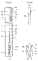
- the rotatable member 2 splined to the cap 4 is rotatingly actuated so that the spiral member 9 of the rotatable member 2 rotates so as to scrape off any makeup liquid from the inner surface of the barrel portion of the container body 1.
- the user screws the cap 4 again onto the open neck portion 6 of the container body.
- the rotatable member 2 rotates also in this case so that the spiral member 9 performs scraping action in the reverse direction.
- the rotation of the spiral member 9, which performs the scraping function also causes a stirring action to stir the makeup liquid in the container body thereby preventing undesirable solidification of the makeup liquid.
- the parts described hereinabove without limitation of material, e.g., the rotatable cylinder and the spiral members 9,9, cap 4, applicator shaft 5,and the bottom member 15, may be formed by molding from a synthetic resin.
- the applicator 10 is typically a brush having bristles of a synthetic resin or animal hair.
- the applicator shaft 5 and the stirrer 91 are splined to each other so that they are relatively movable in the axial direction but not in the rotational direction. Since the cap 4 rotates during unscrewing, the applicator shaft 5 is rotated during removal of the cap, with the result that the stirrer 91 also rotates to stir the makeup liquid in the container body 1, thereby preventing the solidification and deposition of the makeup liquid. At the same time, by positioning the stirrer in the close proximity of the inner surface of the container body 1, the solid content of the makeup liquid depositing to the wall surface of the container body 1 is scraped and dissolved again in the liquid. Since the lower portion of the container body 1 is restricted to such an extent as to just receive the applicator 10, it is possible to minimize the makeup liquid which remains in the container body without being used.
- the squeezing sleeve 3 is made of a soft elastic material such as a rubber or a soft synthetic resin.
- the squeezing sleeve 3 is provided with an outwardly extending flange 21 which is adapted to reset on the top of the open neck portion 6.
- the lower end of the squeezing sleeve 3 is so restricted as to make a resilient pressure contact with the applicator shaft 5. In this state, the squeezing sleeve 3 is fitted and fixed by friction in the open neck portion 6.
- the applicator shaft 5 has a cylindrical upper portion 95 of a large diameter which fits in the upper half portion of the cap 4 and is fixed thereto by mutual engagement between the engaging ridges 76 and 79.
- the portion of the applicator shaft 5 immediately under the large-diameter cylindrical portion 95 corresponding to the squeezing sleeve 3 has a cylindrical form with a reduced diameter and the lower portion of this reduced-diameter cylindrical portion is shaped as a rod.
- An applicator 10 such as a brush is secured to the lower end of the rod.
- Wedge-shaped engaging tabs 96 are provided the outer surface of the upper end of the rod,for engagement with the scraping blades 93.
- Components other that those specifically mentioned as being made from a metal can be molded from a synthetic resin.
- Figs. 11 and 12 show a sixth embodiment of the present invention.
- the saw-teeth-like ratchet teeth 32b and the engaging claws 32a of the fifth embodiment are replaced with each other.
- the teeth 32b are formed on the inner peripheral surface of the ring 31, while the engaging claws 32a are formed to suspend from the lower end of the rotatable cylinder 7.
- the sixth embodiment operates in the same manner as that of the fifth embodiment.
- the bottom member 15 provides a restricted bottom of the container body 1 so as to minimize the quantity of the makeup liquid which remains in the container body 1 without being used.
- a reference numeral 17 denotes a seal ring, while a numeral 31 denotes a ring which is integrally connected to the upper ends of the spiral strings 9a, 9a.
- the cap 4 is a substantially cylindrical member having a partition plate 23 formed at an intermediate portion thereof such as to have a substantially H-shaped cross-section, and is internally threaded at its lower portion so as to engage with the external thread of the open neck portion.
- An outer member 24 made of a decorative metallic member is fitted around the cylindrical body of the cap 4.
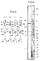
- Fig. 15(a) The arrangement for attaining engagement between the applicator shaft 5 and the rotatable cylinder 7 shown in Fig. 15(a) is only illustrative. Any construction which enables the rotatable cylinder 5 to rotate as a unit with the applicator shaft 5 while allowing the latter to move vertically relative to the rotatable cylinder 7 may be used in place of the arrangement of Fig. 15(a). For instance, arrangements as shown in Figs. 15(b), 15(c) and 15(d) can be used equally well.
- the arrangement shown in Fig. 15(b) employs a ridge 46 which engages with an engaging notch 48 of the type shown in Fig. 15(a).
- the scraping is effected without fail each time the cap 4 is removed, so that the scraping operation is facilitated and is conducted without being forgotten.
- the solidified content of the makeup liquid scraped off the inner surface of the container body 1 is dissolved again in the makeup liquid in the bottom of the container, thus preventing any decrease of the effective amount of the makeup liquid and undesirable thinning of the same.
- a reference numeral 54 denotes a sealing "O" ring which is received in a groove formed in the outer peripheral surface of a flange 53 which extends outward from the bottom member 15.
- the "O" ring makes a frictional contact with the inner surface of the barrel portion 8 so as to provide an optimum friction between the barrel portion 8 and the spiral member 9, thus serving as a rotation resistance means for preventing unintentional rotation of the spiral member 9 due to a drag in the ratchet mechanism 32.
- the ratchet mechanism 32 does not transmit torque when the cap 4 is rotated in the screwing direction.
- the spiral member 9 is kept stationary without rotating even when a slight force is transmited through the ratchet mechanism due to dragging, thanks to the effect of the "O" ring 54 which serves as the rotation resistance mechanism.
- the rotation of the applicator shaft 5 is transmitted from the rotatable cylinder 7 to the spiral member 9 through the ratchet mechanism 32 against the resistance caused by the rotation resistance mechanism 51, whereby the spiral member 9 scrapes makeup liquid off the inner surface of the barrel portion 8 of the container body 1.
- the applicator shaft 5 integral with the cap 4 rotates to cause a rotation of the rotatable cylinder 7 splined to the applicator shaft 5.
- the rotation of the rotatable cylinder 7 is transmitted through the ratchet mechanism 32 to the spiral member 9 so as to effect scraping of makeup iquid component off the inner surface of the barrel portion 8 of the container body 1, whereby the scraped makeup liquid component is dissolved again in the makeup liquid in the makeup liquid container thereby preventing reduction in the effective amount of the makeup liquid and undesirable thinning of the same.
- the rotation of the spiral member 9 effectively stirs the makeup liquid in the container body so as to prevent solidification of the makeup liquid in the container body.
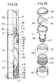
- the spiral member 9 has a cup-shaped bottom member 15 provided at its upper end with an outward flange 81,and a pair of spiral strings 9a,9a protruding upright from diametrically opposing portions of the flange 81 such as to make contact with the inner surface of the barrel portion 8, with a ring member 41 connected to the upper ends of the spiral strings 9a,9a.
- the spiral member 9 is rotatably disposed in the barrel portion 8 of the container body 1 with its flange 81 held in a substantially close contact with the barrel portion 8.
- the spiral strings 9a, 9a are so shaped that they can scrape solidified makeup liquid component off the inner surface of the barrel portion 8 towards the bottom of the container body 1 when the cap 4 is rotated in the unscrewing direction.
- a polygonal or square hole 7a formed in the bottom wall of the rotatable cylinder 7 fits around the portion of the applicator shaft 5 having a polygonal or square shape so that the applicator shaft 5 is allowed to move up and down relative to the rotatable cylinder 7 but is prevented from rotating relative thereto.
- the rotatable cylinder 7 fits in the ring member 41 with its flange 85 resting on the top surface of the ring member 41 so as not to move downward, therefrom.
- the ratchet mechanism 32 is capable of transmitting torque only when the cap 4 is rotated in the unscrewing direction and does not transmit torque when the cap 4 is rotated in the screwing direction. Therefore, when the cap 4 is rotated in the screwing direction, the spiral member 9 is kept stationary due to resistance provided by the ratchet mechanism 70 or the makeup liquid itself, though the rotatable cylinder 7 rotates in the same direction as the cap 4. Conversely, when the cap 4 is rotated in the unscrewing direction, the rotation of the applicator shaft 5 is transmitted to the spiral member 9 through the rotatable cylinder 7, whereby the spiral member 9 performs scraping action to scrape any component of makeup liquid off the inner surface of the barrel portion 8 of the container body 1. In this state, the lower ratchet 70 is maintained in a freed state so as not to impede the rotation of the spiral member 9.
- the squeezing sleeve 3 is made of a soft elastic material such as a rubber or a soft synthetic resin and is provided at the upper end thereof with an outward flange 21 which is adapted to rest on the top of the open neck portion 6.
- the squeezing sleeve 3 also is provided on the outer peripheral surface thereof with an engaging ridge 3a for engagement with the engaging ridge 11a on the open neck portion 6.
- the lower end of the squeezing sleeve 3 forms a restricted opening the wall of which makes resilient contact with the applicator shaft 5.
- the bottom cap 112 is a deep-saucer-shaped member having a double peripheral wall,and is provided on the upper part of the inner surface of the peripheral wall 117 with an engaging ridge 118 which engages with the aforementioned engaging ridge 116.
- the bottom cap 112 is further provided at its lower portion with a plurality of vertical grooves formed in the inner peripheral surface thereof for engagement with the vertical ridges 117.
- the bottom cap 112 is fixedly fitted on the lower outer surface of the rotatable bottom member 111.
Landscapes
- Chemical & Material Sciences (AREA)
- Chemical Kinetics & Catalysis (AREA)
- Closures For Containers (AREA)
- Containers And Packaging Bodies Having A Special Means To Remove Contents (AREA)
Claims (15)
- Récipient pour liquide de maquillage avec applicateur comprenant:
un corps de récipient (1) ayant une partie de réservoir (8) et une partie à goulot ouvert (6);
un capuchon (4) conçu pour être vissé à ladite partie à goulot ouvert (6) dudit corps de récipient (1);
une tige d'applicateur (5) descendant depuis ledit capuchon (4) jusque dans ledit corps de récipient (1);
un agitateur (9; 91) placé en rotation dans ladite partie de réservoir (8), ledit agitateur (9; 91) comportant un élément (9) entrant en contact avec la surface interne de ladite partie de réservoir (8) dudit corps de récipient (1) et glissant le long de ladite paroi interne lorsque ledit agitateur (9; 91) est mis en rotation;
et des moyens d'engagement pour fournir une liaison d'entraînement entre ledit capuchon (4) et ledit agitateur (9; 91) de sorte que ledit agitateur (9; 91) soit mis en rotation lorsque ledit capuchon (4) est mis en rotation dans le sens de vissage et/ou de dévissage et que la liaison d'entraînement entre ledit capuchon (4) et ledit agitateur (9; 91) soit rompue lorsque ladite tige d'applicateur (5) est extraite dudit corps de récipient (1),
caractérisé en ce qu'une gaine d'essorage (3) est ajustée dans ladite partie à goulot ouvert (6) dudit corps de récipient (1), ladite tige d'applicateur (5) passant à travers ladite gaine d'essorage (3);
et en ce que ledit élément (9) dudit agitateur (9; 91) est un élément à spirale (9) entrant en contact avec ladite surface interne de ladite partie de réservoir (8) dudit corps de récipient (1) en forme de spirale. - Récipient pour liquide de maquillage avec applicateur selon la revendication 1, dans lequel ledit moyen d'engagement comporte un cylindre tournant (7) à l'extrémité inférieure duquel est relié ledit élément à spirale (9), ledit cylindre tournant (7) étant ajusté en rotation dans ladite partie à goulot ouvert (6) de sorte de dépasser vers le haut au-dessus de ladite partie à goulot ouvert (6), ladite gaine d'essorage (3) étant ajustée dans ledit cylindre tournant (7), la partie dudit cylindre tournant (7) dépassant au-dessus de ladite partie à goulot ouvert (6) étant emboîtée par cannelure audit capuchon (4) de sorte que ledit cylindre tournant (7) et ledit élément à spirale (9) soient mis en rotation lorsque le capuchon (4) est mis en rotation dans l'un et l'autre sens.
- Récipient pour liquide de maquillage avec applicateur selon la revendication 1, dans lequel ledit moyen d'engagement comporte un cylindre tournant (7) dont la surface externe est constituée par ledit élément à spirale (9), ledit cylindre tournant (7) étant admis en rotation dans ladite partie de réservoir (8) dudit corps de récipient (1), ledit moyen d'engagement comportant en outre une première nervure d'engagement verticale prévue sur la surface externe de ladite tige d'applicateur (5) au niveau d'une partie inférieure de celle-ci et une deuxième nervure d'engagement formée sur la surface interne dudit cylindre tournant (7) au niveau d'une partie inférieure de celui-ci et susceptible de s'engager avec ladite première nervure d'engagement lorsque ledit capuchon (4) est mis en rotation dans le sens de vissage et/ou de dévissage.
- Récipient pour liquide de maquillage avec applicateur selon l'une quelconque des revendications 1 à 3, dans lequel ledit agitateur (9) possède une pluralité de lames tordues (93), et dans lequel ledit moyen d'engagement comporte des moyens d'engagement à cannelure entre ladite tige d'applicateur (5) et ledit agitateur (9) susceptibles de transmettre la rotation de ladite tige d'applicateur (5) audit agitateur (9) lorsque ledit capuchon (4) est mis en rotation dans le sens de dévissage.
- Récipient pour liquide de maquillage avec applicateur selon l'une quelconque des revendications 1 à 4, comprenant en outre un mécanisme à cliquet (32) prévu sur le trajet de transmission de la rotation dudit capuchon (4) et dudit élément à spirale (9) par l'intermédiaire de la tige d'applicateur (5).
- Récipient pour liquide de maquillage selon la revendication 5, dans lequel ledit élément à spirale (9) est muni d'une bague (31) à son extrémité supérieure, et dans lequel ledit moyen d'engagement comporte un cylindre tournant (7) ajusté en rotation dans ladite partie à goulot ouvert (6) de sorte de dépasser vers le haut de celle-ci, ledit cylindre tournant (7) étant emboîté par cannelure sur ledit capuchon (4), ledit mécanisme à cliquet (32) étant prévu entre l'extrémité inférieure dudit cylindre tournant (7) et ladite bague (31) de sorte que la rotation dudit capuchon (4) ne soit transmise audit élément à spirale (9) par l'intermédiaire dudit cylindre tournant (7) et dudit mécanisme à cliquet (32) que lorsque ledit capuchon (4) est mis en rotation dans le sens du dévissage.
- Récipient pour liquide de maquillage avec applicateur selon la revendication 5, dans lequel ledit élément à spirale (9) est pourvu d'une bague (41) à son extrémité inférieure, et dans lequel ledit moyen d'engagement comporte un cylindre tournant (7) emboîté par cannelure à la surface extérieure de ladite tige d'applicateur (5), ledit mécanisme à cliquet (32) étant prévu entre ledit cylindre tournant (7) et ladite bague (41) de sorte que la rotation dudit capuchon (4) ne soit transmise audit élément à spirale (9) par l'intermédiaire de ladite tige d'applicateur (5), dudit cylindre tournant (7) et dudit mécanisme à cliquet (32) que lorsque ledit capuchon (4) est mis en rotation dans le sens de dévissage.
- Récipient pour maquillage avec applicateur selon la revendication 5, dans lequel ledit élément à spirale (9) est pourvu à son extrémité supérieure d'un élément de bague (41) et est placé dans la partie de réservoir (8) dudit corps de récipient(1) de sorte que sa rotation par rapport à ladite partie de réservoir (8), lorsque ledit capuchon (4) est mis en rotation dans le sens du vissage, est empêchée par un mécanisme de blocage de rotation qui est obtenu par le frottement entre ledit élément à spirale (9) et la surface interne de ladite partie de réservoir (8) ou par un autre mécanisme à cliquet (51) agissant entre ledit élément à spirale (9) et ladite surface interne de ladite partie de réservoir (8), et dans lequel ledit moyen d'engagement comprend un cylindre tournant (7) emboîté par cannelure à la surface externe de ladite tige d'applicateur (5) et coopérant avec ledit élément de bague (41) dudit élément à spirale (9) en formant ledit mécanisme à cliquet (32) de sorte que la rotation de ladite tige d'applicateur (5) ne soit transmise audit élément à spirale (9) que lorsque le capuchon (4) est mis en rotation dans le sens de dévissage.
- Récipient pour liquide de maquillage avec applicateur selon la revendication 5, dans lequel ledit élément à spirale (9) est pourvu à son extrémité supérieure d'un élément de bague (41) ayant des dents de scie périphériques internes (32a) et également d'un élément de fond (15) en forme de coupelle prévu sur son extrémité inférieure, et est placé dans ladite partie de réservoir (8) dudit corps de récipient (1) de sorte que sa rotation par rapport à ladite partie de réservoir (8) soit empêchée lorsque le capuchon (4) est mis en rotation dans le sens de vissage, et dans lequel ledit moyen d'engagement comprend un cylindre tournant (7) emboîté par cannelure à la surface externe de ladite tige d'applicateur (5) et ayant des ergots (32b) s'engageant avec lesdites dents de scie (32a) sur ledit élément de bague (41) de façon à former ledit mécanisme à cliquet (32) de sorte que la rotation de ladite tige d'applicateur (5) ne soit transmise audit élément à spirale (9) que lorsque ledit capuchon (4) est mis en rotation dans le sens de dévissage.
- Récipient pour liquide de maquillage avec applicateur selon l'une quelconque des revendications 5 à 9, comprenant en outre un deuxième mécanisme à cliquet (70) prévu entre ledit corps de récipient (1) et ledit cylindre tournant (7) ou ledit élément à spirale (9) et susceptible de transmettre la force motrice dans la direction opposée à la direction de transmission de force dans le premier mécanisme à cliquet (32).
- Récipient pour liquide de maquillage avec applicateur comprenant:
un corps de récipient (1) ayant une partie de réservoir (8) et une partie à goulot ouvert (6);
un capuchon (4) susceptible d'être vissé à la partie externe de la dite partie à goulot ouvert (6);
une tige d'applicateur (5) descendant depuis ledit capuchon (4) jusque dans ladite partie de réservoir (8);
un agitateur (9; 91) placé en rotation dans ladite partie de réservoir (8) dudit corps de récipient (1); et
des moyens d'actionnement rotatifs pour actionner en rotation ledit agitateur (9; 91) et présenté depuis le bas de ladite partie de réservoir (8) dudit corps de récipient (1),
caractérisé en ce qu'une gaine d'essorage (3) est ajustée dans la partie à goulot ouvert (6) dudit corps de récipient (1), ladite tige d'applicateur (5) passant à travers ladite gaine d'essorage (3);
et en ce que ledit agitateur (9; 91) comprend un élément à spirale (9) se mettant en contact avec la surface interne de ladite partie de réservoir (8) dudit corps de récipient (1) en forme de spirale et glissant le long de ladite surface interne lorsque l'agitateur (9; 91) est mis en rotation. - Récipient pour liquide de maquillage avec applicateur selon la revendication 11, dans lequel ledit agitateur (9; 91) est fixé à un élément de fond tournant (111) qui est reçu de manière tournante et étanche au liquide dans ladite partie de réservoir (8), et ledit moyen d'actionnement rotatif comprend un capuchon de fond (112) ajusté en rotation dans l'ouverture d'extrémité inférieure de ladite partie de réservoir (8), et s'engageant avec ledit élément de fond tournant (111).
- Récipient pour liquide de maquillage avec applicateur selon la revendication 11 ou 12, dans lequel ladite partie de réservoir (8) possède une bague de maintien (110) s'ajustant dans l'ouverture d'extrémité inférieure de ladite partie de réservoir (8) et ayant une surface conique concave, et dans lequel ledit moyen d'actionnement rotatif comprend un élément de fond tournant (111) ajusté de manière tournante et étanche au liquide dans l'ouverture d'extrémité inférieure de ladite partie de réservoir (8) par l'intermédiaire de ladite bague de maintien (110), ledit agitateur (9; 91) comprenant une lame de raclage en spirale dépassant à l'aplomb de la surface supérieure dudit élément de fond tournant (111) et reçue dans ladite partie de réservoir (8) en contact glissant avec la surface interne de ladite partie de réservoir (8).
- Récipient pour liquide de maquillage avec applicateur selon la revendication 12 ou 13, comprenant en outre un mécanisme à cliquet (32) prévu entre ledit capuchon de fond (112) et ladite partie de réservoir (8).
- Récipient pour liquide de maquillage avec applicateur selon la revendication 13, comprenant en outre un mécanisme à cliquet (32) prévu entre un capuchon de fond (112) fixé audit élément de fond tournant (111) et susceptible de permettre audit capuchon de fond (112) de ne tourner que dans un sens positif par rapport à ladite partie de réservoir (8), dans lequel ledit agitateur (9; 91) ayant un élément à spirale (9) réalisant un contact glissant avec la surface interne de ladite partie de réservoir (8) et ayant une forme en spirale telle que ledit élément à spirale (9) racle les substances déposées sur la surface interne de ladite partie de réservoir (8) vers le bas lorsque ledit capuchon (112) est mis en rotation dans le sens positif.
Applications Claiming Priority (10)
| Application Number | Priority Date | Filing Date | Title |
|---|---|---|---|
| JP1072188U JPH0611Y2 (ja) | 1988-01-29 | 1988-01-29 | 化粧具付き化粧液容器 |
| JP1072288U JPH0612Y2 (ja) | 1988-01-29 | 1988-01-29 | 化粧具付き化粧液容器 |
| JP10722/88U | 1988-01-29 | ||
| JP10721/88U | 1988-01-29 | ||
| JP12410/88U | 1988-02-01 | ||
| JP1241088U JPH0613Y2 (ja) | 1988-02-01 | 1988-02-01 | 化粧具付き化粧液容器 |
| JP13376/88U | 1988-02-03 | ||
| JP1337688U JPH0614Y2 (ja) | 1988-02-03 | 1988-02-03 | 化粧具付き化粧液溶器 |
| JP11520688U JPH0726968Y2 (ja) | 1988-09-01 | 1988-09-01 | 化粧具付き化粧液容器 |
| JP115206/88U | 1988-09-01 |
Publications (3)
| Publication Number | Publication Date |
|---|---|
| EP0325766A2 EP0325766A2 (fr) | 1989-08-02 |
| EP0325766A3 EP0325766A3 (en) | 1990-05-09 |
| EP0325766B1 true EP0325766B1 (fr) | 1995-07-05 |
Family
ID=27519208
Family Applications (1)
| Application Number | Title | Priority Date | Filing Date |
|---|---|---|---|
| EP88121162A Expired - Lifetime EP0325766B1 (fr) | 1988-01-29 | 1988-12-16 | Récipient pour fard liquide avec applicateur |
Country Status (5)
| Country | Link |
|---|---|
| US (2) | US4984918A (fr) |
| EP (1) | EP0325766B1 (fr) |
| AU (1) | AU616924B2 (fr) |
| CA (1) | CA1331966C (fr) |
| DE (1) | DE3854118T2 (fr) |
Cited By (1)
| Publication number | Priority date | Publication date | Assignee | Title |
|---|---|---|---|---|
| CN106793863A (zh) * | 2014-10-20 | 2017-05-31 | 香奈儿香水美妆品公司 | 包括具有颈部的容器的美容用品 |
Families Citing this family (24)
| Publication number | Priority date | Publication date | Assignee | Title |
|---|---|---|---|---|
| US5027838A (en) * | 1990-05-14 | 1991-07-02 | Chesebrough-Pond's Usa Co., Division Of Conopco, Inc. | Cosmetic applicator brush |
| FR2663823B1 (fr) * | 1990-06-27 | 1994-02-11 | Oreal | Ensemble applicateur pour produit cosmetique pateux. |
| US5172992A (en) * | 1992-03-09 | 1992-12-22 | Risdon Corporation | Mascara container with stirrer |
| FR2713510B1 (fr) * | 1993-12-10 | 1996-01-26 | Oreal | Dispositif pour préparer à l'abri de l'air, une pâte à usage cosmétique. |
| USD373219S (en) | 1995-05-16 | 1996-08-27 | Cosmair, Inc. | Eyeliner container |
| FR2771907B1 (fr) | 1997-12-10 | 2000-02-18 | Oreal | Ensemble de conditionnement et d'application d'un produit, notamment cosmetique |
| JP2002112832A (ja) * | 2000-08-03 | 2002-04-16 | Tokyo Parts Kk | 液体用容器 |
| DE20217821U1 (de) * | 2002-11-18 | 2003-03-20 | Schwan-Stabilo Cosmetics GmbH & Co., 90562 Heroldsberg | Schminkgerät |
| KR100734946B1 (ko) * | 2002-11-18 | 2007-07-06 | 슈반-스타빌로 코스메틱스 게엠베하 운트 콤파니 카게 | 도포 장치, 특히 메이크업 장치 |
| US6964336B2 (en) * | 2003-06-03 | 2005-11-15 | Valley Design Inc. | Child resistant container for applicator |
| FR2868669B1 (fr) * | 2004-04-09 | 2007-07-20 | Oreal | Dispositif de conditionnement et d'application d'un produit. |
| FR2884500A1 (fr) * | 2005-04-18 | 2006-10-20 | Oreal | Dispositif de conditionnement et d'application. |
| DE102005037633B4 (de) * | 2005-08-09 | 2009-11-19 | Schwan-Stabilo Cosmetics Gmbh & Co. Kg | Kosmetikbehälter mit integriertem Mischereinsatz |
| DE202005012516U1 (de) * | 2005-08-09 | 2006-12-21 | Schwan-Stabilo Cosmetics Gmbh & Co. Kg | Kosmetikbehälter mit integriertem Mischereinsatz |
| DE202007010060U1 (de) * | 2007-07-17 | 2007-10-18 | H & M Gutberlet Gmbh | Applikatoreinrichtung zum Auftragen eines flüssigen Mediums |
| US20130101334A1 (en) | 2011-10-24 | 2013-04-25 | Avon Products, Inc. | Functional Dynamic Cosmetic Package |
| US8517621B2 (en) * | 2011-10-24 | 2013-08-27 | Avon Products, Inc. | Cosmetic cap sealing system |
| US8864398B2 (en) | 2011-11-07 | 2014-10-21 | Avon Products Inc. | Press-on cosmetic applicator system |
| US8967896B2 (en) | 2011-11-23 | 2015-03-03 | Dean Johnson | Cosmetic apparatus and method |
| KR101400178B1 (ko) * | 2014-01-28 | 2014-05-28 | 변영찬 | 내벽 스크래퍼가 구비된 화장품용기 |
| US10039363B2 (en) | 2016-05-02 | 2018-08-07 | L'oreal | Multi-phase cosmetic composition mixing pack |
| US12239205B2 (en) | 2020-09-30 | 2025-03-04 | L'oreal | Systems, devices, and methods including a mixing element for temporarily mixing immiscible components of a multi-phase composition |
| KR102869170B1 (ko) * | 2022-11-18 | 2025-10-13 | 코스맥스 주식회사 | 묻어나지 않는 립글로스 화장품 |
| WO2025038567A1 (fr) * | 2023-08-14 | 2025-02-20 | Coty Inc. | Emballage pour formulation cosmétique |
Family Cites Families (15)
| Publication number | Priority date | Publication date | Assignee | Title |
|---|---|---|---|---|
| US1944067A (en) * | 1932-11-04 | 1934-01-16 | Claude R Collins | Fountain toothbrush |
| US2631826A (en) * | 1950-08-24 | 1953-03-17 | Wallace P Wolf | Sediment stirrer |
| DE1073166B (de) * | 1957-06-18 | 1960-01-14 | Düsseldorf-Heerdt Karl Heinz Ohrt | Nagellackflasche |
| US2904808A (en) * | 1958-11-24 | 1959-09-22 | Massman Irwin | Nail polish container, mixer and applicator |
| US2990834A (en) * | 1959-07-06 | 1961-07-04 | Nicholas C Amen | Mascara container and applicator |
| US3085281A (en) * | 1961-06-07 | 1963-04-16 | Massman Irwin | Nail polish container, mixer and removable applicator |
| FR1318657A (fr) * | 1961-12-20 | 1963-02-22 | équipement avec agitateur pour flacons de vernis et produits volatils analogues | |
| BE638867A (fr) * | 1962-11-28 | |||
| US3311941A (en) * | 1965-02-08 | 1967-04-04 | Revlon | Containers for fingernail enamel |
| US3336624A (en) * | 1965-02-19 | 1967-08-22 | Revlon | Container having applicator and rotatable stirrer |
| US3456923A (en) * | 1968-02-12 | 1969-07-22 | Ruth M Zeuzem | Container with cap-operated stirring mechanism |
| GB1393823A (en) * | 1973-04-27 | 1975-05-14 | Aubry F A J | Device for stirring and dispensing products comprising separable elements |
| GB1543461A (en) * | 1976-08-18 | 1979-04-04 | Ciba Geigy Ag | Multichamber pack |
| EP0013721B1 (fr) * | 1979-01-30 | 1981-12-16 | Kurt Vogelsang GmbH | Dispositif de mélange pour récipients cylindriques remplis de peinture ou de laque |
| DE3032409A1 (de) * | 1980-08-28 | 1982-04-15 | Klaus-Peter 3052 Bad Nenndorf Dahm | Behaelter fuer fluessige substanzen mit zugehoerigem auftragelement |
-
1988
- 1988-12-13 US US07/283,843 patent/US4984918A/en not_active Expired - Lifetime
- 1988-12-14 AU AU26872/88A patent/AU616924B2/en not_active Ceased
- 1988-12-16 EP EP88121162A patent/EP0325766B1/fr not_active Expired - Lifetime
- 1988-12-16 DE DE3854118T patent/DE3854118T2/de not_active Expired - Fee Related
- 1988-12-16 CA CA000586154A patent/CA1331966C/fr not_active Expired - Fee Related
-
1990
- 1990-10-30 US US07/605,487 patent/US5074693A/en not_active Expired - Fee Related
Cited By (2)
| Publication number | Priority date | Publication date | Assignee | Title |
|---|---|---|---|---|
| CN106793863A (zh) * | 2014-10-20 | 2017-05-31 | 香奈儿香水美妆品公司 | 包括具有颈部的容器的美容用品 |
| CN106793863B (zh) * | 2014-10-20 | 2020-11-06 | 香奈儿香水美妆品公司 | 包括具有颈部的容器的美容用品 |
Also Published As
| Publication number | Publication date |
|---|---|
| AU616924B2 (en) | 1991-11-14 |
| US4984918A (en) | 1991-01-15 |
| EP0325766A3 (en) | 1990-05-09 |
| US5074693A (en) | 1991-12-24 |
| EP0325766A2 (fr) | 1989-08-02 |
| DE3854118D1 (de) | 1995-08-10 |
| AU2687288A (en) | 1989-08-03 |
| CA1331966C (fr) | 1994-09-13 |
| DE3854118T2 (de) | 1996-03-28 |
Similar Documents
| Publication | Publication Date | Title |
|---|---|---|
| EP0325766B1 (fr) | Récipient pour fard liquide avec applicateur | |
| EP1503647B1 (fr) | Recipient ameliore pour contenir un produit | |
| JP3020122B2 (ja) | ペースト状の化粧品用の塗布器アセンブリ | |
| US2983946A (en) | Paint container assembly | |
| US3095598A (en) | Dispensing container | |
| EP0350535B1 (fr) | Récipient avec applicateur pour liquide de maquillage | |
| CA2079844C (fr) | Contenant a mascara | |
| NZ285392A (en) | Container for adhesive; comprises inner and outer tubes, the inner tube having a screw-threaded spindle rotatably fixed to it | |
| JP2002112832A (ja) | 液体用容器 | |
| KR100902274B1 (ko) | 스틱 형상 화장품용 용기 | |
| EP0598223A2 (fr) | Capsule de distributeur pour conteneur de substance fluide avec bec de distribution mobile | |
| EP0332593A2 (fr) | Récipient distributeur pour fluide visqueux ou produit en forme de bâton solidifié, en particulier pour cosmétiques | |
| CA1338666C (fr) | Contenant pour liquide d'appoint, avec applicateur | |
| WO1997035499A1 (fr) | Distributeur de produits a applicateur a brosse | |
| US6186689B1 (en) | Cosmetic container having a clean corkage insert | |
| JPH061066Y2 (ja) | 化粧具付き化粧液容器 | |
| JPH068Y2 (ja) | 化粧具付き化粧液容器 | |
| JP2551942Y2 (ja) | 液状収納物の塗布容器 | |
| JPH061051Y2 (ja) | マスカラ容器 | |
| JPH0744249Y2 (ja) | 液状収納物の塗布容器 | |
| JPS6317383Y2 (fr) | ||
| JPH0310887Y2 (fr) | ||
| JP7733617B2 (ja) | 塗布具付きキャップ及び塗布容器 | |
| EP1204357B1 (fr) | Distributeur de matieres coulantes tendres | |
| EP0659366A1 (fr) | Distributeur de produit avec douille de rétention d'un élément d'essorage |
Legal Events
| Date | Code | Title | Description |
|---|---|---|---|
| PUAI | Public reference made under article 153(3) epc to a published international application that has entered the european phase |
Free format text: ORIGINAL CODE: 0009012 |
|
| AK | Designated contracting states |
Kind code of ref document: A2 Designated state(s): CH DE FR GB IT LI NL |
|
| PUAL | Search report despatched |
Free format text: ORIGINAL CODE: 0009013 |
|
| AK | Designated contracting states |
Kind code of ref document: A3 Designated state(s): CH DE FR GB IT LI NL |
|
| 17P | Request for examination filed |
Effective date: 19901016 |
|
| 17Q | First examination report despatched |
Effective date: 19920821 |
|
| GRAA | (expected) grant |
Free format text: ORIGINAL CODE: 0009210 |
|
| AK | Designated contracting states |
Kind code of ref document: B1 Designated state(s): CH DE FR GB IT LI NL |
|
| REF | Corresponds to: |
Ref document number: 3854118 Country of ref document: DE Date of ref document: 19950810 |
|
| ET | Fr: translation filed | ||
| ITF | It: translation for a ep patent filed | ||
| PLBE | No opposition filed within time limit |
Free format text: ORIGINAL CODE: 0009261 |
|
| STAA | Information on the status of an ep patent application or granted ep patent |
Free format text: STATUS: NO OPPOSITION FILED WITHIN TIME LIMIT |
|
| 26N | No opposition filed | ||
| PGFP | Annual fee paid to national office [announced via postgrant information from national office to epo] |
Ref country code: CH Payment date: 20001215 Year of fee payment: 13 |
|
| PGFP | Annual fee paid to national office [announced via postgrant information from national office to epo] |
Ref country code: NL Payment date: 20001231 Year of fee payment: 13 |
|
| PG25 | Lapsed in a contracting state [announced via postgrant information from national office to epo] |
Ref country code: LI Free format text: LAPSE BECAUSE OF NON-PAYMENT OF DUE FEES Effective date: 20011231 Ref country code: CH Free format text: LAPSE BECAUSE OF NON-PAYMENT OF DUE FEES Effective date: 20011231 |
|
| REG | Reference to a national code |
Ref country code: GB Ref legal event code: IF02 |
|
| PG25 | Lapsed in a contracting state [announced via postgrant information from national office to epo] |
Ref country code: NL Free format text: LAPSE BECAUSE OF NON-PAYMENT OF DUE FEES Effective date: 20020701 |
|
| REG | Reference to a national code |
Ref country code: CH Ref legal event code: PL |
|
| NLV4 | Nl: lapsed or anulled due to non-payment of the annual fee |
Effective date: 20020701 |
|
| PGFP | Annual fee paid to national office [announced via postgrant information from national office to epo] |
Ref country code: FR Payment date: 20021210 Year of fee payment: 15 |
|
| PGFP | Annual fee paid to national office [announced via postgrant information from national office to epo] |
Ref country code: GB Payment date: 20021211 Year of fee payment: 15 |
|
| PGFP | Annual fee paid to national office [announced via postgrant information from national office to epo] |
Ref country code: DE Payment date: 20021219 Year of fee payment: 15 |
|
| PG25 | Lapsed in a contracting state [announced via postgrant information from national office to epo] |
Ref country code: GB Free format text: LAPSE BECAUSE OF NON-PAYMENT OF DUE FEES Effective date: 20031216 |
|
| PG25 | Lapsed in a contracting state [announced via postgrant information from national office to epo] |
Ref country code: DE Free format text: LAPSE BECAUSE OF NON-PAYMENT OF DUE FEES Effective date: 20040701 |
|
| GBPC | Gb: european patent ceased through non-payment of renewal fee |
Effective date: 20031216 |
|
| PG25 | Lapsed in a contracting state [announced via postgrant information from national office to epo] |
Ref country code: FR Free format text: LAPSE BECAUSE OF NON-PAYMENT OF DUE FEES Effective date: 20040831 |
|
| REG | Reference to a national code |
Ref country code: FR Ref legal event code: ST |
|
| PG25 | Lapsed in a contracting state [announced via postgrant information from national office to epo] |
Ref country code: IT Free format text: LAPSE BECAUSE OF NON-PAYMENT OF DUE FEES;WARNING: LAPSES OF ITALIAN PATENTS WITH EFFECTIVE DATE BEFORE 2007 MAY HAVE OCCURRED AT ANY TIME BEFORE 2007. THE CORRECT EFFECTIVE DATE MAY BE DIFFERENT FROM THE ONE RECORDED. Effective date: 20051216 |