EP0325767A2 - Disjoncteur de puissance à basse tension avec des contacts interchangeables - Google Patents
Disjoncteur de puissance à basse tension avec des contacts interchangeables Download PDFInfo
- Publication number
- EP0325767A2 EP0325767A2 EP88121213A EP88121213A EP0325767A2 EP 0325767 A2 EP0325767 A2 EP 0325767A2 EP 88121213 A EP88121213 A EP 88121213A EP 88121213 A EP88121213 A EP 88121213A EP 0325767 A2 EP0325767 A2 EP 0325767A2
- Authority
- EP
- European Patent Office
- Prior art keywords
- contact
- arm
- low
- circuit breaker
- voltage circuit
- Prior art date
- Legal status (The legal status is an assumption and is not a legal conclusion. Google has not performed a legal analysis and makes no representation as to the accuracy of the status listed.)
- Granted
Links
Images


Classifications
-
- H—ELECTRICITY
- H01—ELECTRIC ELEMENTS
- H01H—ELECTRIC SWITCHES; RELAYS; SELECTORS; EMERGENCY PROTECTIVE DEVICES
- H01H9/00—Details of switching devices, not covered by groups H01H1/00 - H01H7/00
- H01H9/30—Means for extinguishing or preventing arc between current-carrying parts
- H01H9/38—Auxiliary contacts on to which the arc is transferred from the main contacts
- H01H9/383—Arcing contact pivots relative to the movable contact assembly
-
- H—ELECTRICITY
- H01—ELECTRIC ELEMENTS
- H01H—ELECTRIC SWITCHES; RELAYS; SELECTORS; EMERGENCY PROTECTIVE DEVICES
- H01H1/00—Contacts
- H01H1/58—Electric connections to or between contacts; Terminals
- H01H1/5822—Flexible connections between movable contact and terminal
-
- H—ELECTRICITY
- H01—ELECTRIC ELEMENTS
- H01H—ELECTRIC SWITCHES; RELAYS; SELECTORS; EMERGENCY PROTECTIVE DEVICES
- H01H1/00—Contacts
- H01H2001/001—Contacts providing easy replacement of contacts
Definitions
- the invention relates to low-voltage circuit breakers with interchangeable contacts according to the preamble of claim 1.
- the invention has for its object to provide low-voltage circuit breakers with on-site replaceable main contacts and flex bands.
- the invention relates to the exchange of the main contacts of the movable contact arm.
- the fixed main contacts can be easily released according to the known prior art.
- the invention offers the advantage that the articulated arm can be designed in such a way that when the contact system closes, the auxiliary contacts lead and lag when opened. Furthermore, the part of the contact arm carrying the main and auxiliary contacts can advantageously be designed such that electrodynamically acting forces increase the contact pressure and that lamellar main contacts can be accommodated.
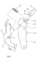
- Fig. 1 shows a contact system of a low-voltage circuit breaker with a movable contact arm, which is designed as a two-part articulated arm with a contact carrier part 1, a main arm 2 and a releasable joint 3, 4, 13 connecting the contact carrier part 1 and the main arm 2
- Contact carrier part 1 a main and an auxiliary contact 5, 6 are attached, to which corresponding stationary contacts 11, 12 are assigned on the fixed part 8 of the contact system.
- the movable contact arm is pivotally attached with its main arm 2 via a bearing pin 7 to the fixed part of the contact system and the electrical connection between the fixed lower connecting lug and the contact carrier part 1 is made with a flexible band 9.
- the releasable joint 3, 4, 13 between the contact carrier part 1 and main arm 2 consists of a hinge pin 3, which is fixed to the contact carrier part 1, a slot hole 4 open on one side in the main arm 2 and a pin holder 13, which is designed as a U-shaped leaf spring and, when the joint is assembled, the hinge pin 3 in the slot hole open on one side 4 holds and is easily removable.
- An insulating cap 14 made of elastic material secures the seat of the pin holder 13 on the hinge pin 3 and influences the course of the arc in the switch. With a contact pressure spring 10, the required contact pressure on the main contacts 5, 11 is generated when the contact system is closed (see also FIG. 5).
- the contact pressure spring 10 is held on the contact carrier part 1 and on the main arm 2 by spring receptacles 21, 22, respectively.
- the effect of the contact pressure spring 10 is limited by a stop 23 which is located on the main arm 2.
- the contact carrier part 1 shows an extension 24 below the main contact 5 with which the current flow is influenced in such a way that the electrodynamically acting forces increase the contact pressure on the main contacts 5, 11.
- the contact carrier part 1 and the main arm 5 are U-shaped in cross section. In the OPEN position of the contact system, with the arc quenching chamber removed, the flexible band 9 can be detached from the fixed part of the contact system 8 via the flexible band fastening 15, which is easily accessible from above, and can be removed together with the contact carrier part 1 from the contact system.
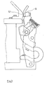
- Fig. 2 shows the disassembled movable contact arm with the contact arm support 1, the main arm 2 of the contact pressure spring 10, the pin holder 13 a flattened stop pin 16.
- the contact support part 1 carries the fixed hinge pin 3, which is held in the slot hole 4 open on one side.
- the pin holder 13, which is designed as a U-shaped leaf spring, lies after its placement with its back 17 on the flattened stop pin 16 of the recesses 20 in the main arm 2 relative to the one-sided one Slot holder 4 is stored.
- bearing hole 4 sheet 13 - the side legs 18 of the U-shaped leaf spring can be bent slightly apart and thus release the hinge pin 3.
- the movable main contact 5 initially rolls on the fixed contact 11 until the auxiliary contacts 6 and 12 touch each other.
- the main contacts 5, 11 only open after the auxiliary contacts 6, 12 have touched.
- the movable auxiliary contact 6 then lifts off the fixed auxiliary contact 12.
Landscapes
- Physics & Mathematics (AREA)
- Electromagnetism (AREA)
- Breakers (AREA)
- Arc-Extinguishing Devices That Are Switches (AREA)
Applications Claiming Priority (2)
| Application Number | Priority Date | Filing Date | Title |
|---|---|---|---|
| DE3802183A DE3802183A1 (de) | 1988-01-26 | 1988-01-26 | Niederspannungs-leistungsschalter mit auswechselbaren kontakten |
| DE3802183 | 1988-01-26 |
Publications (3)
| Publication Number | Publication Date |
|---|---|
| EP0325767A2 true EP0325767A2 (fr) | 1989-08-02 |
| EP0325767A3 EP0325767A3 (en) | 1990-10-17 |
| EP0325767B1 EP0325767B1 (fr) | 1994-04-27 |
Family
ID=6345986
Family Applications (1)
| Application Number | Title | Priority Date | Filing Date |
|---|---|---|---|
| EP88121213A Expired - Lifetime EP0325767B1 (fr) | 1988-01-26 | 1988-12-19 | Disjoncteur de puissance à basse tension avec des contacts interchangeables |
Country Status (2)
| Country | Link |
|---|---|
| EP (1) | EP0325767B1 (fr) |
| DE (2) | DE3802183A1 (fr) |
Cited By (3)
| Publication number | Priority date | Publication date | Assignee | Title |
|---|---|---|---|---|
| GB2260027A (en) * | 1991-09-30 | 1993-03-31 | Long & Crawford Limited | Electrical switchgear |
| WO2001067477A1 (fr) * | 2000-03-09 | 2001-09-13 | Siemens Aktiengesellschaft | Pole de commutation pour appareils de commutation basse tension comportant un support de contacts a mouvement lineaire |
| US6689979B1 (en) | 1999-07-02 | 2004-02-10 | Siemens Aktiengesellschaft | Switching contact arrangement of a low voltage circuit breaker with main contacts, intermediate contact and arcing contacts |
Families Citing this family (4)
| Publication number | Priority date | Publication date | Assignee | Title |
|---|---|---|---|---|
| DE19635366A1 (de) | 1996-08-21 | 1998-02-26 | Siemens Ag | Bewegbare Kontaktanordnung für einen Niederspannungs-Leistungsschalter mit einem Schwenklager |
| DE19727696B4 (de) * | 1997-06-20 | 2007-09-13 | Siemens Ag | Bewegbarer Schaltkontakt für Niederspannungs-Leistungsschalter |
| DE19957259C2 (de) * | 1999-11-19 | 2001-11-29 | Siemens Ag | Schaltkontaktanordnung mit einer feststehenden Baugruppe aus Vorkontakt und Lichtbogenhorn |
| DE102009007475A1 (de) | 2009-01-30 | 2010-08-05 | Siemens Aktiengesellschaft | Schaltmechanismus für ein Schaltgerät mit einem bei einem verschweißten Kontaktglied und bei einer Öffnungsbetätigung in einer Zwischenschaltstellung verbleibenden Schalthebel |
Family Cites Families (9)
| Publication number | Priority date | Publication date | Assignee | Title |
|---|---|---|---|---|
| CH116447A (de) * | 1925-09-16 | 1926-09-01 | Oerlikon Maschf | Doppelkontaktvorrichtung für elektrische Schaltapparate. |
| US2025697A (en) * | 1933-04-22 | 1935-12-24 | Westinghouse Electric & Mfg Co | Circuit interrupter |
| US2209038A (en) * | 1938-06-06 | 1940-07-23 | Clark Controller Co | Electric contact |
| GB648081A (en) * | 1948-11-18 | 1950-12-28 | Donovan Electrical Company Ltd | Improvements connected with electric switches |
| DE966808C (de) * | 1950-08-04 | 1957-09-12 | Voigt & Haeffner Ag | Bewegtes Schaltstueck mit Lichtbogenleitblech fuer Selbstschalter, Schuetze od. dgl. |
| US3004125A (en) * | 1959-06-18 | 1961-10-10 | Licentia Gmbh | Switch |
| US3134878A (en) * | 1962-07-19 | 1964-05-26 | Gen Electric | Movable contact arm assembly |
| DE3432086A1 (de) * | 1984-08-28 | 1986-03-06 | Siemens AG, 1000 Berlin und 8000 München | Kontaktanordnung mit einer die kontaktkraft vergroessernden stromabhaengigen kraft |
| EP0225207B1 (fr) * | 1985-10-31 | 1991-05-15 | Merlin Gerin | Chaîne cinématique de transmission entre le mécanisme de commande et les pôles d'un disjoncteur électrique à boîtier isolant moulé |
-
1988
- 1988-01-26 DE DE3802183A patent/DE3802183A1/de active Granted
- 1988-12-19 EP EP88121213A patent/EP0325767B1/fr not_active Expired - Lifetime
- 1988-12-19 DE DE3889318T patent/DE3889318D1/de not_active Expired - Fee Related
Cited By (4)
| Publication number | Priority date | Publication date | Assignee | Title |
|---|---|---|---|---|
| GB2260027A (en) * | 1991-09-30 | 1993-03-31 | Long & Crawford Limited | Electrical switchgear |
| US6689979B1 (en) | 1999-07-02 | 2004-02-10 | Siemens Aktiengesellschaft | Switching contact arrangement of a low voltage circuit breaker with main contacts, intermediate contact and arcing contacts |
| WO2001067477A1 (fr) * | 2000-03-09 | 2001-09-13 | Siemens Aktiengesellschaft | Pole de commutation pour appareils de commutation basse tension comportant un support de contacts a mouvement lineaire |
| US6803844B2 (en) | 2000-03-09 | 2004-10-12 | Siemens Aktiengesellschaft | Switchgear for low-voltage switching units with a linearly displaceable contact support |
Also Published As
| Publication number | Publication date |
|---|---|
| DE3802183A1 (de) | 1989-08-03 |
| DE3802183C2 (fr) | 1991-05-23 |
| EP0325767A3 (en) | 1990-10-17 |
| EP0325767B1 (fr) | 1994-04-27 |
| DE3889318D1 (de) | 1994-06-01 |
Similar Documents
| Publication | Publication Date | Title |
|---|---|---|
| DE3411275C2 (fr) | ||
| EP0680065B1 (fr) | Disjoncteur de protection de surcharge | |
| DE3411273C2 (de) | Leistungsschalter | |
| DE3411276A1 (de) | Leistungsschalter | |
| DE3339401C2 (fr) | ||
| EP0325767A2 (fr) | Disjoncteur de puissance à basse tension avec des contacts interchangeables | |
| EP1880453B1 (fr) | Élément de connexion et de base pour recevoir un limiteur de surtension enfichable | |
| DE4026425C1 (fr) | ||
| DE3789738T2 (de) | Ausschalter. | |
| EP0727091A1 (fr) | Dispositif de protection contre les surtensions | |
| EP0131297B1 (fr) | Appareil de commutation électromagnétique | |
| DE2541650B2 (de) | Miniaturrelais | |
| DE19526591A1 (de) | Elektrischer Schalter | |
| DE102005028474B4 (de) | Kontaktsystem, insbesondere für ein Schaltgerät | |
| WO1997027605A1 (fr) | Dispositif de commutation electrique | |
| DE1438953A1 (de) | Selbsttaetiger Schutzschalter | |
| EP0081805A2 (fr) | Agencement de contact pour un interrupteur automatique | |
| DE4013272A1 (de) | Elektrisches schaltgeraet | |
| EP0862784B1 (fr) | Disjoncteur de surintensite | |
| EP0632928B1 (fr) | Interrupteur a vide avec un montage en boucle de courant | |
| DE19529869C2 (de) | Elektrisches selbstöffnende Kontakte aufweisendes Kontaktsystem | |
| EP0375087B1 (fr) | Dispositif de contact avec pivot conducteur pour un levier de contact | |
| DE3219368A1 (de) | Elektrischer leistungsschalter mit elektromagnetisch wirkendem ausloesemechanismus | |
| DE462544C (de) | Elektrischer Schalter mit federnd gegeneinandergedrueckten Stromschlussstuecken | |
| DE3513803A1 (de) | Elektrischer schalter |
Legal Events
| Date | Code | Title | Description |
|---|---|---|---|
| PUAI | Public reference made under article 153(3) epc to a published international application that has entered the european phase |
Free format text: ORIGINAL CODE: 0009012 |
|
| AK | Designated contracting states |
Kind code of ref document: A2 Designated state(s): DE FR GB IT |
|
| PUAL | Search report despatched |
Free format text: ORIGINAL CODE: 0009013 |
|
| AK | Designated contracting states |
Kind code of ref document: A3 Designated state(s): DE FR GB IT |
|
| 17P | Request for examination filed |
Effective date: 19910416 |
|
| 17Q | First examination report despatched |
Effective date: 19930326 |
|
| GRAA | (expected) grant |
Free format text: ORIGINAL CODE: 0009210 |
|
| AK | Designated contracting states |
Kind code of ref document: B1 Designated state(s): DE FR GB IT |
|
| REF | Corresponds to: |
Ref document number: 3889318 Country of ref document: DE Date of ref document: 19940601 |
|
| ITF | It: translation for a ep patent filed | ||
| ET | Fr: translation filed | ||
| GBT | Gb: translation of ep patent filed (gb section 77(6)(a)/1977) |
Effective date: 19940715 |
|
| PLBE | No opposition filed within time limit |
Free format text: ORIGINAL CODE: 0009261 |
|
| STAA | Information on the status of an ep patent application or granted ep patent |
Free format text: STATUS: NO OPPOSITION FILED WITHIN TIME LIMIT |
|
| 26N | No opposition filed | ||
| REG | Reference to a national code |
Ref country code: GB Ref legal event code: 732E |
|
| REG | Reference to a national code |
Ref country code: FR Ref legal event code: TP |
|
| REG | Reference to a national code |
Ref country code: GB Ref legal event code: IF02 |
|
| PGFP | Annual fee paid to national office [announced via postgrant information from national office to epo] |
Ref country code: GB Payment date: 20050112 Year of fee payment: 17 |
|
| PGFP | Annual fee paid to national office [announced via postgrant information from national office to epo] |
Ref country code: FR Payment date: 20050118 Year of fee payment: 17 |
|
| PGFP | Annual fee paid to national office [announced via postgrant information from national office to epo] |
Ref country code: DE Payment date: 20050131 Year of fee payment: 17 |
|
| PG25 | Lapsed in a contracting state [announced via postgrant information from national office to epo] |
Ref country code: IT Free format text: LAPSE BECAUSE OF NON-PAYMENT OF DUE FEES;WARNING: LAPSES OF ITALIAN PATENTS WITH EFFECTIVE DATE BEFORE 2007 MAY HAVE OCCURRED AT ANY TIME BEFORE 2007. THE CORRECT EFFECTIVE DATE MAY BE DIFFERENT FROM THE ONE RECORDED. Effective date: 20051219 Ref country code: GB Free format text: LAPSE BECAUSE OF NON-PAYMENT OF DUE FEES Effective date: 20051219 |
|
| PG25 | Lapsed in a contracting state [announced via postgrant information from national office to epo] |
Ref country code: DE Free format text: LAPSE BECAUSE OF NON-PAYMENT OF DUE FEES Effective date: 20060701 |
|
| GBPC | Gb: european patent ceased through non-payment of renewal fee |
Effective date: 20051219 |
|
| PG25 | Lapsed in a contracting state [announced via postgrant information from national office to epo] |
Ref country code: FR Free format text: LAPSE BECAUSE OF NON-PAYMENT OF DUE FEES Effective date: 20060831 |
|
| REG | Reference to a national code |
Ref country code: FR Ref legal event code: ST Effective date: 20060831 |