EP0325775A1 - Strömungsgünstige Schutzvorrichtung für eine Informationseinrichtung für Unterseeboote - Google Patents
Strömungsgünstige Schutzvorrichtung für eine Informationseinrichtung für Unterseeboote Download PDFInfo
- Publication number
- EP0325775A1 EP0325775A1 EP88121474A EP88121474A EP0325775A1 EP 0325775 A1 EP0325775 A1 EP 0325775A1 EP 88121474 A EP88121474 A EP 88121474A EP 88121474 A EP88121474 A EP 88121474A EP 0325775 A1 EP0325775 A1 EP 0325775A1
- Authority
- EP
- European Patent Office
- Prior art keywords
- protective tube
- submarine
- pipe
- information equipment
- telescopic
- Prior art date
- Legal status (The legal status is an assumption and is not a legal conclusion. Google has not performed a legal analysis and makes no representation as to the accuracy of the status listed.)
- Granted
Links
- 230000001681 protective effect Effects 0.000 claims abstract description 26
- XLYOFNOQVPJJNP-UHFFFAOYSA-N water Substances O XLYOFNOQVPJJNP-UHFFFAOYSA-N 0.000 claims abstract description 13
- 230000000694 effects Effects 0.000 description 1
- 238000000034 method Methods 0.000 description 1
Images

Classifications
-
- B—PERFORMING OPERATIONS; TRANSPORTING
- B63—SHIPS OR OTHER WATERBORNE VESSELS; RELATED EQUIPMENT
- B63G—OFFENSIVE OR DEFENSIVE ARRANGEMENTS ON VESSELS; MINE-LAYING; MINE-SWEEPING; SUBMARINES; AIRCRAFT CARRIERS
- B63G8/00—Underwater vessels, e.g. submarines; Equipment specially adapted therefor
- B63G8/38—Arrangement of visual or electronic watch equipment, e.g. of periscopes, of radar
Definitions
- the invention relates to a streamlined protective device for at least one vertically movable information device for submarines, consisting of a vertically movable pipe device for the carrier of the information device extending inside.
- a generally known protective device of the above type for, for example, the periscope device consists of a hydraulically vertically displaceable pipe device of greater length, which is guided vertically on columns mounted in a fixed manner in the tower structure of the submarine and whose lower section is immersed in the hull of the submarine when the periscope device is retracted, so that its upper section, which is aerodynamically designed and exposed to the water flow in the operating state, is in the non-operating position in the tower structure.
- Through the pipe device extends the rod-shaped device carrier of the periscope device, to the upper end of which the rotatable periscope head protruding from the pipe device is fastened.
- a disadvantage of this known protective device is that the submarine can be located more easily because, when the periscope device is extended, the upper end region of the protective pipe device also projects from the water, which has relatively large side surfaces due to its aerodynamic design, which makes the reflective surface for the enemy Radar is magnified. This applies to all speeds of the submarine.
- the object of the invention is to provide a protective device of the type mentioned in the introduction, in which the detectability of the submarine is reduced at low speed.
- the solution to the problem is based on the protective device mentioned in the introduction and is characterized in that the tube device is provided with an additional, outer, streamlined protective tube surrounding it, which is exposed to the water flow in the extended state of the information device, and in that the additional protective tube is telescopic.
- the detectability of the submarine with the information device extended at a low driving speed is significantly reduced because the additional and telescopically designed protective tube is not telescopic, so that it is only exposed to the water flow to the extent that it is in the collapsed state from the tower structure of the Submarine sticks out. It has been shown that, at low driving speeds, it is not necessary for the length section of the pipe device protecting the information device, which is exposed to the water flow, to be of streamlined design, because then no significant swirling of the water surface occurs.
- the upper section of the pipe device, which immediately surrounds the device holder for the information device can be circular and as small in diameter as the diameter of the device holder just allows.
- the end area of the pipe device which protrudes from the water and is now small in diameter, offers the opposing radar only a minimal reflection surface, which is difficult to detect. Furthermore, because of the minimal area of the protruding end region of the pipe device, the effects of the sea impact on e.g. B. optronic devices so that their function is safer. Furthermore, the advantages of the known pipe device are also present in the protective device according to the invention, in that the aerodynamic, telescopic protective tube is telescoped for this purpose in order to minimize the flow resistance in the water and the turbulence of the water surface when the submarine has a relatively fast cruising speed.
- the telescopic part of the protective tube according to the invention is easy to mount and operate.
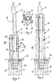
- FIGS. 1 to 4 show the exemplary embodiment essentially in a side view with some upper parts in a sectional view, the exemplary embodiment also in FIG different heights is shown. The parts shown in the section are drawn rotated by 90 ° for a better representation of the other parts.
- FIG. 5 shows a top view of the exemplary embodiment with the periscope device omitted, the above-mentioned upper parts being drawn here in the correct position.
- the protective device shown consists, on the one hand, of a pipe device 1, which is composed of an upper pipe section 2 and of a lower pipe section 3, and, on the other hand, of a telescopic protective pipe 4, which surrounds the upper pipe section 2.
- the tube device 1 carries in its interior a known periscope device 5, which is composed of an elongated support element 6, which extends through the tube device, and the periscope head 7, which protrudes from the top of the tube device.
- the periscope device is connected to the tube device 1 in the usual way axially stationary, but rotatably.
- FIGS. 1, 2 and 4 show the tube device 1 and thus the periscope device 5 in the fully extended position, in which the upper section 2 of the device 1 completely protrudes from the tower structure 12 of the submarine.
- FIG. 3 shows the fully retracted position of devices 1, 4 and 5.
- the telescopic protective tube 4 provided in the upper section 2 of the pipe device 1 and surrounding the upper section consists of two telescopic sections 15 and 16, the lower section 15 being stationary in relation to the pipe device 1.
- a hydraulic cylinder 18 engages the upper section 16 via a cross member 17, which in turn engages the pipe device 1 with its other end, so that the upper section 16 can be extended and retracted when the cylinder 18 is acted upon.
- the upper telescopic section 16 of the additional protective tube 4 is guided on the pipe device 1, specifically by means of a pipe section 19, which in turn is fastened to the telescopic section 16 by means of the central part 17 and further transverse parts 20 and 21.
- the pipe section 19 surrounds the upper pipe section 2 of the pipe device 1 essentially coaxially.
- Figures 1 and 3 show the additional protective tube 4 in the fully retracted state, while the protective tube in Figures 2 and 4 is shown in the fully extended state.
- the procedure can be such that a further information device is accommodated in the upper telescopic section 16, e.g. an antenna device.
- a mast device can also be used, at the top of which other information devices, e.g. Optronic devices, and / or one or more antenna devices are provided.
Landscapes
- Engineering & Computer Science (AREA)
- Radar, Positioning & Navigation (AREA)
- Mechanical Engineering (AREA)
- Aviation & Aerospace Engineering (AREA)
- Laying Of Electric Cables Or Lines Outside (AREA)
- Instruments For Viewing The Inside Of Hollow Bodies (AREA)
- Radar Systems Or Details Thereof (AREA)
Abstract
Description
- Die Erfindung betrifft eine strömungsgünstige Schutzvorrichtung für wenigstens eine vertikal verfahrbare Informationseinrichtung für Unterseeboote, bestehend aus einer vertikal verfahrbaren Rohreinrichtung für den sich in ihrem Innern erstreckenden Träger der Informationseinrichtung.
- Eine allgemein praktisch bekannte Schutzvorrichtung der vorstehenden Art für beispielsweise die Periskopeinrichtung besteht aus einer hydraulisch vertikal verfahrbaren Rohreinrichtung größerer Länge, die an im Turmaufbau des Unterseebootes ortsfest gelagerten Säulen vertikal geführt ist und deren unterer Abschnitt beim Einziehen der Periskopeinrichtung in den Rumpf des Unterseebootes eintaucht, so daß sich deren oberer Abschnitt, der strömungsgünstig ausgebildet und im Betriebszustand der Wasserströmung ausgesetzt ist, in Nichtbetriebsstellung im Turmaufbau befindet. Durch die Rohreinrichtung erstreckt sich der stangenförmige Geräteträger der Periskopeinrichtung,an dessen Oberende der aus der Rohreinrichtung herausragende, drehbare Periskopkopf befestigt ist.
- Nachteilig bei dieser bekannten Schutzvorrichtung ist, daß das Unterseeboot leichter geortet werden kann, weil bei ausgefahrener Periskopeinrichtung außer dem Periskopkopf auch der obere Endbereich der schützenden Rohreinrichtung aus dem Wasser herausragt, der wegen seiner strömungsgünstigen Ausbildung relativ große Seitenflächen aufweist, wodurch die Reflexionsfläche für das gegnerische Radar vergrößert ist. Dies gilt für alle Fahrgeschwindigkeiten des Unterseebootes.
- Die Aufgabe der Erfindung besteht in der Schaffung einer Schutzvorrichtung der einleitend angeführten Art, bei der die Detektierbarkeit des Unterseebootes bei geringer Fahrgeschwindigkeit verringert ist.
- Die Lösung der Aufgabe geht von der einleitend angeführten Schutzvorrichtung aus und kennzeichnet sich dadurch, daß die Rohreinrichtung mit einem zusätzlichen, äußeren, sie oben umgebenden, strömungsgünstigen Schutzrohr versehen ist, das im ausgefahrenen Zustand der Informationseinrichtung der Wasserströmung ausgesetzt ist, und daß das zusätzliche Schutzrohr teleskopisch ausgebildet ist.
- Mit dieser Lösung ist die Detektierbarkeit des Unterseebootes mit ausgefahrener Informationseinrichtung bei niedriger Fahrgeschwindigkeit wesentlich verringert, weil das zusätzliche und teleskopisch ausgebildete Schutzrohr nicht teleskopiert ist, so daß es nur insoweit der Wasserströmung ausgesetzt ist, als es im zusammengefahrenen Zustand aus dem Turmaufbau des Unterseebootes herausragt. Es hat sich gezeigt, daß es bei niedrigen Fahrgeschwindigkeiten nicht erforderlich ist, daß der der Wasserströmung ausgesetzte Längenabschnitt der die Informationseinrichtung schützenden Rohreinrichtung stromlinienförmig ausgebildet ist, weil dann keine nennenswerte Verwirbelung der Wasseroberfläche eintritt. Der obere Abschnitt der Rohreinrichtung, die den Geräteträger für das Informationsgerät unmittelbar umgibt, kann daher kreisrund und im Durchmesser so klein sein, wie es der Durchmesser des Geräteträgers gerade noch zuläßt. Dadurch bietet der aus dem Wasser herausragende, im Durchmesser nunmehr kleine Endbereich der Rohreinrichtung dem gegnerischen Radar nur eine minimale Reflexionsfläche, die schwer zu detektieren ist. Ferner sind wegen der minimalen Fläche des herausragenden Endbereichs der Rohreinrichtung auch die Auswirkungen des Seeschlages auf z. B. Optronikgeräte geringer, so daß deren Funktion sicherer ist. Ferner sind bei der erfindungsgemäßen Schutzvorrichtung auch die Vorteile der bekannten Rohreinrichtung vorhanden, indem das strömungsgünstige, teleskopische Schutzrohr zu diesem Zweck teleskopiert wird, um den Strömungswiderstand im Wasser und die Verwirbelung der Wasseroberfläche zu minimieren, wenn das Unterseeboot eine relativ schnelle Fahrgeschwindigkeit hat.
- Gemäß den Ausgestaltungen nach den Unteransprüchen ergibt sich eine einfache Lagerung und Hubbetätigung des teleskopierbaren Teils des erfindungsgemäßen Schutzrohres.
- Die Erfindung ist nachstehend anhand eines in den anliegenden Zeichnungen dargestellten Ausführungsbeispieles näher erläutert. Die Figuren 1 bis 4 zeigen das Ausführungsbeispiel im wesentlichen in Seitenansicht mit einigen oberen Teilen in Schnittdarstellung, wobei das Ausführungsbeispiel ferner in verschiedenen Höhenstellungen dargestellt ist. Die im Schnitt gezeigten Teile sind zur besseren Darstellung der übrigen Teile um 90° verdreht gezeichnet. Figur 5 zeigt eine Aufsicht auf das Ausführungsbeispiel mit weggelassener Periskopeinrichtung, wobei die genannten oberen Teile hier in der richtigen Lage gezeichnet sind.
- Gemäß den Figuren 1 und 2 besteht die gezeigte Schutzvorrichtung zum einen aus einer Rohreinrichtung 1, die sich aus einem oberen Rohrabschnitt 2 und aus einem unteren Rohrabschnitt 3 zusammensetzt, und zum anderen aus einem teleskopischen Schutzrohr 4, das den oberen Rohrabschnitt 2 umgibt. Die Rohreinrichtung 1 trägt in ihrem Innern eine bekannte Periskopeinrichtung 5, die sich aus einem länglichen Trägerelement 6, das sich durch die Rohreinrichtung hindurcherstreckt, und aus dem Periskopkopf 7 zusammensetzt, der oben aus der Rohreinrichtung herausragt. Die Periskopeinrichtung ist mit der Rohreinrichtung 1 in üblicher Weise axial ortsfest, jedoch drehbar verbunden. An der Rohreinrichtung 1 greifen ferner mittels einer Traverse 8 zwei hydraulische Zylinder 9 und 10 an, wobei an der Traverse ebenfalls auch die Rohreinrichtung 1 befestigt ist, wie es in den Figuren 3 und 4 angedeutet ist, wobei die Zylinder und die Rohreinrichtung den Rumpf 11 des Unterseebootes mit ihrem Unterende abgedichtet durchdringen und sich sonst im wesentlichen in dem mit 12 angedeuteten Turmaufbau des Unterseebootes befinden. Ferner befinden sich im Turmaufbau 12 des Unterseebootes zwei übliche Führungssäulen 13 und 14, die zwischen sich die Rohreinrichtung 1 aufnehmen, wie es aus den Figuren 1 bis 4 hervorgeht, so daß die Rohreinrichtung und damit auch die Periskopeinrichtung sicher vertikal verfahren werden können, und zwar durch die Beaufschlagung der beiden hydraulischen Zylinder 9 und 10. Die Figuren 1, 2 und 4 zeigen die Rohreinrichtung 1 und damit die Periskopeinrichtung 5 in voll ausgefahrener Stellung, in welcher der obere Abschnitt 2 der Einrichtung 1 vollständig aus dem Turmaufbau 12 des Unterseebootes herausragt. Figur 3 zeigt dagegen die voll eingefahrene Stellung der Einrichtungen 1, 4 und 5.
- Gemäß den Figuren 1 bis 4 besteht das im oberen Abschnitt 2 der Rohreinrichtung 1 vorgesehene und den oberen Abschnitt umgebende, teleskopische Schutzrohr 4 aus zwei Teleskopabschnitten 15 und 16, wobei der untere Abschnitt 15 in Bezug auf die Rohreinrichtung 1 ortsfest ausgebildet ist. An dem oberen Abschnitt 16 greift über ein Querteil 17 ein Hydraulikzylinder 18 an, der seinerseits mit seinem anderen Ende an der Rohreinrichtung 1 angreift, so daß der obere Abschnitt 16 bei Beaufschlagung des Zylinders 18 ausgefahren und eingefahren werden kann.
- Der obere Teleskopabschnitt 16 des zusätzlichen Schutzrohres 4 ist an der Rohreinrichtung 1 geführt, und zwar mittels eines Rohrstückes 19, das wiederum mittels des Mittelteiles 17 und weiterer Querteile 20 und 21 am Teleskopabschnitt 16 befestigt ist. Das Rohrstück 19 umgibt den oberen Rohrabschnitt 2 der Rohreinrichtung 1 im wesentlichen koaxial. Die Figuren 1 und 3 zeigen das zusätzliche Schutzrohr 4 in vollständig eingefahrenem Zustand, während das Schutzrohr in den Figuren 2 und 4 in vollständig ausgefahrenem Zustand gezeigt ist.
- Aus Figur 5 ist zu erkennen, daß das zusätzliche Schutzrohr 4 strömungsgünstig ausgebildet ist,das in seinem ausgefahrenen Zustand, und zwar auch dann, wenn es nicht teleskopiert ist, der Wasserströmung ausgesetzt ist. Es sind daher beide Tele skoparme 15 und 16 des Schutzrohres 4 strömungsgünstig ausgebildet.
- In Ergänzung kann so vorgegangen werden, daß in dem oberen Teleskopabschnitt 16 ein weiteres Informationsgerät untergebracht ist, z.B. eine Antenneneinrichtung. Weiterhin ist es möglich, daß anstelle der Periskopeinrichtung 5 in der Rohreinrichtung 1 auch eine Masteinrichtung verwendet werden kann, an deren Oberende andere Informationsgeräte, z.B. Optronikgeräte, und/oder eine oder mehrere Antenneneinrichtungen vorgesehen sind.
Claims (3)
Applications Claiming Priority (2)
| Application Number | Priority Date | Filing Date | Title |
|---|---|---|---|
| DE3801941A DE3801941A1 (de) | 1988-01-23 | 1988-01-23 | Stroemungsguenstige schutzvorrichtung fuer eine informationseinrichtung fuer unterseeboote |
| DE3801941 | 1988-01-23 |
Publications (2)
| Publication Number | Publication Date |
|---|---|
| EP0325775A1 true EP0325775A1 (de) | 1989-08-02 |
| EP0325775B1 EP0325775B1 (de) | 1991-08-14 |
Family
ID=6345856
Family Applications (1)
| Application Number | Title | Priority Date | Filing Date |
|---|---|---|---|
| EP88121474A Expired - Lifetime EP0325775B1 (de) | 1988-01-23 | 1988-12-22 | Strömungsgünstige Schutzvorrichtung für eine Informationseinrichtung für Unterseeboote |
Country Status (2)
| Country | Link |
|---|---|
| EP (1) | EP0325775B1 (de) |
| DE (2) | DE3801941A1 (de) |
Cited By (2)
| Publication number | Priority date | Publication date | Assignee | Title |
|---|---|---|---|---|
| EP1462360A1 (de) * | 2003-02-27 | 2004-09-29 | Gabler Maschinenbau GmbH | Schnorchelvorrichtung für ein U-Boot |
| EP2096027A3 (de) * | 2008-03-01 | 2012-08-01 | Gabler Maschinenbau GmbH | Klappensteuerung |
Families Citing this family (1)
| Publication number | Priority date | Publication date | Assignee | Title |
|---|---|---|---|---|
| RU2151082C1 (ru) * | 1999-09-13 | 2000-06-20 | Федеральное государственное унитарное предприятие Центральное конструкторское бюро морской техники "Рубин" | Устройство раздвижного волноводного тракта для многофункциональной антенны рлс |
Citations (3)
| Publication number | Priority date | Publication date | Assignee | Title |
|---|---|---|---|---|
| US1335059A (en) * | 1919-10-09 | 1920-03-30 | Bausch & Lomb | Protector for vision-apertures of marine vessels |
| GB277032A (en) * | 1926-09-04 | 1927-12-29 | Rudolf Weichardt | Improvements in or relating to periscopes for submarine boats |
| DE2317840A1 (de) * | 1973-04-10 | 1974-10-24 | Gabler Ing Kontor Luebeck | Unterwasserfahrzeug mit ausfahrbarem antennentraeger |
-
1988
- 1988-01-23 DE DE3801941A patent/DE3801941A1/de not_active Withdrawn
- 1988-12-22 DE DE8888121474T patent/DE3864255D1/de not_active Expired - Lifetime
- 1988-12-22 EP EP88121474A patent/EP0325775B1/de not_active Expired - Lifetime
Patent Citations (3)
| Publication number | Priority date | Publication date | Assignee | Title |
|---|---|---|---|---|
| US1335059A (en) * | 1919-10-09 | 1920-03-30 | Bausch & Lomb | Protector for vision-apertures of marine vessels |
| GB277032A (en) * | 1926-09-04 | 1927-12-29 | Rudolf Weichardt | Improvements in or relating to periscopes for submarine boats |
| DE2317840A1 (de) * | 1973-04-10 | 1974-10-24 | Gabler Ing Kontor Luebeck | Unterwasserfahrzeug mit ausfahrbarem antennentraeger |
Cited By (3)
| Publication number | Priority date | Publication date | Assignee | Title |
|---|---|---|---|---|
| EP1462360A1 (de) * | 2003-02-27 | 2004-09-29 | Gabler Maschinenbau GmbH | Schnorchelvorrichtung für ein U-Boot |
| US7209288B2 (en) | 2003-02-27 | 2007-04-24 | Gabler Maschinenbau Gmbh | Snorkel device for a submarine |
| EP2096027A3 (de) * | 2008-03-01 | 2012-08-01 | Gabler Maschinenbau GmbH | Klappensteuerung |
Also Published As
| Publication number | Publication date |
|---|---|
| DE3801941A1 (de) | 1989-07-27 |
| DE3864255D1 (de) | 1991-09-19 |
| EP0325775B1 (de) | 1991-08-14 |
Similar Documents
| Publication | Publication Date | Title |
|---|---|---|
| DE2132808C3 (de) | Vorrichtung zum diathermischen Abtragen von Wucherungen | |
| EP1462360A1 (de) | Schnorchelvorrichtung für ein U-Boot | |
| DE2526886C2 (de) | Teleskopischer Hebel für die kollektive Blattverstellung in einem Hubschrauber | |
| DE2901701C2 (de) | Vorrichtung zum Verschließen von Gefäßen, insbesondere Gehirngefäßen | |
| DE69402891T2 (de) | Bei Stoss einfahrbare Lenksäuleneinrichtung | |
| EP0325775B1 (de) | Strömungsgünstige Schutzvorrichtung für eine Informationseinrichtung für Unterseeboote | |
| DE1929784C3 (de) | Einrichtung zur senkrechten und axialen Einstellung der Lage des Lenkhandrades eines Kraftfahrzeuges | |
| DE3838737C2 (de) | Submunitions-Flugkörper | |
| DE4132573C2 (de) | Entgratvorrichtung | |
| DE2726759C3 (de) | Einrichtung zum Greifen und Anheben vertikal angeordneter, länglicher Bauelemente aus der aktiven Zone eines Kernreaktors | |
| DE3001572C2 (de) | Montagevorrichtung, insbesondere zum Anbringen von Leitflossen am Rumpf eines Raketenmodelles | |
| DE10131564C1 (de) | Vorrichtung zur Markierung mikroskopischer Präparate | |
| DE3440554A1 (de) | Bug-steuermotor an einem schiff | |
| DE3629301A1 (de) | Segelbrett mit einem rigg | |
| DE2839765A1 (de) | Verschiebevorrichtung fuer arbeitsbuehnen | |
| DE1582070C (de) | Dungspeicheranlage | |
| DE2752905A1 (de) | Einstosspresse zum einziehen oder aufweiten von rohrenden | |
| DE2818256C2 (de) | Teleskopmast für eine Antenne mit einem innerhalb des Mastes geführten Hohlleiter | |
| DE19857705A1 (de) | Vorrichtung zur Erfassung der Hubhöhe von ausfahrbaren Teilen eines Mastes für U-Boote | |
| DE834187C (de) | Insbesondere fuer Kraftfahrzeuge bestimmte Signalvorrichtung | |
| DE1582070B1 (de) | Dungspeicheranlage | |
| DE8202724U1 (de) | Segelsurfer | |
| DE1464517C (de) | Brennstoffelement fur Versuchs Kernreaktoren | |
| DE736331C (de) | Hilfsrudersteuerung fuer Luftfahrzeuge | |
| DE7408367U (de) | Auf Geschwindigkeitsänderungen bewegter Teile ansprechende Vorrichtung |
Legal Events
| Date | Code | Title | Description |
|---|---|---|---|
| PUAI | Public reference made under article 153(3) epc to a published international application that has entered the european phase |
Free format text: ORIGINAL CODE: 0009012 |
|
| AK | Designated contracting states |
Kind code of ref document: A1 Designated state(s): DE FR GB IT NL SE |
|
| 17P | Request for examination filed |
Effective date: 19890821 |
|
| 17Q | First examination report despatched |
Effective date: 19900925 |
|
| GRAA | (expected) grant |
Free format text: ORIGINAL CODE: 0009210 |
|
| AK | Designated contracting states |
Kind code of ref document: B1 Designated state(s): DE FR GB IT NL SE |
|
| REF | Corresponds to: |
Ref document number: 3864255 Country of ref document: DE Date of ref document: 19910919 |
|
| ITF | It: translation for a ep patent filed | ||
| PGFP | Annual fee paid to national office [announced via postgrant information from national office to epo] |
Ref country code: FR Payment date: 19911129 Year of fee payment: 4 |
|
| PGFP | Annual fee paid to national office [announced via postgrant information from national office to epo] |
Ref country code: DE Payment date: 19911204 Year of fee payment: 4 |
|
| PGFP | Annual fee paid to national office [announced via postgrant information from national office to epo] |
Ref country code: SE Payment date: 19911205 Year of fee payment: 4 |
|
| ET | Fr: translation filed | ||
| PGFP | Annual fee paid to national office [announced via postgrant information from national office to epo] |
Ref country code: NL Payment date: 19911231 Year of fee payment: 4 |
|
| GBT | Gb: translation of ep patent filed (gb section 77(6)(a)/1977) | ||
| PLBE | No opposition filed within time limit |
Free format text: ORIGINAL CODE: 0009261 |
|
| STAA | Information on the status of an ep patent application or granted ep patent |
Free format text: STATUS: NO OPPOSITION FILED WITHIN TIME LIMIT |
|
| 26N | No opposition filed | ||
| PG25 | Lapsed in a contracting state [announced via postgrant information from national office to epo] |
Ref country code: GB Effective date: 19921222 |
|
| PG25 | Lapsed in a contracting state [announced via postgrant information from national office to epo] |
Ref country code: SE Effective date: 19921223 |
|
| PG25 | Lapsed in a contracting state [announced via postgrant information from national office to epo] |
Ref country code: NL Effective date: 19930701 |
|
| NLV4 | Nl: lapsed or anulled due to non-payment of the annual fee | ||
| GBPC | Gb: european patent ceased through non-payment of renewal fee |
Effective date: 19921222 |
|
| PG25 | Lapsed in a contracting state [announced via postgrant information from national office to epo] |
Ref country code: FR Effective date: 19930831 |
|
| PG25 | Lapsed in a contracting state [announced via postgrant information from national office to epo] |
Ref country code: DE Effective date: 19930901 |
|
| REG | Reference to a national code |
Ref country code: FR Ref legal event code: ST |
|
| EUG | Se: european patent has lapsed |
Ref document number: 88121474.6 Effective date: 19930709 |
|
| PG25 | Lapsed in a contracting state [announced via postgrant information from national office to epo] |
Ref country code: IT Free format text: LAPSE BECAUSE OF NON-PAYMENT OF DUE FEES Effective date: 20051222 |