EP0325821A2 - Retaining device - Google Patents
Retaining device Download PDFInfo
- Publication number
- EP0325821A2 EP0325821A2 EP19880300601 EP88300601A EP0325821A2 EP 0325821 A2 EP0325821 A2 EP 0325821A2 EP 19880300601 EP19880300601 EP 19880300601 EP 88300601 A EP88300601 A EP 88300601A EP 0325821 A2 EP0325821 A2 EP 0325821A2
- Authority
- EP
- European Patent Office
- Prior art keywords
- members
- linear movement
- retaining
- retaining device
- coupled
- Prior art date
- Legal status (The legal status is an assumption and is not a legal conclusion. Google has not performed a legal analysis and makes no representation as to the accuracy of the status listed.)
- Withdrawn
Links
Images


Classifications
-
- B—PERFORMING OPERATIONS; TRANSPORTING
- B64—AIRCRAFT; AVIATION; COSMONAUTICS
- B64G—COSMONAUTICS; VEHICLES OR EQUIPMENT THEREFOR
- B64G1/00—Cosmonautic vehicles
- B64G1/22—Parts of, or equipment specially adapted for fitting in or to, cosmonautic vehicles
- B64G1/64—Systems for coupling or separating cosmonautic vehicles or parts thereof, e.g. docking arrangements
- B64G1/645—Separators
-
- B—PERFORMING OPERATIONS; TRANSPORTING
- B25—HAND TOOLS; PORTABLE POWER-DRIVEN TOOLS; MANIPULATORS
- B25J—MANIPULATORS; CHAMBERS PROVIDED WITH MANIPULATION DEVICES
- B25J15/00—Gripping heads and other end effectors
- B25J15/04—Gripping heads and other end effectors with provision for the remote detachment or exchange of the head or parts thereof
-
- B—PERFORMING OPERATIONS; TRANSPORTING
- B25—HAND TOOLS; PORTABLE POWER-DRIVEN TOOLS; MANIPULATORS
- B25J—MANIPULATORS; CHAMBERS PROVIDED WITH MANIPULATION DEVICES
- B25J19/00—Accessories fitted to manipulators, e.g. for monitoring, for viewing; Safety devices combined with or specially adapted for use in connection with manipulators
-
- B—PERFORMING OPERATIONS; TRANSPORTING
- B64—AIRCRAFT; AVIATION; COSMONAUTICS
- B64G—COSMONAUTICS; VEHICLES OR EQUIPMENT THEREFOR
- B64G1/00—Cosmonautic vehicles
- B64G1/22—Parts of, or equipment specially adapted for fitting in or to, cosmonautic vehicles
- B64G1/64—Systems for coupling or separating cosmonautic vehicles or parts thereof, e.g. docking arrangements
- B64G1/641—Interstage or payload connectors
Definitions
- This invention relates to retaining devices, more particularly but not exclusively a retaining device, and and arrangement of such devices, for retaining an articulated manipulator arm, such as might be provided on a spacecraft for example, in its stowed position.
- the Hermes spacecraft should carry an articulated manipulator arm comprising a series of elongate portions joined one to another by hinge joints. When stowed, the portions of the arm lie alongside one another and alongside a cargo bay bulkhead. The arm must be strongly retained when stowed because of the large forces to which it will be subjected during launch and retrieval. It cannot be guaranteed that, after use, the arm can be returned very precisely to any particular stowed position.
- An object of the invention is to provide an appropriate retaining device and arrangement of such devices for carrying out this task.
- a retaining device comprising two relatively linearly movable members, a linear actuator coupled to the members for producing said relative linear movement thereof, and at least one gripping member having a lever portion engaging said members for said relative linear movement of the relatively linearly movable members to produce movement of the gripping member in the direction of said linear movement and in a direction lateral thereto.
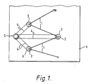
- figure 1 is a diagram of a manipulator arm on board a spacecraft
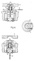
- figures 3 to 5 are various views of three retaining device embodiments.
- Figure 1 shows very diagrammatically a space craft cargo bay containing a manipulator arm made up of sections 1 hinged together by motor driven joints 2.
- the joints 2 are gripped to retain the arm in its stowed position by retaining devices 3 each comprising a rotary to linear motion converter driven by a respective cable drive 4 from a common motor drive 5.
- the motor drive and retaining devices are mounted on an end bulkhead 6 of the cargo bay.
- FIG. 2 shows two sectional elevations of one retaining device in the gripping and retracted positions respectively. It also shows an end view.
- the device comprises a flanged housing 20 fixed to bulkhead 6 and containing a drum 21 mounted for rotation in bearings 22.
- the drum 21 has an internal square-section thread in which is engaged a similarly threaded piston member 23.
- Hinged to upstanding lugs 24 are four gripping members 25 which are also coupled to piston member 23 via links 26.
- the gripping members 25 rotate up and out and then a little way down again to securely retain the joint, this joint being provided with an appropriate recess 27 for receiving the gripping members.
- the drum 21 is rotated so as to linearly move piston 23, by a cable (not shown) wound around the drum and led off to the common drive motor 5.
- the two gripping members 30 are hinged to the linearly movable piston member 31 and coupled via links 32 to the fixed upstanding lugs.
- the arrangement and action of the device is otherwise like that of the figure 2 device.
- the linearly movable output member 40 of a ball-screw 41 driven by cable 42 is connected to an inner piston 43 which slides in an outer piston 44 which itself slides in fixed housing/support member 45.
- Gripping members 46 are hinged to inner piston 43 and engage piston 44 ahead of it until this is stopped by locating shoulder 47.
- Coilspring 48 then shortens and gripping members 46 are protruded laterally to grip joint 2.
Landscapes
- Engineering & Computer Science (AREA)
- Remote Sensing (AREA)
- Aviation & Aerospace Engineering (AREA)
- Robotics (AREA)
- Mechanical Engineering (AREA)
- Manipulator (AREA)
Abstract
Description
- This invention relates to retaining devices, more particularly but not exclusively a retaining device, and and arrangement of such devices, for retaining an articulated manipulator arm, such as might be provided on a spacecraft for example, in its stowed position.
- It is proposed that the Hermes spacecraft should carry an articulated manipulator arm comprising a series of elongate portions joined one to another by hinge joints. When stowed, the portions of the arm lie alongside one another and alongside a cargo bay bulkhead. The arm must be strongly retained when stowed because of the large forces to which it will be subjected during launch and retrieval. It cannot be guaranteed that, after use, the arm can be returned very precisely to any particular stowed position. An object of the invention is to provide an appropriate retaining device and arrangement of such devices for carrying out this task.
- According to one aspect of the invention, there is provided a retaining device comprising two relatively linearly movable members, a linear actuator coupled to the members for producing said relative linear movement thereof, and at least one gripping member having a lever portion engaging said members for said relative linear movement of the relatively linearly movable members to produce movement of the gripping member in the direction of said linear movement and in a direction lateral thereto.
- According to a second aspect of the invention, there is provided a plurality of retaining devices as described above and mounted for gripping respective portions of apparatus to be retained, the actuator of each device comprising a rotary to linear motion converting device and all these converting devices being coupled to a common drive for rotating a rotatable member thereof.
- In the drawings, given by way of example, figure 1 is a diagram of a manipulator arm on board a spacecraft, and figures 3 to 5 are various views of three retaining device embodiments.
- Figure 1 shows very diagrammatically a space craft cargo bay containing a manipulator arm made up of sections 1 hinged together by motor driven
joints 2. Thejoints 2 are gripped to retain the arm in its stowed position byretaining devices 3 each comprising a rotary to linear motion converter driven by arespective cable drive 4 from acommon motor drive 5. The motor drive and retaining devices are mounted on anend bulkhead 6 of the cargo bay. - Figure 2 shows two sectional elevations of one retaining device in the gripping and retracted positions respectively. It also shows an end view. The device comprises a flanged
housing 20 fixed tobulkhead 6 and containing a drum 21 mounted for rotation inbearings 22. The drum 21 has an internal square-section thread in which is engaged a similarly threadedpiston member 23. Hinged to upstandinglugs 24 are four grippingmembers 25 which are also coupled topiston member 23 vialinks 26. As the piston moves up towardsmanipulator arm joint 23, the grippingmembers 25 rotate up and out and then a little way down again to securely retain the joint, this joint being provided with anappropriate recess 27 for receiving the gripping members. The drum 21 is rotated so as to linearly movepiston 23, by a cable (not shown) wound around the drum and led off to thecommon drive motor 5. - In the second embodiment shown in figure 3, the two gripping
members 30 are hinged to the linearlymovable piston member 31 and coupled vialinks 32 to the fixed upstanding lugs. The arrangement and action of the device is otherwise like that of the figure 2 device. - In figure 4, the linearly
movable output member 40 of a ball-screw 41 driven bycable 42 is connected to aninner piston 43 which slides in anouter piston 44 which itself slides in fixed housing/support member 45. Grippingmembers 46 are hinged toinner piston 43 and engagepiston 44 ahead of it until this is stopped by locatingshoulder 47. Coilspring 48 then shortens and grippingmembers 46 are protruded laterally togrip joint 2.
Claims (3)
Applications Claiming Priority (1)
| Application Number | Priority Date | Filing Date | Title |
|---|---|---|---|
| GB8628628A GB2202572B (en) | 1986-12-01 | 1986-12-01 | Retaining device |
Publications (2)
| Publication Number | Publication Date |
|---|---|
| EP0325821A2 true EP0325821A2 (en) | 1989-08-02 |
| EP0325821A3 EP0325821A3 (en) | 1990-03-21 |
Family
ID=10608215
Family Applications (1)
| Application Number | Title | Priority Date | Filing Date |
|---|---|---|---|
| EP88300601A Withdrawn EP0325821A3 (en) | 1986-12-01 | 1988-01-26 | Retaining device |
Country Status (2)
| Country | Link |
|---|---|
| EP (1) | EP0325821A3 (en) |
| GB (1) | GB2202572B (en) |
Cited By (2)
| Publication number | Priority date | Publication date | Assignee | Title |
|---|---|---|---|---|
| CN104626156A (en) * | 2015-01-07 | 2015-05-20 | 北京控制工程研究所 | Quick disassembling and assembling connector for spatial operation without driving source |
| CN111776255A (en) * | 2020-06-24 | 2020-10-16 | 南京理工大学 | A mechanical rope net pressing and releasing mechanism |
Families Citing this family (5)
| Publication number | Priority date | Publication date | Assignee | Title |
|---|---|---|---|---|
| JPH0748384Y2 (en) * | 1990-07-11 | 1995-11-08 | 株式会社安川電機 | Robot tool changer |
| JP5569150B2 (en) * | 2010-05-31 | 2014-08-13 | 株式会社Ihi | Satellite mounted system |
| JP6051101B2 (en) * | 2013-05-20 | 2016-12-27 | 川崎重工業株式会社 | Space debris removal device fixing device using extension spring, and space debris removal device including the same |
| CN104176279B (en) * | 2014-08-15 | 2016-03-09 | 哈尔滨工业大学 | A kind of noncooperative target capture mechanism |
| DE102019119657B4 (en) * | 2019-07-19 | 2021-03-04 | Schunk Gmbh & Co. Kg Spann- Und Greiftechnik | Tool changer for a robot and changing system therefor |
Family Cites Families (9)
| Publication number | Priority date | Publication date | Assignee | Title |
|---|---|---|---|---|
| GB997748A (en) * | 1963-10-25 | 1965-07-07 | Adams Rite Mfg Company | Lock mechanism |
| US3525483A (en) * | 1968-01-17 | 1970-08-25 | North American Rockwell | Deployment mechanism |
| CH522270A (en) * | 1970-09-30 | 1972-06-15 | Bbc Brown Boveri & Cie | Gripping device for nuclear reactor loading machine |
| IT950192B (en) * | 1971-03-19 | 1973-06-20 | Kraftwerk Union Ag | PRESSURE RESISTANT JOINT FOR PRESSURE VESSELS OF NUCLEAR REACTORS |
| FR2340798A1 (en) * | 1976-02-13 | 1977-09-09 | Polymatic Sa | IRREVERSIBLE CLAMP HEAD WITH FLOATING HITCH AND QUICK DISASSEMBLY |
| CH622837A5 (en) * | 1977-12-06 | 1981-04-30 | Saurer Ag Adolph | |
| DE3211908A1 (en) * | 1982-03-31 | 1983-10-13 | Teldix Gmbh, 6900 Heidelberg | Device for locking an element cardanically mounted on a fixed housing |
| NL8400362A (en) * | 1984-02-06 | 1985-09-02 | Fokker Bv | DEVICE FOR HOLDING OR RELEASING SOLAR PANELS OF A SPACE VESSEL. |
| IT1210110B (en) * | 1984-07-09 | 1989-09-06 | Tecnomare Spa | REVERSIBLE MECHANICAL JOINT FOR TENSION ANCHORAGES. |
-
1986
- 1986-12-01 GB GB8628628A patent/GB2202572B/en not_active Expired - Lifetime
-
1988
- 1988-01-26 EP EP88300601A patent/EP0325821A3/en not_active Withdrawn
Cited By (3)
| Publication number | Priority date | Publication date | Assignee | Title |
|---|---|---|---|---|
| CN104626156A (en) * | 2015-01-07 | 2015-05-20 | 北京控制工程研究所 | Quick disassembling and assembling connector for spatial operation without driving source |
| CN104626156B (en) * | 2015-01-07 | 2016-05-04 | 北京控制工程研究所 | A kind of without drive source spatial operation fast assembling-disassembling interface |
| CN111776255A (en) * | 2020-06-24 | 2020-10-16 | 南京理工大学 | A mechanical rope net pressing and releasing mechanism |
Also Published As
| Publication number | Publication date |
|---|---|
| GB8628628D0 (en) | 1987-01-07 |
| EP0325821A3 (en) | 1990-03-21 |
| GB2202572A (en) | 1988-09-28 |
| GB2202572B (en) | 1990-09-19 |
Similar Documents
| Publication | Publication Date | Title |
|---|---|---|
| US4123020A (en) | VTOL launching and retrieval systems | |
| US4334816A (en) | Device and method for assembling large space structures | |
| US4766775A (en) | Modular robot manipulator | |
| EP1284843B1 (en) | Actuation system for highly underactuated gripping mechanism | |
| US3631737A (en) | Remote control manipulator for zero gravity environment | |
| US5501498A (en) | Methods and apparatus for mechanically intelligent grasping | |
| US4831531A (en) | System for the performance of activity in space | |
| US4643473A (en) | Robotic mechanical hand | |
| US3268091A (en) | Reaction thrust operated manipulator | |
| RU138497U1 (en) | DEVICE FOR DISPOSING SPACE DEBR FROM USE OF USEFUL LOADS | |
| US4173324A (en) | Coupling device for moving vehicles | |
| CA1049586A (en) | Module exchanger systems | |
| EP0325821A2 (en) | Retaining device | |
| US5131706A (en) | Straight line gripper tool and changer | |
| CN116552830B (en) | Multi-mode rigid-flexible coupling modular space capture manipulator | |
| Feng et al. | Design schemes and comparison research of the end-effector of large space manipulator | |
| US5285484A (en) | Remote control apparatus for maintaining in-vessel components in a structure having an inner torus space | |
| US12042933B2 (en) | Nested linear stroke multipliers for robot manipulators | |
| EP0229185B1 (en) | Industrial robot | |
| Stieber et al. | Overview of the mobile servicing system for the international space station | |
| JPH0158037B2 (en) | ||
| RU2051058C1 (en) | Vehicle for movement along ferromagnetic surfaces | |
| US3520496A (en) | Serpentuator | |
| SU1119837A1 (en) | Industrial robot | |
| RU2167083C1 (en) | Device for motion of cargoes mainly beyond spacecraft kept in orbit |
Legal Events
| Date | Code | Title | Description |
|---|---|---|---|
| PUAI | Public reference made under article 153(3) epc to a published international application that has entered the european phase |
Free format text: ORIGINAL CODE: 0009012 |
|
| 17P | Request for examination filed |
Effective date: 19880202 |
|
| AK | Designated contracting states |
Kind code of ref document: A2 Designated state(s): DE FR NL |
|
| PUAL | Search report despatched |
Free format text: ORIGINAL CODE: 0009013 |
|
| AK | Designated contracting states |
Kind code of ref document: A3 Designated state(s): DE FR NL |
|
| 17Q | First examination report despatched |
Effective date: 19910531 |
|
| RAP3 | Party data changed (applicant data changed or rights of an application transferred) |
Owner name: BRITISH AEROSPACE PUBLIC LIMITED COMPANY |
|
| STAA | Information on the status of an ep patent application or granted ep patent |
Free format text: STATUS: THE APPLICATION IS DEEMED TO BE WITHDRAWN |
|
| 18D | Application deemed to be withdrawn |
Effective date: 19920428 |