EP0325835A1 - Dispositif d'encliquetage mécanique fonctionnant par gravité et traction - Google Patents
Dispositif d'encliquetage mécanique fonctionnant par gravité et traction Download PDFInfo
- Publication number
- EP0325835A1 EP0325835A1 EP88309735A EP88309735A EP0325835A1 EP 0325835 A1 EP0325835 A1 EP 0325835A1 EP 88309735 A EP88309735 A EP 88309735A EP 88309735 A EP88309735 A EP 88309735A EP 0325835 A1 EP0325835 A1 EP 0325835A1
- Authority
- EP
- European Patent Office
- Prior art keywords
- collet
- fishing neck
- latch
- collet fingers
- pulling
- Prior art date
- Legal status (The legal status is an assumption and is not a legal conclusion. Google has not performed a legal analysis and makes no representation as to the accuracy of the status listed.)
- Ceased
Links
- 230000006835 compression Effects 0.000 claims description 16
- 238000007906 compression Methods 0.000 claims description 16
- 230000000452 restraining effect Effects 0.000 claims description 4
- 230000007246 mechanism Effects 0.000 abstract description 33
- 230000000694 effects Effects 0.000 description 10
- 238000004519 manufacturing process Methods 0.000 description 6
- 210000001364 upper extremity Anatomy 0.000 description 3
- 238000009530 blood pressure measurement Methods 0.000 description 2
- 238000000605 extraction Methods 0.000 description 2
- 239000012530 fluid Substances 0.000 description 2
- 230000001939 inductive effect Effects 0.000 description 2
- 210000003141 lower extremity Anatomy 0.000 description 2
- 241001640034 Heteropterys Species 0.000 description 1
- 230000009471 action Effects 0.000 description 1
- 238000004891 communication Methods 0.000 description 1
- 238000003780 insertion Methods 0.000 description 1
- 230000037431 insertion Effects 0.000 description 1
- 230000003993 interaction Effects 0.000 description 1
- 238000000034 method Methods 0.000 description 1
- 239000003209 petroleum derivative Substances 0.000 description 1
- 230000036316 preload Effects 0.000 description 1
- 230000008569 process Effects 0.000 description 1
- 238000000926 separation method Methods 0.000 description 1
- 239000007787 solid Substances 0.000 description 1
Images


Classifications
-
- E—FIXED CONSTRUCTIONS
- E21—EARTH OR ROCK DRILLING; MINING
- E21B—EARTH OR ROCK DRILLING; OBTAINING OIL, GAS, WATER, SOLUBLE OR MELTABLE MATERIALS OR A SLURRY OF MINERALS FROM WELLS
- E21B31/00—Fishing for or freeing objects in boreholes or wells
- E21B31/12—Grappling tools, e.g. tongs or grabs
- E21B31/18—Grappling tools, e.g. tongs or grabs gripping externally, e.g. overshot
-
- E—FIXED CONSTRUCTIONS
- E21—EARTH OR ROCK DRILLING; MINING
- E21B—EARTH OR ROCK DRILLING; OBTAINING OIL, GAS, WATER, SOLUBLE OR MELTABLE MATERIALS OR A SLURRY OF MINERALS FROM WELLS
- E21B23/00—Apparatus for displacing, setting, locking, releasing or removing tools, packers or the like in boreholes or wells
- E21B23/02—Apparatus for displacing, setting, locking, releasing or removing tools, packers or the like in boreholes or wells for locking the tools or the like in landing nipples or in recesses between adjacent sections of tubing
Definitions
- This invention is related to the subject matter of U.S. Patent No. 4,687,055, issued to Henry H. Leggett on August 18, 1987 and entitled "WIRE-LINE CONTROLLED DOWN-HOLE SHUT-IN TOOL FOR WELLS".
- This invention relates generally to downhole equipment for controlling the flow of fluids in wells and for conducting various other activities in wells either on a temporary or permanent basis. More specifically, the present invention is directed to a latching mechanism for well tools which permits the repeatable, latching onto and unlatching from downhole tools by utilizing the dead weight of a tool string and tension of the tool string respectively.
- well tools are intended to remain more or less permanently located within the tubing string of a well and in other cases, well tool are intended to be positioned in a mandrel of the tubing string for only a limited period of time for a specific purpose.
- Downhole shut-in tools may be permanently installed in wells and are operative within the tubing string of the well to temporarily shut-in the well so that certain activities such as bottom hole pressure measurement can take place. Regardless of the temporary or permanent nature of well tools, it is typically desirable to provide efficient mechanisms for traversing the tubing string of a well, latching onto operative components of the downhole tool and then shifting the downhole tool mechanism to a desired position.
- Downhole well tools may be operated by controlling them with a running tool string which may be in the form of a wireline controlled tool running system or may conveniently take the form of a solid tool operating string such as may be composed of interconnected sections of tubing.
- a running tool string which may be in the form of a wireline controlled tool running system or may conveniently take the form of a solid tool operating string such as may be composed of interconnected sections of tubing.
- downhole tools are serviced by wireline tool actuation systems.
- Well service tools may also be employed which are pumped through the tubing string to achieve upward or downward movement for latching to, operating and releasing from downhole well tools.
- the latching device also permits efficient unlatching simply through upward application of force from the service tool string.
- the mechanical latching and unlatching concept of this invention may be incorporated with a downhole tool assembly having either an internal or external fishing neck configuration as discussed in detail herein.
- the embodiment with an external fishing neck consists of four basic components, i.e. a collet, a fishing neck over which the collet locates, a cylindrical collet retainer and a retainer spring.
- the fishing neck extends from the uppermost portion of a downhole well tool assembly of any suitable character, such as a downhole shut-in tool of the type set forth in U.S. Patent No. 4,687,055 for example.
- the fishing neck is positioned upright and in centralized manner inside the housing structure of the mandrel within which the well tool is located.
- the fishing neck is of sufficiently small diameter as to be received within a latching collet which is lowered into assembly with the latching neck by means of a running tool string such as a wireline tool string.
- a running tool string such as a wireline tool string.
- the dead weight of the running tool string is employed to latch the collet in place over a pulling flank of the fishing neck.
- a spring urged collet retainer secures the collet fingers against release from the pulling flank of the fishing neck.
- the down hole tool may be appropriately operated by the dead weight of the running tool system. If the down hole tool is operated by upward force, the wireline running tool system is reversed, thereby applying a linear upward force or tension to the collet which in turn applies upward force to the fishing neck and the downhole tool located therebelow.
- Separation of the running or service tool system from the fishing neck of the downhole tool is accomplished simply by applying additional upward linear force to the wireline controlled service tool which is sufficiently great to cause releasing of the latch mechanism.
- the collet will automatically release from the pulling flank of the fishing neck upon application of sufficient force to the fishing neck to overcome the compression of retainer spring of the fishing neck assembly.
- the fishing neck assembly and the collet will automatically return to the original configurations thereof and may repeatedly be latched and unlatched without requiring resetting or other changes in the latching system as is typical with downhole latches that are commercially available at the present time.
- the invention incorporates a second or alternative embodiment which is in the form of an internal latch which employs the same basic components as described above.
- the downhole service tool incorporates a tubular latch actuator member forming the lower portion of the running tool string and defining a pulling flank at the lower end thereof.
- the latch assembly incorporates an upstanding, fishing neck in the form of an upstanding central guide member which is connected to the upper portion of the downhole tool.
- a latch retainer element is disposed in surrounding spaced relation with the fishing neck and is urged to a set or latching position by a compression spring.
- a collet Surrounding the central guide member and positioned between the fishing neck and latch retainer is a collet which is urged upwardly by a smaller compression spring and which is linearly movable relative to the fishing neck and latch retainer.
- the latch retainer forms internal recesses for receiving the resilient fingers of the collet when the collet fingers are expanded radially outwardly as the running tool assembly is latched to and is released from the internal fishing neck assembly.
- the second or alternative embodiment of this invention functions in the same manner as the external fishing neck assembly to provide repeatable latching and unlatching. latching of the running tool string to the internal fishing neck is accomplished by downward force of a lower tubular latch actuator member which is induced by the dead weight of the running tool string. Release of the running tool string from the internal fishing neck is accomplished simply and efficiently by application of upward force to the running tool string such as by the wireline or other connecting system extending from the running tool string to the surface equipment.
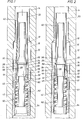
- a repeatable mechanical latching mechanism shown generally at 10 is located within the upper portion of a downhole tool mandrel 12 which may contain any appropriate type of down hole tool, for example, such as a permanently installed down hole shut-in tool of the general nature set forth in U.S. Patent 4,687,055.
- the downhole tool mandrel is incorporated within the lower part of a production tubing string extending from the surface to the level at or near a production zone intersected by the well bore of a well for producing petroleum products.
- the upper end of the downhole tool tool mandrel 12 will typically be provided with a threaded connection for securing the mandrel to the lower threaded end of the tubing string.
- a section of tubing string may also be connected to the lower end of the mandrel if desired.
- the downhole tool mandrel 12 further defines an internal passage 14 which communicates with the flow passage of the tubing string and forms an internal chamber 16 within which the downhole tool assembly is located.
- an internal shoulder 18 which serves as a stop shoulder for restricting upward movement of the latch mechanism as will be discussed hereinbelow.
- a running tool string is provided which is typically operated by wireline or which may take any other suitable form without departing from the sprit or scope of this invention.
- the running tool string has as its lower end a tubular member 20 defining a cylindrical collet 22 at its lower end, the collet forming a component part of the latch assembly.
- the collet 22 defines a plurality of flexible collet fingers 24 each collet finger defining an internal pulling shoulder 26.
- the lower ends of each of the collet fingers 24 also defined internal and external tapered guide surfaces 28 and 30 to assist in centralizing the collet as the running tool string moves downwardly and insuring proper reception of the collet over the fishing neck as the collet reaches the downhole tool assembly.
- the downhole tool is provided at its upper end with other component parts of the latch mechanism as illustrated in Figs. 1-3.
- the latch mechanism incorporates a fishing neck 32 which defines an enlargement 34 forming a latching profile having a downwardly facing abruptly tapered pulling shoulder or pulling flank 36 and an upwardly facing gradually tapered collet expansion and guide surface 38.
- An upper portion 40 of the fishing neck projects upwardly into the passage 14 of the mandrel and is maintained in substantially centralized position within the passage to enable the collet 22 to be efficiently received over the fishing neck in the manner shown in Figs. 1-3.
- the lower portion of the fishing neck is surrounded by a movable latch retainer 42 of generally cylindrical form and which is provided with a cylindrical collet retainer extension 44 at the upper extremity thereof.
- a movable latch retainer 42 of generally cylindrical form and which is provided with a cylindrical collet retainer extension 44 at the upper extremity thereof.
- an internal stop flange 46 which is adapted to seat against a downwardly facing circular stop shoulder 48 of the fishing neck 32.
- a compression spring member 50 is disposed about a reduced diameter portion 52 of the fishing neck 32 with respective upper and lower ends thereof in abutting engagement with the internal stop flange 46 and a lower circular spring retainer shoulder 54 defined by the lower portion of the fishing neck or the upper portion of the down hole tool as the case may be.
- the fishing neck 32 with its uppermost extension 40 will be positioned in upstanding, centralized relation within the internal chamber 16 and with the upper extension 40 centralized within the passage 14 of the mandrel as shown in Fig. 1.
- the enlargement 34 of the fishing neck will be positioned well below the level of the internal shoulder 18 of the mandrel.
- a running tool string with the tubular member 20 attached to the lower end thereof is then lowered through the tubing such as by a wireline tool running system.
- the collet 22 will be received over the upper extension 40 of the fishing neck and will move downwardly until the tapered guide surfaces 28 of the collet fingers 24 contact the gradually tapered collet guide and expansion surface 38.
- the collet expansion surface will both centralize the collet within the internal chamber of the mandrel and relative to the fishing neck. Further downward movement of the collet by the dead weight of the running tool assembly will cause the collet expansion surface 38 to function in cam-like manner to induce radial expansion of the collet fingers 24. The collet fingers 24 will be forced radially outward under the applied dead weight load of the running tool until the collet fingers are efficiently expanded so as to allow the collet to pass over the enlargement 34.
- the collet fingers are prevented from expanding and thereby maintain the internal pulling shoulders 26 in positive locking interengagement with the external pulling flank 36 of the fishing neck.
- the wireline running tool then may be appropriately manipulated upwardly or downwardly for application of controlling force to the downhole tool for appropriate operation thereof. It should be noted that the latch mechanism will not automatically unlatch and release from the downhole tool until upward linear force of a predetermined magnitude is applied.
- FIG. 4-6 there is disclosed an internal mechanical latch assembly for downhole tools which functions in the same general manner as described above in connection with Figs. 1-3.
- the apparatus of Figs. 4-6 will become latched by downward movement of a tubular member responsive to the dead weight of a running tool system. Further, the mechanism will become unlatched simply upon upward linear movement of the tubular member such as by tension applied by the running tool. Typically upward tension will be induced by a wireline system.
- a production tubing string will be provided with a downhole tool mandrel 62 forming an internal chamber 64 which is in communication with a passage 66 extending to the passage of the tubing string to which the mandrel is connected.
- the mandrel forms a tapered internal stop shoulder 68 at the upper extremity of the chamber 64.
- a wireline running tool string is provided at its lower extremity with a tubular latch actuator member having an external enlargement 72 at its lower extremity forming an upwardly directed, tapered external pulling shoulder or flank 74.
- an internal latch retainer 76 which surrounds a fishing neck 82 that is connected as the upper extremity of a downhole tool such as a downhole shut-in tool also located within the mandrel.
- the latch retainer forms a component part of the fishing neck by providing pulling surfaces and latch release recesses.
- the upper end of the latch retainer 76 forms a tapered circular surface 78 adapted for contact with the downwardly directed stop surface 68 when the latch retainer is moved upwardly to its full extent as shown in Fig. 6.
- the latch retainer defines an internal chamber 80 which receives the fishing neck 82 which is in the form of an elongated pin.
- the latch retainer member 76 is positioned and stabilized relative to the fishing neck 82 by means of a compression spring which encircles a reduced diameter portion 86 of the fishing neck member and is positioned with its upper and lower ends in abutting relation respectively with an internal flange 88 of the latch retainer and a spring retainer surface 90 formed by the lower portion 92 of the fishing neck or the upper end of the downhole tool to which the fishing neck is connected.
- a compression spring which encircles a reduced diameter portion 86 of the fishing neck member and is positioned with its upper and lower ends in abutting relation respectively with an internal flange 88 of the latch retainer and a spring retainer surface 90 formed by the lower portion 92 of the fishing neck or the upper end of the downhole tool to which the fishing neck is connected.
- the fishing neck is provided at the upper end of a downhole tool mechanism which is located within the mandrel and is positioned in centralized, spaced relation within the mandrel.
- the upper end of the fishing neck 82 forms a tapered guide surface 94 which is adapted to be engaged by the internal tapered surface 96 at the lower end of the latch actuator 70 to thereby efficiently guide the latch actuator into properly received assembly about the fishing neck and internally of the latch retainer member.
- the latch retainer 76 is formed internally to define upper and lower internal cavities or recesses 96 and 98 which are adapted to receive the collet fingers of a collet member 100 which surrounds the fishing neck 82.
- the collet member 100 defines upwardly directed collet fingers 102 each defining internal enlargements which project radially inwardly therefrom.
- the enlargements 104 of the collet fingers each define upwardly and downwardly tapered surfaces 106 and 108.
- the upwardly directed tapered surfaces 106 of the resilient collet fingers form guide surfaces or cam surfaces which induce radial expansion of the collet fingers upon passage of the external enlargement 72 of the latch actuator into the collet.
- the downwardly directed lower tapered surfaces 108 of the collet fingers function as pulling surfaces for restraining interengagement with the pulling flank 74 of the latch actuator 70.
- the fishing neck forms an external stop shoulder 110 which is disposed for engagement by the lower end of the latch actuator to limit downward movement of the latch actuator over the fishing neck.
- the collet member 100 forms opposed external slots 112 and 114 that receive respective end portions of a collet control pin member 116 which extends through a transverse passage in the fishing neck 82.
- the collet member 100 is movable relative to the fishing neck 82 within limits defined by the length of the opposed slots 112 and 114.
- a compression spring 118 is positioned about the fishing neck with its upper ends in force transmitting engagement with the lower end 120 of the collet member 100 and a spring retainer surface 122 formed by a flange 124 of the fishing neck.
- the latch retainer 76 and the fishing neck 82 are positioned in the manner shown in Fig. 4 during downward insertion of the latch actuator 70 by the dead weight of the running tool.
- the latch actuator is moved downwardly along with the wireline tool until it reaches the level of the mandrel 62.
- its inner tapered surface 96 will first contact the upwardly directed tapered surface 94 of the fishing neck thus causing centralization of the latch actuator and causing it to slide over the external surface of the fishing neck.
- the latch actuator moves into the chamber 80 defined by the fishing neck 76 and comes into contact with the upper end of the collet member 100.
- the latch actuator will force the collet member 100 downwardly by further compressing the collet spring 118.
- the spring fingers 102 of the collet come into registry with the recess 98 a camming activity will occur between the latch actuator and the tapered inner surfaces 106 of the collet fingers 102 thus causing the resilient collet fingers to be urged radially outwardly, thereby allowing the external enlargement 72 of the latch actuator to move downwardly to a position within the collet such as shown in Fig. 5.
- Latching and unlatching of the latch actuator 70 with respect to the latch mechanism may occur repeatedly without any requirement for resetting the apparatus.
- the downhole tool operation will have been carried out in simple and efficient manner such as through the use of wireline controlled equipment. Operation of the downhole tool may be achieved as many times as is appropriate for proper service and operation of the well production system without necessitating removal of the tubing string from the well.
Landscapes
- Life Sciences & Earth Sciences (AREA)
- Engineering & Computer Science (AREA)
- Geology (AREA)
- Mining & Mineral Resources (AREA)
- Physics & Mathematics (AREA)
- Environmental & Geological Engineering (AREA)
- Fluid Mechanics (AREA)
- General Life Sciences & Earth Sciences (AREA)
- Geochemistry & Mineralogy (AREA)
- Marine Sciences & Fisheries (AREA)
Applications Claiming Priority (2)
| Application Number | Priority Date | Filing Date | Title |
|---|---|---|---|
| US07/145,376 US4828023A (en) | 1988-01-19 | 1988-01-19 | Mechanical latching device operated by dead weight and tension |
| US145376 | 1998-09-01 |
Publications (1)
| Publication Number | Publication Date |
|---|---|
| EP0325835A1 true EP0325835A1 (fr) | 1989-08-02 |
Family
ID=22512828
Family Applications (1)
| Application Number | Title | Priority Date | Filing Date |
|---|---|---|---|
| EP88309735A Ceased EP0325835A1 (fr) | 1988-01-19 | 1988-10-17 | Dispositif d'encliquetage mécanique fonctionnant par gravité et traction |
Country Status (2)
| Country | Link |
|---|---|
| US (1) | US4828023A (fr) |
| EP (1) | EP0325835A1 (fr) |
Cited By (3)
| Publication number | Priority date | Publication date | Assignee | Title |
|---|---|---|---|---|
| WO2010115284A1 (fr) | 2009-04-09 | 2010-10-14 | Les Entreprises Parlec Ltée | Dispositif de verrouillage pour un dispositif de forage |
| WO2022082092A1 (fr) * | 2020-10-16 | 2022-04-21 | Schlumberger Technology Corporation | Loquet d'élévation par injection de gaz |
| US12560059B2 (en) | 2021-11-19 | 2026-02-24 | Schlumberger Technology Corporation | Gas lift latch |
Families Citing this family (11)
| Publication number | Priority date | Publication date | Assignee | Title |
|---|---|---|---|---|
| WO1994029567A1 (fr) * | 1993-06-16 | 1994-12-22 | Down Hole Technologies Pty. Ltd. | Systeme de remplacement in situ de moyens coupants pour un trepan de sondage |
| BR9406309A (pt) * | 1993-06-16 | 1996-01-02 | Down Hole Tech Pty Ltd | Sistema para substituição in situ de meois de corte em broca para perfurações de songadem |
| AU675551B2 (en) * | 1993-06-16 | 1997-02-06 | Down Hole Technologies Pty Ltd | System for in situ replacement of cutting means for a grounddrill |
| AU124096S (en) * | 1994-12-07 | 1995-07-14 | Down Hole Tech Pty Ltd | Drill bit finger |
| AU124522S (en) | 1994-12-15 | 1995-08-31 | Down Hole Tech Pty Ltd | Drill bit finger |
| AU125162S (en) | 1995-02-21 | 1995-11-13 | Down Hole Tech Pty Ltd | Cutting head |
| US5743344A (en) * | 1995-05-18 | 1998-04-28 | Down Hole Technologies Pty. Ltd. | System for in situ replacement of cutting means for a ground drill |
| AUPN505395A0 (en) * | 1995-08-28 | 1995-09-21 | Down Hole Technologies Pty Ltd | Tool for transporting cutting means to and from a ground drill |
| US9057230B1 (en) | 2014-03-19 | 2015-06-16 | Ronald C. Parsons | Expandable tubular with integral centralizers |
| JP7206208B2 (ja) | 2017-03-01 | 2023-01-17 | キャリア コーポレイション | コレットラッチ |
| CN114482898B (zh) * | 2020-10-27 | 2024-03-22 | 中国石油化工股份有限公司 | 变径台肩断裂抽油杆的打捞工具 |
Citations (5)
| Publication number | Priority date | Publication date | Assignee | Title |
|---|---|---|---|---|
| US4017113A (en) * | 1976-02-04 | 1977-04-12 | General Electric Company | Electrical cable overshot-grappling tool |
| GB2039310A (en) * | 1979-01-15 | 1980-08-06 | Baker Int Corp | Locking device for landing within a well conduit |
| US4295528A (en) * | 1980-06-16 | 1981-10-20 | Baker International Corporation | Selective lock with setting and retrieving tools |
| US4478279A (en) * | 1982-10-12 | 1984-10-23 | Hydril Company | Retrievable inside blowout preventer valve apparatus |
| US4687055A (en) * | 1986-04-07 | 1987-08-18 | Leggett Henry H | Wire-line controlled down-hole shut-in tool for wells |
Family Cites Families (18)
| Publication number | Priority date | Publication date | Assignee | Title |
|---|---|---|---|---|
| US2964942A (en) * | 1958-09-08 | 1960-12-20 | Shell Oil Co | Bottom-hole pressure testing apparatus |
| US3078923A (en) * | 1960-04-15 | 1963-02-26 | Camco Inc | Safety valve for wells |
| US3495659A (en) * | 1968-05-31 | 1970-02-17 | Schlumberger Technology Corp | Running apparatus for well tools |
| US3633669A (en) * | 1970-08-24 | 1972-01-11 | Exxon Production Research Co | Apparatus for running in and operation of valves and the like |
| US3853175A (en) * | 1971-11-30 | 1974-12-10 | Abegg & Reinhold Co | Remotely operated well safety valves |
| US3860066A (en) * | 1972-03-27 | 1975-01-14 | Otis Eng Co | Safety valves for wells |
| US4031955A (en) * | 1976-01-20 | 1977-06-28 | Baker Oil Tools, Inc. | Down hole inhibitor injector |
| US4105279A (en) * | 1976-12-16 | 1978-08-08 | Schlumberger Technology Corporation | Removable downhole measuring instruments with electrical connection to surface |
| US4340088A (en) * | 1980-06-09 | 1982-07-20 | Daniel Industries, Inc. | Pressure balanced safety valve for wells and flow lines |
| US4325431A (en) * | 1980-07-10 | 1982-04-20 | Ava International Corporation | Flow controlling apparatus |
| CH652437A5 (de) * | 1980-09-15 | 1985-11-15 | Haeny & Cie Ag | Verfahren und vorrichtung zum ermitteln des injektionsdruckes bei baulichen injektionen. |
| US4454913A (en) * | 1981-01-05 | 1984-06-19 | Schlumberger Technology Corporation | Safety valve system with retrievable equalizing feature |
| US4407363A (en) * | 1981-02-17 | 1983-10-04 | Ava International | Subsurface well apparatus |
| US4434847A (en) * | 1982-03-17 | 1984-03-06 | Ava International Corporation | Flow controlling apparatus |
| US4483397A (en) * | 1982-12-27 | 1984-11-20 | Hughes Tool Company | Method and apparatus for monitoring well tubing fluid |
| US4527631A (en) * | 1983-09-12 | 1985-07-09 | Ava International Corporation | Subsurface safety valve |
| US4557333A (en) * | 1983-09-19 | 1985-12-10 | Halliburton Company | Low pressure responsive downhole tool with cam actuated relief valve |
| US4524831A (en) * | 1983-12-27 | 1985-06-25 | Camco, Incorporated | Hydraulic controlled well valve |
-
1988
- 1988-01-19 US US07/145,376 patent/US4828023A/en not_active Expired - Lifetime
- 1988-10-17 EP EP88309735A patent/EP0325835A1/fr not_active Ceased
Patent Citations (5)
| Publication number | Priority date | Publication date | Assignee | Title |
|---|---|---|---|---|
| US4017113A (en) * | 1976-02-04 | 1977-04-12 | General Electric Company | Electrical cable overshot-grappling tool |
| GB2039310A (en) * | 1979-01-15 | 1980-08-06 | Baker Int Corp | Locking device for landing within a well conduit |
| US4295528A (en) * | 1980-06-16 | 1981-10-20 | Baker International Corporation | Selective lock with setting and retrieving tools |
| US4478279A (en) * | 1982-10-12 | 1984-10-23 | Hydril Company | Retrievable inside blowout preventer valve apparatus |
| US4687055A (en) * | 1986-04-07 | 1987-08-18 | Leggett Henry H | Wire-line controlled down-hole shut-in tool for wells |
Cited By (7)
| Publication number | Priority date | Publication date | Assignee | Title |
|---|---|---|---|---|
| WO2010115284A1 (fr) | 2009-04-09 | 2010-10-14 | Les Entreprises Parlec Ltée | Dispositif de verrouillage pour un dispositif de forage |
| US9140084B2 (en) | 2009-04-09 | 2015-09-22 | Les Entreprises Parlec Ltée | Locking device for a drilling device |
| WO2022082092A1 (fr) * | 2020-10-16 | 2022-04-21 | Schlumberger Technology Corporation | Loquet d'élévation par injection de gaz |
| GB2614660A (en) * | 2020-10-16 | 2023-07-12 | Schlumberger Technology Bv | Gas lift latch |
| US12129724B2 (en) | 2020-10-16 | 2024-10-29 | Schlumberger Technology Corporation | Gas lift latch |
| GB2614660B (en) * | 2020-10-16 | 2024-11-06 | Schlumberger Technology Bv | Gas lift latch |
| US12560059B2 (en) | 2021-11-19 | 2026-02-24 | Schlumberger Technology Corporation | Gas lift latch |
Also Published As
| Publication number | Publication date |
|---|---|
| US4828023A (en) | 1989-05-09 |
Similar Documents
| Publication | Publication Date | Title |
|---|---|---|
| US4828023A (en) | Mechanical latching device operated by dead weight and tension | |
| US3856081A (en) | Locking devices | |
| US4295528A (en) | Selective lock with setting and retrieving tools | |
| US4614233A (en) | Mechanically actuated downhole locking sub | |
| US3507329A (en) | Locating and anchoring device for well tools | |
| US5249630A (en) | Perforating type lockout tool | |
| US3863961A (en) | Latching device | |
| US5390735A (en) | Full bore lock system | |
| US4457368A (en) | Shearable no go insert for a well lock | |
| US6196309B1 (en) | Down hole pulling tool and method of use | |
| US3990510A (en) | Releasable well anchor tool | |
| US4558895A (en) | Pulling tool | |
| US4265306A (en) | Latch for well tools | |
| US4718488A (en) | Pump-out plug system for a well conduit | |
| US5613560A (en) | Wireline set, tubing retrievable well packer with flow control device at the top | |
| US4944345A (en) | Well device lock mandrel and running tool | |
| US5636694A (en) | Hydraulic power stroker for shifting of sliding sleeves | |
| CA2583922A1 (fr) | Outil de decentrage et systeme de mandrins selectif | |
| US5092402A (en) | Tubing end locator | |
| US7347269B2 (en) | Flow tube exercising tool | |
| US4883119A (en) | Mechanical latching device operated by dead weight and tension | |
| US2778433A (en) | Well tools | |
| US4554972A (en) | Well tool locking device | |
| US4379488A (en) | Latch for well tool | |
| US4962813A (en) | Well tool locking system for staggered bore |
Legal Events
| Date | Code | Title | Description |
|---|---|---|---|
| PUAI | Public reference made under article 153(3) epc to a published international application that has entered the european phase |
Free format text: ORIGINAL CODE: 0009012 |
|
| AK | Designated contracting states |
Kind code of ref document: A1 Designated state(s): DE FR GB IT NL |
|
| 17P | Request for examination filed |
Effective date: 19891125 |
|
| 17Q | First examination report despatched |
Effective date: 19910425 |
|
| STAA | Information on the status of an ep patent application or granted ep patent |
Free format text: STATUS: THE APPLICATION HAS BEEN REFUSED |
|
| 18R | Application refused |
Effective date: 19921019 |