EP0326008A2 - Procédé relatif à la vitesse d'extrusion dans l'extrusion inversée des billettes en laiton et analogues, et appareil à cet effet - Google Patents
Procédé relatif à la vitesse d'extrusion dans l'extrusion inversée des billettes en laiton et analogues, et appareil à cet effet Download PDFInfo
- Publication number
- EP0326008A2 EP0326008A2 EP89100817A EP89100817A EP0326008A2 EP 0326008 A2 EP0326008 A2 EP 0326008A2 EP 89100817 A EP89100817 A EP 89100817A EP 89100817 A EP89100817 A EP 89100817A EP 0326008 A2 EP0326008 A2 EP 0326008A2
- Authority
- EP
- European Patent Office
- Prior art keywords
- header
- extrusion
- axis
- brass
- billet
- Prior art date
- Legal status (The legal status is an assumption and is not a legal conclusion. Google has not performed a legal analysis and makes no representation as to the accuracy of the status listed.)
- Ceased
Links
Images


Classifications
-
- B—PERFORMING OPERATIONS; TRANSPORTING
- B21—MECHANICAL METAL-WORKING WITHOUT ESSENTIALLY REMOVING MATERIAL; PUNCHING METAL
- B21C—MANUFACTURE OF METAL SHEETS, WIRE, RODS, TUBES, PROFILES OR LIKE SEMI-MANUFACTURED PRODUCTS OTHERWISE THAN BY ROLLING; AUXILIARY OPERATIONS USED IN CONNECTION WITH METAL-WORKING WITHOUT ESSENTIALLY REMOVING MATERIAL
- B21C23/00—Extruding metal; Impact extrusion
- B21C23/02—Making uncoated products
- B21C23/20—Making uncoated products by backward extrusion
- B21C23/205—Making products of generally elongated shape
-
- B—PERFORMING OPERATIONS; TRANSPORTING
- B21—MECHANICAL METAL-WORKING WITHOUT ESSENTIALLY REMOVING MATERIAL; PUNCHING METAL
- B21C—MANUFACTURE OF METAL SHEETS, WIRE, RODS, TUBES, PROFILES OR LIKE SEMI-MANUFACTURED PRODUCTS OTHERWISE THAN BY ROLLING; AUXILIARY OPERATIONS USED IN CONNECTION WITH METAL-WORKING WITHOUT ESSENTIALLY REMOVING MATERIAL
- B21C23/00—Extruding metal; Impact extrusion
- B21C23/21—Presses specially adapted for extruding metal
- B21C23/218—Indirect extrusion presses
Definitions
- This invention relates to a method for improving the backward extrusion rate of brass billets.
- a well-recognized requirement is, in the specific field of brass billet backward extruding as performed on a horizontal extrusion axis press, that a surface layer be removed from the billet if a good quality product is to be attained.
- billets develop a surface layer which usually includes impurities and cracks and must, therefore, be removed.
- brass billets require that the surface layer be removed and discarded as the billet is being extruded.
- an extrusion die Located at the remote end opening of the tubular case from the billet-loading end opening is an extrusion die which, as the case is being driven forward, abuts against the tubular header, thus extruding the billet thereinto.
- the outside diameter of the die is made smaller than the inside diameter of the case, but larger than the outside diameter of the header. Accordingly, as the case is driven forward over the header, the surface layer of the billet will move past the die through the space left between the die and the case inside wall, thus forming for the latter an inside liner of sort.
- the billet is not fully extruded through the die because the tubular case is stopped on the die approaching the billet-loading end opening of the case. There is left over, accordingly, a substantially disk-like end portion of the billet, which is then cut off by means of shears.
- a handling means is therefore to be provided for setting a die at the case inlet, pick it up at the opposite outlet end after the extrusion, replace it with another die, and repeat this course of operations to extrude each of the billets.
- the problem underlying this invention is to provide a method for improving the backward extrusion rate of brass billets and the like.
- a method as indicated being characterized in that it comprises the steps of providing two parallel tubular headers having respective extrusion dies attached thereto and being mounted on slides driven in a guided manner along perpendicular directions to the extrusion axis, setting a first of said headers at an operative position for extrusion aligned to said axis and a second of said headers at an inoperative position for extrusion alongside said axis, extruding a billet through the die on said first header with formation of a residual brass jacket around said header, on completion of said billet extruding step, taking the first header to its inoperative position for extrusion and the second header to its operative position, and clearing the first header at its inoperative position of said brass jacket.
- the step of clearing one header of its respective residual brass jacket is carried out simultaneously with the step of extruding a billet with the other header.
- the numeral 1 comprehensively designates a horizontal extrusion press having a horizontal extrusion axis X-X and being intended for backward extruding billets 2 and the like, specifically brass billets.
- the press 1 comprises a hydraulic unit 3 which consists of a primary assembly 4 including a cylinder 5 and piston 6 extending along the axis X-X and being flanked by two secondary cylinder/piston assemblies 7, 8 connected to the primary assembly by a cross-member 9 laid perpendicular to the axis X-X.
- Indicated at 10 is a plate extending in a normal plane to the horizontal extrusion axis X-X and confronting the cross-member 9, which is arranged to be movable toward and away from the plate 10 under the drive from the hydraulic unit 3.
- Two parallel guides respectively an upper one 13 and lower one 14, are mounted to the plate 10 and extend along a first horizontal direction Y-Y, perpendicular to the axis X-X, with the passageway 11 open between said guides.
- Indicated at 15 is a fixture mounted for sliding movement on the guides 13, 14 and being guided along the first direction Y-Y by the drive from a motive means 16 consisting of a hydraulic cylinder carried on one side 10a of the plate 10.
- a shelf 17 having a substantially V-shaped cross-section is mounted to the fixture 15 and adapted to hold a billet 2; in addition, there is provided a pusher 18, located at the shelf 17, which extends in a parallel direction to the axis X-X and acts on a billet 2 placed on the shelf 17.
- the press 1 comprises, on one side 10b of the plate 10, remote from the side 10a, an elevator device generally indicated at 19 and consisting basically of two horizontal brackets overlying each other at a distance apart, respectively an upper one 20 and a lower one 21, which are mounted on a carriage movable in a guided fashion along vertical guides 22 formed on an upright 23.
- the reference numeral 24 designates an upstanding hydraulic cylinder supported on the base of the upright 23 and constituting a motive means adapted to act on said carriage at the lower bracket 21 and drive the carriage along the guides 22 in a second direction W-W perpendicular to the first direction Y-Y.
- brackets 20 and 21 are provided with guides lying parallel to the first direction Y-Y, and that the carriage can be driven from a bottom position (see Figure 2), where the guide of the upper bracket 20 is aligned to the lower guide 14 of the plate 10, to a top position where the guide of the lower bracket 21 is aligned to said guide 14.
- the press 1 further comprises two tubular plungers or headers 25 and 26 which are identical with each other and extend in a parallel direction to the horizontal extrusion axis X-X each being carried cantilever-fashion on a respective slide 27, 28.
- Affixed to one end of each of the headers 25, 26 confronting the cross-member 9 is a respective ring die 29, 30, having a larger outside diameter than the outside diameter of the header.
- the slide 27 for the first header 25 is mounted on the guides 13 and 14 in an operative position for extrusion, where the first header 25 is aligned to the extrusion axis X-X.
- the slide 28 of the second header 26 is instead mounted on the guide on the upper bracket 20 with the carriage at its bottom position.
- the second header 26 is located in an inoperative position, alongside the horizontal extrusion axis X-X at the same level as the operative extrusion position.
- Indicated at 31 is a latching means formed on one side of the fixture 15 and on a confronting side of each slide 27, 28 for detachably associating a slide with said fixture and, by means of the motive means 16, drive it perpendicularly to the axis X-X, along the first direction Y-Y from the operative position to the inoperative position, and vice versa, as explained in more detail hereinafter.
- the motive means 16, fixture 15, and latching means 31 form in combination a pusher means 32 acting on the slides 27, 28.
- the latching means 31 consists in turn of a tenon formation on the fixture 15 extending vertically and having a hammerhead-shaped cross-section, and of a vertical groove 34 of mating shape with the tenon 33 and formed on each slide 27 28, being open both at the bottom and the top to cause the tenon 33 to engage in, or slide off as the case may be, the groove 34 of a slide 27 or 28 reasting on a bracket 20 or 21 as the carriage of the elevator device 19 is driven along the second direction W-W from the bottom position to the top one, or vice versa.
- the press 1 comprises a stripper means, generally indicated at 35, effective to clear or strip a header 25, 26 of a residual brass jacket 36 formed in consequence of the backward extrusion of a brass billet 2.
- the stripper means 35 comprises a crushing ring 37 having a slightly larger inside diameter than the outside diameter of the brass jacket 36 and being mounted on one end of a sleeve 38 coaxial with it.
- the sleeve 38 is supported on a piston rod 39 of a respective hydraulic cylinder 40 flanking the secondary hydraulic assembly 8.
- the crushing ring 37 and sleeve 38 can be moved toward and away from the elevator device 19 along a horizontal axis Z-Z lying parallel to and located level with the horizontal extrusion axis X-X. More specifically, the crushing ring 37 and sleeve 38 are intended to fit removably over the dies 29, 30 and their related tubular headers 25, 26 to crush a residual brass jacket 36.
- the press 1 further comprises a case 41, located between the cross-member 9 and the plate 10 and movable therebetween along conventional guides, not shown, which lie parallel to the axis X-X.
- a cylindrical cavity is formed through the case 41 along its length in alignment relationship with the passageway 11 in the plate 10, the longitudinal axis of the cavity coinciding, accordingly, with the horizontal extrusion axis, adapted to receive a billet 2 to be extruded, and provided with a billet inlet opening facing the plate 10 and an opposite end opening 44 facing an end 6a of the piston 6.
- the end 6a is configured to shut off the opening 44 by abutting against it as the case 41 is urged by the hydraulic unit 3 toward a slide 27, 28 of a header 25, 26 in the extruding position to effect the backward extrusion of a billet 2 introduced into the cavity 42.
- the outside diameter of the dies 29 and 30 is selected such that, with the die introduced into the cavity 42, there is defined, between the die and the cavity 42, an annular space of predetermined width adapted to form on extrusion a jacket 36 of residual brass on the die and around the tubular header.
- Indicated at 45 are conventional shears associated with the case 41 in the vicinity of the opening 44 and movable in a transverse direction to the axis X-X by a motive means, not shown, to cut off a left-over brass disk 46 at the end portion of a billet 2 not extruded, protruding out of the cavity 42.
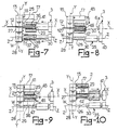
- a holder provided on the case 41 close to the opening 44 to hold a header 25, 26 as the left-over disk 46 is cut off (see Figures 8 and 9).
- the inventive method comprises a preliminary step of providing on the press 1 two tubular headers, namely a first header 25 and a second header 26 to which respective extrusion dies 29 and 30 are mounted. Further, the headers 25, 26 are driven in a guided fashion along a first direction Y-Y perpendicular to the extrusion axis X-X by the pusher means 32.
- FIG. 3 shows schematically the press 1 at the end of an extrusion course with the slide 28 associated with the fixture 15 by the latching means 31, and the respective second header 26 in the operating position, enclosed in a jacket 36 of residual brass.
- the hydraulic unit 3 is deactivated and the case 41 moved rearward from the second header 26.
- the slide 27 for the first header 25 locates on the lower bracket 21 of the elevator device 19, with the carriage at its bottom position.
- a billet 2 to be extruded is loaded, moreover, on the shelf 17 by means of a conventional billet-loading device.
- the billet 2 is first loaded into the cavity 42 of the case 41 by moving the fixture 15 along the first direction Y-Y until the billet 2 is brought into alignment with the cavity 42 (see Figure 4).
- a step is initiated wherein the billet 2 is inserted into the cavity 42 through the opening 43 by operating the pusher 18; simultaneously therewith, the motive means 24 is operated to drive the carriage of the elevator device 19 up toward its top position along the second direction W-W.
- the tenon 33 is drawn out of the groove 34 in the slide 28 and cause to successively engage in the groove 34 in the slide 27 for the first header 25, presently in the inoperative position.
- the method of this invention comprises a subsequent step of positioning the first header 25 to its operative position t for extrusion by operating the pusher means 32, and the second header 26 to its inoperative position alongside the axis X-X by moving the carriage of the elevator device 19 down to its bottom position; at the same time, the pusher 18 is retracted toward the fixture 15 (see Figure 6).
- the billet 2 is then backward extruded (see Figure 7) through the die 29 on the first header 25, to form a brass bar 12, by operating the primary assembly 4 in the hydraulic unit 3, such that the end 6a will abut against the opening 43 of the cavity 42, and then pushing the case 41 toward the slide 27 for the first header 25.
- the extruded bar 12 advances through the interior of the first tubular header 25, move past a recess suitably formed in the slide 27 and then penetrate the passageway 11. Beyond the plate 10, the brass bar 12 is picked up on completion of the extrusion process and then taken away from the press 1 by a conventional arrangement, not shown.
- the hydraulic cylinder 40 is operated and the crusher ring 37 driven forward while initially fitted over the die 30 and then the second header 26 to free the latter of the jacket 36 by crushing the same.
- the jacket 36 will stick to the die 29, excepting for the brass residue 46, thereby it envelopes the first header 25, albeit not contacting it, and the case 41 is driven toward the slide 27 until said residue or left-over 46 (see Figure 8) is caused to protrude out of the opening 44, to be then cut across the die 29 by the shears 45 (see Figure 9).
- the sleeve 38 and crusher ring 37 are slid off the header by releasing the pressure in the hydraulic cylinder 40.
- the case 41 is also moved rearward from the first header 25 and a new billet 2 is loaded onto the shelf 17, thus bringing the extrusion course on the press 1 to an end under a similar condition to that described in connection with Figure 3, but with the positions of the headers 25 and 26 reversed; according to the invention, a further step is then provided wherein the first header 25 is brought back to the inoperative position to clear it of the jacket 36, and the second header 26 to the operative position to extrude the billet 2 using the same procedure as previously described.
- the method of this invention has shown capable of speeding up the brass billet extrusion course considerably; in fact, by carrying out the billet extrusion operation proper by means of one header simultaneously with the residual brass jacket crushing operation on the other header, the downtime is greatly reduced in an extrusion course.
- Particularly advantageous has shown to be the provision of dies affixed to respective tubular headers, to thus allow the die on one header in the inoperative position to cool while the extrusion step is being carried out with the other header.
- the die affixed to the header the residual brass jacket adhering on the die itself would locate around the header, thereby it can be easily and quickly crushed after the case has been slid off.
- a further advantage afforded by the invention is that the movements of the horizontal extrusion press are simplified, particularly as relates to driving the slide-mounted header/die assemblies, while the billets can be readily loaded into the case and good access ensured to every components of the press.
Landscapes
- Engineering & Computer Science (AREA)
- Mechanical Engineering (AREA)
- Extrusion Of Metal (AREA)
Applications Claiming Priority (2)
| Application Number | Priority Date | Filing Date | Title |
|---|---|---|---|
| IT1921588 | 1988-01-26 | ||
| IT19215/88A IT1219686B (it) | 1988-01-26 | 1988-01-26 | Metodo per accelerare l'estrusione inversa di billette e simili di ottone e pressa per la sua attuazione |
Publications (2)
| Publication Number | Publication Date |
|---|---|
| EP0326008A2 true EP0326008A2 (fr) | 1989-08-02 |
| EP0326008A3 EP0326008A3 (fr) | 1990-10-03 |
Family
ID=11155865
Family Applications (1)
| Application Number | Title | Priority Date | Filing Date |
|---|---|---|---|
| EP19890100817 Ceased EP0326008A3 (fr) | 1988-01-26 | 1989-01-18 | Procédé relatif à la vitesse d'extrusion dans l'extrusion inversée des billettes en laiton et analogues, et appareil à cet effet |
Country Status (2)
| Country | Link |
|---|---|
| EP (1) | EP0326008A3 (fr) |
| IT (1) | IT1219686B (fr) |
Cited By (3)
| Publication number | Priority date | Publication date | Assignee | Title |
|---|---|---|---|---|
| CN110293227A (zh) * | 2019-07-11 | 2019-10-01 | 中国航发北京航空材料研究院 | 一种带包套的粉末高温合金锭坯的反挤压制备方法及模具 |
| CN112620374A (zh) * | 2020-12-23 | 2021-04-09 | 邱元山 | 一种短行程反向铜及铜合金挤压机 |
| CN116900074A (zh) * | 2023-09-13 | 2023-10-20 | 江阴鑫焱合金铜材有限公司 | 一种铍青铜合金反向挤压工艺 |
Family Cites Families (4)
| Publication number | Priority date | Publication date | Assignee | Title |
|---|---|---|---|---|
| GB897040A (en) * | 1959-06-26 | 1962-05-23 | Hydraulik Gmbh | An extrusion press having a die changing device |
| US3182478A (en) * | 1962-07-09 | 1965-05-11 | Kobe Steel Ltd | Hydraulic metal extruding machine |
| FR2148704A5 (en) * | 1971-07-30 | 1973-03-23 | Trefimetaux | Press piece - for indirect extrusion press |
| JPS56165516A (en) * | 1980-05-26 | 1981-12-19 | Sumitomo Light Metal Ind Ltd | Method of indirect extrusion for metal |
-
1988
- 1988-01-26 IT IT19215/88A patent/IT1219686B/it active
-
1989
- 1989-01-18 EP EP19890100817 patent/EP0326008A3/fr not_active Ceased
Cited By (3)
| Publication number | Priority date | Publication date | Assignee | Title |
|---|---|---|---|---|
| CN110293227A (zh) * | 2019-07-11 | 2019-10-01 | 中国航发北京航空材料研究院 | 一种带包套的粉末高温合金锭坯的反挤压制备方法及模具 |
| CN112620374A (zh) * | 2020-12-23 | 2021-04-09 | 邱元山 | 一种短行程反向铜及铜合金挤压机 |
| CN116900074A (zh) * | 2023-09-13 | 2023-10-20 | 江阴鑫焱合金铜材有限公司 | 一种铍青铜合金反向挤压工艺 |
Also Published As
| Publication number | Publication date |
|---|---|
| IT1219686B (it) | 1990-05-24 |
| IT8819215A0 (it) | 1988-01-26 |
| EP0326008A3 (fr) | 1990-10-03 |
Similar Documents
| Publication | Publication Date | Title |
|---|---|---|
| US1317238A (en) | Machine for extruding metal. | |
| US3528275A (en) | Method and apparatus for extruding hollow articles | |
| US3530702A (en) | Extruding method and apparatus and parts therefor | |
| EP0042260B1 (fr) | Presse de filage inverse | |
| US10124383B2 (en) | Extrusion method for extruded material | |
| EP0326008A2 (fr) | Procédé relatif à la vitesse d'extrusion dans l'extrusion inversée des billettes en laiton et analogues, et appareil à cet effet | |
| CA2196372C (fr) | Procede et appareil permettant d'extruder une section d'une billette | |
| US3738144A (en) | Inverse drawing presses | |
| US4475372A (en) | Method and means for removing a die, sealing member and residual metal from an indirect extrusion press | |
| WO1988010161A1 (fr) | Couteau de cisaillement perfectionne pour procede d'extrusion d'aluminium | |
| WO1981003441A1 (fr) | Procede indirect d'extrusion d'un metal | |
| US2963151A (en) | Die changing apparatus for metal extrusion press | |
| US3879972A (en) | Method and apparatus for removing a plug | |
| US6305207B1 (en) | Removing shell and press residue from a metal-extruding ram disk or die | |
| JPH05261429A (ja) | 間接押出プレスのダイス・製品分離方法および装置 | |
| US3653247A (en) | Extrusion press | |
| US3369385A (en) | Metal extrusion apparatus | |
| EP0493535B1 (fr) | Appareil et methode pour prepoinconner les billettes | |
| US4570473A (en) | Extrusion press | |
| US3256729A (en) | Method and apparatus for extrusion with mutiple containers | |
| US3364719A (en) | Metal extrusion press | |
| US3827273A (en) | Shearing device for unextruded butts in an indirect metal extrusion machine | |
| US5657661A (en) | Working method for loading an extrusion billet and metal extrusion press | |
| JP3331891B2 (ja) | 複動型押出プレスを用いた押出成形方法およびその装置 | |
| GB2089704A (en) | Indirect extrusion press with billet piercing |
Legal Events
| Date | Code | Title | Description |
|---|---|---|---|
| PUAI | Public reference made under article 153(3) epc to a published international application that has entered the european phase |
Free format text: ORIGINAL CODE: 0009012 |
|
| AK | Designated contracting states |
Kind code of ref document: A2 Designated state(s): AT BE CH DE ES FR GB GR IT LI LU NL SE |
|
| PUAL | Search report despatched |
Free format text: ORIGINAL CODE: 0009013 |
|
| AK | Designated contracting states |
Kind code of ref document: A3 Designated state(s): AT BE CH DE ES FR GB GR IT LI LU NL SE |
|
| 17P | Request for examination filed |
Effective date: 19900929 |
|
| RAP1 | Party data changed (applicant data changed or rights of an application transferred) |
Owner name: INNSE INNOCENTI ENGINEERING S.P.A. |
|
| 17Q | First examination report despatched |
Effective date: 19920729 |
|
| STAA | Information on the status of an ep patent application or granted ep patent |
Free format text: STATUS: THE APPLICATION HAS BEEN REFUSED |
|
| 18R | Application refused |
Effective date: 19940213 |