EP0326022B1 - Dispositif de dosage - Google Patents
Dispositif de dosage Download PDFInfo
- Publication number
- EP0326022B1 EP0326022B1 EP89100884A EP89100884A EP0326022B1 EP 0326022 B1 EP0326022 B1 EP 0326022B1 EP 89100884 A EP89100884 A EP 89100884A EP 89100884 A EP89100884 A EP 89100884A EP 0326022 B1 EP0326022 B1 EP 0326022B1
- Authority
- EP
- European Patent Office
- Prior art keywords
- threaded sleeve
- dispenser according
- actuating button
- piston
- stop
- Prior art date
- Legal status (The legal status is an assumption and is not a legal conclusion. Google has not performed a legal analysis and makes no representation as to the accuracy of the status listed.)
- Expired - Lifetime
Links
- 239000011521 glass Substances 0.000 claims description 21
- 230000001681 protective effect Effects 0.000 claims description 7
- 238000011156 evaluation Methods 0.000 claims description 5
- 210000002445 nipple Anatomy 0.000 claims description 2
- 239000012530 fluid Substances 0.000 claims 1
- 239000007788 liquid Substances 0.000 description 10
- 238000000034 method Methods 0.000 description 3
- 239000011324 bead Substances 0.000 description 2
- 238000004140 cleaning Methods 0.000 description 2
- 239000002184 metal Substances 0.000 description 2
- 239000004033 plastic Substances 0.000 description 2
- 239000004810 polytetrafluoroethylene Substances 0.000 description 2
- 229920001343 polytetrafluoroethylene Polymers 0.000 description 2
- 238000003825 pressing Methods 0.000 description 2
- 229910000831 Steel Inorganic materials 0.000 description 1
- 206010000496 acne Diseases 0.000 description 1
- 238000013459 approach Methods 0.000 description 1
- 230000004888 barrier function Effects 0.000 description 1
- 239000000919 ceramic Substances 0.000 description 1
- 238000012937 correction Methods 0.000 description 1
- 230000000994 depressogenic effect Effects 0.000 description 1
- 238000001514 detection method Methods 0.000 description 1
- 239000013013 elastic material Substances 0.000 description 1
- 125000000524 functional group Chemical group 0.000 description 1
- 230000005484 gravity Effects 0.000 description 1
- 230000001771 impaired effect Effects 0.000 description 1
- 239000000463 material Substances 0.000 description 1
- 239000010979 ruby Substances 0.000 description 1
- 229910001750 ruby Inorganic materials 0.000 description 1
- 239000011343 solid material Substances 0.000 description 1
- 239000010959 steel Substances 0.000 description 1
- 230000001954 sterilising effect Effects 0.000 description 1
- 238000004659 sterilization and disinfection Methods 0.000 description 1
- 238000004448 titration Methods 0.000 description 1
- 238000012549 training Methods 0.000 description 1
Images

Classifications
-
- B—PERFORMING OPERATIONS; TRANSPORTING
- B01—PHYSICAL OR CHEMICAL PROCESSES OR APPARATUS IN GENERAL
- B01L—CHEMICAL OR PHYSICAL LABORATORY APPARATUS FOR GENERAL USE
- B01L3/00—Containers or dishes for laboratory use, e.g. laboratory glassware; Droppers
- B01L3/02—Burettes; Pipettes
- B01L3/0289—Apparatus for withdrawing or distributing predetermined quantities of fluid
- B01L3/0293—Apparatus for withdrawing or distributing predetermined quantities of fluid for liquids
-
- G—PHYSICS
- G01—MEASURING; TESTING
- G01F—MEASURING VOLUME, VOLUME FLOW, MASS FLOW OR LIQUID LEVEL; METERING BY VOLUME
- G01F11/00—Apparatus requiring external operation adapted at each repeated and identical operation to measure and separate a predetermined volume of fluid or fluent solid material from a supply or container, without regard to weight, and to deliver it
- G01F11/02—Apparatus requiring external operation adapted at each repeated and identical operation to measure and separate a predetermined volume of fluid or fluent solid material from a supply or container, without regard to weight, and to deliver it with measuring chambers which expand or contract during measurement
- G01F11/021—Apparatus requiring external operation adapted at each repeated and identical operation to measure and separate a predetermined volume of fluid or fluent solid material from a supply or container, without regard to weight, and to deliver it with measuring chambers which expand or contract during measurement of the piston type
- G01F11/023—Apparatus requiring external operation adapted at each repeated and identical operation to measure and separate a predetermined volume of fluid or fluent solid material from a supply or container, without regard to weight, and to deliver it with measuring chambers which expand or contract during measurement of the piston type with provision for varying the stroke of the piston
Definitions
- Such dispensers are used both for precise dosing of liquid media and for titration. These devices are designed for dosing volumes in the microliter range up to the liter range.
- Metering devices of the type in question are used in particular to dispense a constant, predetermined amount of liquid several times in succession.
- the piston stroke and thus the volume to be dispensed with each dosage are set to a certain height or quantity, for example by the stroke limitation being achieved by two stops, namely a fixed and a variable stop.
- the stroke of the piston is also limited and thus adjusted.
- Such a metering device is described, for example, in EU-A-831 01699.3.
- the adjustable stop can be rotated in the circumferential direction of this known metering device in order to change the stroke limitation, while the fixed counterstop is designed as a step gauge.
- the stroke limit can be changed by turning the adjustable stop.
- the piston slide metering pump, the stop system, if any, for limiting the stroke of the piston, and the measuring system, if any are either housed in a housing or are designed such that some of the elements mentioned are arranged outside the housing for the device.
- the cylinder of the dispenser according to the invention is held liquid-tight on the valve head or valve block, which is known per se and contains an intake valve and a drain valve.
- the dispenser according to the invention is characterized, inter alia, by the fact that the actuating button is connected to a threaded sleeve which is concentric with the cylinder and rotates around the outside and is both rotatable and axially movable such that the actuating button can be freely rotated with respect to the threaded sleeve, but in the axial direction is fixed.
- the actuating button can be connected to the threaded sleeve with the aid of a connecting element in a force-locking or positive manner and therefore in a rotationally fixed manner.
- the latter non-rotatable connection is, however, releasable.
- the threaded sleeve expediently extends over the entire height of the cylinder and advantageously in the form of an extension described below.
- the threaded sleeve is equipped on its outer jacket with an external thread, which expediently extends over almost the entire height of the threaded sleeve.
- the adjustable stop of the dispenser according to the invention is a stop nut which runs concentrically to the threaded sleeve, engages around the latter (its axial height is 1/10 to 1/3 of the length of the area of the cylinder protruding from the valve head) and on the Inner surface of its inner bore has an internal thread which is in engagement with the external thread on the threaded sleeve.
- This stop nut is rotatably and rotationally guided.
- the stop nut is displaced in the axial direction by turning the threaded sleeve with the aid of the actuating button that can be connected in a rotationally fixed manner via a connecting element.
- the threaded sleeve and thus also the stop nut is moved upwards, until the stop nut comes to a stop against a counter-stop attached to the upper end of the dispenser according to the invention.
- the lifting height is determined by the position of the stop nut in relation to the threaded sleeve. The further down the stop nut is on the threaded sleeve, the greater the stroke and thus the volume of the liquid to be dispensed, which is drawn in by means of the piston.
- the external thread of the threaded sleeve preferably has multiple threads in order to be able to finely adjust the height of the stop nut with respect to the threaded sleeve.
- the thread mentioned can be a round thread or a trapezoidal thread.
- the thread is expediently designed such that five turns are required to move the stop nut from its lower position to its upper position.
- the rotationally fixed guide of the stop nut can be of a conventional type, for example a projection which is guided in an axial longitudinal rail or longitudinal groove.
- the dispenser according to the invention is equipped with a measuring system which indicates the respective position of the stop nut.
- a measuring system is expediently used, which generates, registers and processes electronic impulses when the piston (and thus also the threaded sleeve and the stop nut) is moved.
- This can be, for example, an analog measuring system, for example a capacitive measuring system.
- it is preferably a digital measuring system which, after evaluation in an electronic evaluation circuit, displays the determined result on a digital display device.
- This measuring system preferably has a glass scale support equipped with a glass scale, which is arranged parallel to the cylinder and to the threaded sleeve and to the side thereof and extends through an opening which is recessed in the stop nut, preferably in a lateral extension thereof, and thus ensures that the stop nut is twisted.
- the glass scale is scanned with a sensor head described in more detail below.
- the measuring system is expediently microprocessor-controlled and allows the dispensed volume to be calibrated using an analytical balance. This makes it possible to adjust the number of measured pulses to the actually dispensed volume by means of a correction factor, which is taken into account, which ensures that all mechanical deviations in the piston and cylinder diameter are eliminated.
- this measuring system enables a continuous and precise stop adjustment and thus an exact adjustment of the dispensed volume.
- this glass scale support of the measuring system simultaneously ensures that the stop nut is not also rotated when the threaded sleeve is rotated, but is held in a rotationally fixed manner.
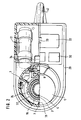
- a particularly ergonomically designed and easy to use embodiment of the dispenser according to the invention is characterized in that the cylinder and the piston (together form a piston slide metering pump), the stop system with the associated parts and the measuring system are arranged in a housing which is arranged approximately vertically and has a cylindrical shape.
- the valve head which is of a conventional type and contains an intake valve and a drain valve, is located in the lower region of the housing and can be fitted or screwed onto a storage vessel.
- the stop system with e.g. stop nut, threaded sleeve and counter stop, as well as with the measuring system are housed; further details are described below.
- the functional parts which are necessary for the actual dispensing process, for limiting the stroke height of the piston and for registering or measuring the piston height and thus the stroke volume, are thus combined into a functional group, which is housed in the vertical cylindrical (hollow cylindrical) housing part are.
- this lateral spout arm has the shape of a flat, lying cuboid, which is inclined slightly downwards from the horizontal.
- the term "lying" is intended to express that one of the large side surfaces of the cuboid represents the lower limit of the grommet arm. The other of the large side areas represents the upper limit.
- the housing is preferably constructed from segments that can be assembled.
- the lower segment engages around the valve head, extends on the side facing away from the nozzle arm to the lower region of the cylinder and also includes the lower section of the nozzle arm and the protective sleeve of the ejection cannula.
- the third segment of the housing constitutes the upper cover of the rectangular sleeve arm and extends from the lower sleeve arm end of the upper segment to the end of the sleeve arm and beyond, so that the third segment also forms part of the protective sleeve for the ejection cannula.
- Various recesses are provided in this third segment, which are used to hold a display or a display device and to hold operating buttons.
- the dispenser 1 according to the invention shown in FIG. 1 has a valve head 3 which can be placed on a storage container, for example a bottle (not shown).
- the valve head 3 is known per se and contains an intake valve and a drain valve. These valves are expediently gravity-loaded ruby ball valves.
- the valve head is usually made of PTFE.
- a horizontal connection piece 34 is arranged laterally in the upper region of the valve head, from which the ejection cannula 33 is led out.
- a cylinder 2 made of glass is inserted in a liquid-tight manner.
- piston 4 which, in the fully inserted state, projects beyond the free end of the cylinder 2.
- the core of the piston consists of a tube made of glass, ceramic or metal, which is open on both sides, the tube being encased in a one-piece PTFE jacket made of solid material.
- the actuation button 5 is approximately cylindrical. Its outer diameter tapers in the lower region to form a circular shoulder 36 which, when the piston 4 is pressed down, comes into abutment against a stop bead attached to the upper end of the housing 29, shortly before or when the piston 4 reaches its bottom dead center.
- the shoulder 36 and the stop bead are designed in such a way that as little friction as possible arises when the actuating button 5 is turned.
- the actuating button 5 carries on the valve head side an apron 16 concentric with the piston 4 and circumferentially spaced around the piston 4, on the outer lateral surface of which an axially extending toothing 37 is arranged.
- the threaded sleeve 8 is equipped on its outer jacket with an external thread 10 which extends almost to both ends of the threaded sleeve. Following the upper region of the external thread 10, a toothing 38 corresponding to the toothing 37 on the apron 16 is attached to the outer jacket of the threaded sleeve 8 at the upper end.
- the outer diameter of the threaded sleeve 8 tapers upward following the teeth 38; it then extends upwards in the form of a cylindrical extension 18 which projects into an annular groove 23 located in the actuating button 5.
- the actuating button 5 and the threaded sleeve 8 are designed so that the apron 16 and the end of the threaded sleeve 8 carrying the teeth 38 come as close as possible.
- gear cylinder 9 is provided, which is arranged axially parallel to the piston 4 and laterally from the actuating button 5 or the threaded sleeve 8 such that it can be pressed simultaneously against both the teeth 37 on the apron 16 and against the teeth 38 at the upper end of the threaded sleeve 8.
- the toothing 37 thus meshes with the toothing 38 via the gear cylinder 9 when the cylinder 9 is pressed.
- the gear cylinder 9 is rotatably supported on its two end faces by a fork 19 which is fastened to the housing 29 via a bracket 20.
- the bracket 20 is an elastic material which is fastened to the housing 29 at the end opposite the fork 19, as a result of which the gear cylinder 9 is spring-mounted.
- gear cylinder 9 can also be replaced by a connecting element ensuring a frictional connection between the actuating button 5 and the threaded sleeve 8, for example a friction wheel. In this case, perforation is not absolutely necessary.
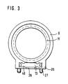
- the height of the stop nut 6 can be adjusted extremely finely with respect to the threaded sleeve 8.
- an O-ring 39 which extends radially around the outside, is attached to the lower end of the threaded sleeve 8.
- the upper area of the stop nut 6 has no internal thread, but rather forms an annular cylinder which does not touch the threaded sleeve 8 and whose upper edge surface touches the counter stop 7 when it is raised.
- the cylindrical stop nut 6 has a lateral extension 26 with an axial opening 13 with a substantially rectangular cross section. There are two nipples 27 on the side of the attachment 26, with the aid of which a sensor head 14 can be attached to it.
- the sensor head 14 is electrically connected to control elements 32 and a digital display device 22 via a ribbon cable 41.
- the display device 22 and the operating elements 32 are mounted on the top of a grommet arm 30, which has the shape of a flat, lying cuboid, which is slightly inclined with respect to the horizontal. Batteries 31 are also accommodated in this grommet arm 30.
- the ejection cannula 33 which also extends in the lateral spout arm 30, runs outside the spout arm in a rigid protective sleeve 42.
- the housing 29 of the dispenser according to the invention consists of three housing segments 29a, 29b, 29c.
- the lower housing segment 29a surrounds the valve head 3 and projects beyond this valve head 3 on the side facing away from the spout arm 30.
- the lower area of the sleeve arm is on the sleeve arm side 30 and the protective sleeve 42 are molded onto the area surrounding the valve head 3.
- the upper housing segment 29b encloses the upper region of the cylinder 2, the glass scale support 12 and the gear cylinder 9.
- the counter-stop 7 is molded on the inside of this housing segment 29b in the upper region.
- the housing segment 29c thus extends from the lower arm-side end of the housing segment 29b to the end face of the flat cuboid and beyond, so that the upper region of the region of the protective sleeve 42 which adjoins the tubular arm and extends down to approximately the bend downward from this housing segment 29c is formed.
- the housing can be taken apart and cleaning or sterilization work can be carried out conveniently. So you can completely remove the operating button 5 together with the piston 4 from the cylinder 2. Due to the snap-type connection between the apron 16 via the dome-like projections 25 with the cylindrical extension 18 of the threaded sleeve 8, the actuating button 5 can also be separated from the threaded sleeve 8. The upper housing segment 29b and also the housing segment 29c can then be removed, so that the valve head 3 can be removed from the lower housing segment 29a.
Landscapes
- Chemical & Material Sciences (AREA)
- Physics & Mathematics (AREA)
- Fluid Mechanics (AREA)
- General Physics & Mathematics (AREA)
- Analytical Chemistry (AREA)
- Health & Medical Sciences (AREA)
- Clinical Laboratory Science (AREA)
- Chemical Kinetics & Catalysis (AREA)
- Containers And Packaging Bodies Having A Special Means To Remove Contents (AREA)
- Closures For Containers (AREA)
- Reciprocating Pumps (AREA)
Claims (15)
- Distributeur ou appareil de dosage pour doser exactement des produits liquides, provenant d'un récipient de stockage, dans un collecteur comportant un cylindre (2), qui est maintenu par une tête de soupape (3) pouvant être reliée au récipient de stockage et comportant une soupape d'aspiration et une soupape de sortie, un piston (4) pouvant se déplacer, guidé dans le cylindre (2), qui est raccordé de façon fixe à un bouton d'actionnement (5) à son extrémité opposée à la tête de soupape (3), et une butée (6) réglable pour modifier la limite de course du piston, ainsi qu'une contre-butée (7) disposée dans la zone supérieure du distributeur (1) et agissant avec la précédente,
caractérisé par
- une douille filetée (8), mobile axialement et en rotation,
qui est concentrique avec le cylindre (2) et entoure ce dernier extérieurement,
qui est reliée de façon fixe avec le bouton d'actionnement (5) dans la direction axiale, mais étant entendu que le bouton d'actionnement (5) peut toutefois être tourne librement par rapport à cette douille filetée (8),
qui est réalisée avec un filetage extérieur (10) sur sa surface externe, et
qui porte la butée réglable (6), qui est un écrou de butée (6) fixe en rotation et concentrique avec la douille filetée (8), cet écrou présentant, sur la surface intérieure de son alésage intérieur, un filetage intérieur (11), qui fait prise sur l'alésage extérieur (10) de la douille filetée (8),
- et par un organe de liaison (9), qui, lors de l'actionnement, relie, sans possibilité de rotation, le bouton d'actionnement (5) avec la douille filetée (8), de telle façon que, si on tourne le bouton d'actionnement (5), et avec lui également la douille filetée (8), on fait déplacer l'écrou fileté (6) suivant la direction axiale. - Distributeur suivant la revendication 1, caractérisé par un système de mesure indiquant chaque position correspondante de l'écrou de butée (6).
- Distributeur suivant la revendication 2, caractérisé en ce que le système de mesure fournit, lors du déplacement du piston, des impulsions électroniques et les enregistre, et, après exploitation dans un circuit d'interprétation, les reporte sur un dispositif formant écran (22), en particulier, un écran numérique.
- Distributeur suivant la revendication 3, caractérisé en ce que le système de mesure présente un support d'échelle de mesure (12) comportant une échelle de mesure en verre, support qui est disposé sur le côté et parallèlement au cylindre (2) et à la douille filetée (8), et qui passe au travers d'une ouverture traversante (13) dans l'écrou de butée (6), et en ce que, sur l'écrou de butée (6), est fixée une tête de capteur (14) pour lire, sans contact, l'échelle de mesure en verre située sur le support (12) de l'échelle de mesure en verre.
- Distributeur suivant la revendication 4, caractérisé en ce que l'ouverture (13) est disposée dans un prolongement latéral (26) de l'écrou de butée (6) et présente essentiellement une section rectangulaire, étant entendu que l'un des grands côtés de la section rectangulaire est disposée tangentiellement au filetage intérieur (11).
- Distributeur suivant la revendication 5, caractérise en ce que, sur le prolongement latéral (26), est rapporté au moins un ergot (27) pour fixer la tête de capteur (14), et en ce que, dans la paroi extérieure du prolongement latéral (26), est dispose une fenêtre (28) allant vers l'ouverture (13).
- Distributeur suivant l'une quelconque des revendications précédentes, caractérisé en ce qu'on peut, en particulier en repoussant un ressort agissant vers l'extérieur, appliquer radialement depuis l'extérieur l'organe de raccordement (9) aussi bien contre le bouton d'actionnement (5) qu'également contre la douille filetée (8), en réalisant une liaison à engagement géométrique ou dynamique, .
- Distributeur suivant la revendication 7, caractérisé- en ce que le bouton d'actionnement (5) présente, du côté de la tête de soupape, une bavette (16) qui entoure le piston (4) et est concentrique avec lui, qui possède, sur sa surface externe, une denture (37) disposée axialement
- en ce que la douille filetée (8), à son extrémité se terminant axialement sur la bavette (16), présente le même diamètre extérieur que la bavette (16), et présente, de même, sur sa surface externe une denture dirigée axialement, et
- en ce que l'organe de raccordement (9) est un cylindre denté (9) qui comporte une denture dirigée axialement, et dont l'axe longitudinal est parallèle à l'axe du piston (4), et qui est monté tournant autour de cet axe longitudinal. - Distributeur suivant la revendication 8, caractérisé en ce que le cylindre denté (9) est maintenu tournant sur ses deux surfaces d'extrémité, au moyen d'une fourche (19), qui est reliée à un bouton d'actionnement (21) par l'intermédiaire d'un étrier (20), mobile en direction axiale.
- Distributeur suivant l'une quelconque des revendications précédentes, caractérisé en ce que la douille filetée (8) présente, à son extrémité tournée vers le bouton d'actionnement (5), un prolongement cylindrique (18) comportant le même diamètre intérieur, mais toutefois un diamètre extérieur plus faible, prolongement qui s'engage dans une rainure annulaire (23) se trouvant dans le bouton d'actionnement (5) et qui, au moyen de ce prolongement, est relie solidairement avec la douille filetée (8) de façon à être fixe dans la direction axiale, le prolongement (18) pouvant tourner, par rapport au bouton d'actionnement (5), sans frottement, ou presque sans frottement.
- Distributeur suivant la revendication 10, caractérisé en ce que le prolongement cylindrique (18) présente une gorge circulaire radiale, en particulier une gorge en forme de V, dans laquelle pénètrent plusieurs saillies en forme de calotte (25), réparties sur la périphérie et disposées en face de la gorge (24), sur la paroi latérale de la rainure (23), soit du côté extérieur radialement, soit du côté intérieur radialement.
- Distributeur suivant l'une quelconque des revendications précédentes, caractérisé en ce que le cylindre (2), le piston (4), la butée (6), la buse filetée (8) et, le cas échéant, le système de mesure (12, 14, 15) sont disposes dans un boîtier vertical (29), de forme au moins essentiellement cylindrique, en ce que, sur le côté du boîtier (29), est rapporte un bras verseur (30), dans lequel, le cas écheant, le dispositif indicateur (30) et les organes de commande (32) sont disposés, et en ce qu'une canule éjectrice passe au travers du bras verseur et sort de ce dernier.
- Distributeur suivant la revendication 12, caractérisé en ce que le bras verseur (30) présente essentiellement la forme d'un quadrilatère plat horizontal, qui, par rapport à la normale au boîtier (29), est légèrement incliné vers la tête de soupape (3).
- Distributeur suivant la revendication 12 ou la revendication 13, caractérisé en ce que les organes d'actionnement (32) et le dispositif indicateur (30) sont disposés sur le côté du bras verseur (30) et en ce que, dans le bras verseur (30), est disposé, le cas échéant, également une source de tension (31) pour le système de mesure.
- Distributeur suivant l'une quelconque des revendications 12 à 14, caractérisé en ce que la canule éjectrice (33) sort par le côté du quadrilatère opposé au boîtier cylindrique (29) et est guidée et protégée, à l'extérieur du bras verseur (30), dans une douille de protection rigide, placée contre, qui, à son extrémité libre, du côté tourne vers la tête de soupape (3), est recourbée de façon à être dirigée parallèlement au boîtier (29).
Applications Claiming Priority (2)
| Application Number | Priority Date | Filing Date | Title |
|---|---|---|---|
| DE8800844U | 1988-01-25 | ||
| DE8800844U DE8800844U1 (de) | 1988-01-25 | 1988-01-25 | Dispenser |
Publications (2)
| Publication Number | Publication Date |
|---|---|
| EP0326022A1 EP0326022A1 (fr) | 1989-08-02 |
| EP0326022B1 true EP0326022B1 (fr) | 1993-01-13 |
Family
ID=6819926
Family Applications (1)
| Application Number | Title | Priority Date | Filing Date |
|---|---|---|---|
| EP89100884A Expired - Lifetime EP0326022B1 (fr) | 1988-01-25 | 1989-01-19 | Dispositif de dosage |
Country Status (3)
| Country | Link |
|---|---|
| US (1) | US4995532A (fr) |
| EP (1) | EP0326022B1 (fr) |
| DE (2) | DE8800844U1 (fr) |
Families Citing this family (11)
| Publication number | Priority date | Publication date | Assignee | Title |
|---|---|---|---|---|
| DE3838741A1 (de) * | 1988-11-15 | 1990-05-17 | Graf & Co Gmbh Walter | Volumenmessgeraet mit hubkolben zur abgabe definierter fluessigkeitsmengen |
| FI87740C (fi) * | 1990-05-04 | 1994-04-08 | Biohit Oy | Pipett |
| US5624059A (en) * | 1995-04-05 | 1997-04-29 | Axys Environmental Systems Ltd. | Device for dispensing corrosive liquids accurately and without contamination |
| SG54522A1 (en) * | 1996-06-24 | 1998-11-16 | Industrieplanung Theodor Fesse | Liquid dispenser supplying and dosing cylinder device in particular for liquid dispenser and method for manufacturing a liquid dispenser |
| ATE480330T1 (de) * | 2001-10-16 | 2010-09-15 | Matrix Technologies Corp | Hand-pipettiervorrichtung |
| US20060027033A1 (en) * | 2002-10-16 | 2006-02-09 | Richard Cote | Hand-held pipette employing voice recognition control |
| US7284454B2 (en) * | 2004-05-27 | 2007-10-23 | Matrix Technologies Corporation | Hand held pipette |
| US8597593B2 (en) * | 2006-12-07 | 2013-12-03 | Brand Gmbh + Co Kg | Bottle top dispenser for handling liquids |
| US8142738B2 (en) | 2006-12-07 | 2012-03-27 | Brand Gmbh + Co Kg | Bottle top dispenser for handling liquids |
| DE202007017095U1 (de) * | 2006-12-07 | 2008-04-17 | Brand Gmbh + Co Kg | Flaschenaufsatzgerät zur Handhabung von Flüssigkeiten |
| CN115254224B (zh) * | 2022-07-29 | 2024-03-19 | 广州国睿科学仪器有限公司 | 一种用于瓶口移液器的抽取组件 |
Family Cites Families (16)
| Publication number | Priority date | Publication date | Assignee | Title |
|---|---|---|---|---|
| DE253675C (fr) * | ||||
| US3283727A (en) * | 1964-11-02 | 1966-11-08 | Microchemical Specialties Co | Liquid dispenser with automatic air purge |
| US3729022A (en) * | 1971-01-04 | 1973-04-24 | Oxford Lab | Disassembleable valve and liquid dispensing device |
| US3805998A (en) * | 1972-11-17 | 1974-04-23 | M Croslin | Dispensing pipette |
| JPS5892Y2 (ja) * | 1976-02-19 | 1983-01-05 | 株式会社ニチリョ− | 液体分注器 |
| FR2362371A1 (fr) * | 1976-08-18 | 1978-03-17 | Marteau Autry Eric | Dispositif distributeur de volumes reglables de liquide |
| US4096751A (en) * | 1977-06-15 | 1978-06-27 | Oxford Laboratories Inc. | Hand-held micropipettor with fluid transfer volume adjustment mechanism |
| US4273257A (en) * | 1977-07-18 | 1981-06-16 | Sherwood Medical Industries Inc. | Jar mounted pipettor |
| JPS601383Y2 (ja) * | 1979-04-19 | 1985-01-16 | 株式会社ニチリヨー | デイスペンサ |
| DE3031830C2 (de) * | 1980-08-23 | 1983-02-17 | Witeg-Glasgeräte Helmut Antlinger KG, 6980 Wertheim | Flaschendispenser |
| DE3143600A1 (de) * | 1981-11-03 | 1983-05-11 | Nichiryo Co., Ltd., Tokyo | Fluessigkeitsausgabegeraet |
| DE3208436C2 (de) * | 1982-02-22 | 1985-09-26 | Glasgerätebau Hirschmann, 7101 Eberstadt | Flaschendispenser |
| US4671123A (en) * | 1984-02-16 | 1987-06-09 | Rainin Instrument Co., Inc. | Methods and apparatus for pipetting and/or titrating liquids using a hand held self-contained automated pipette |
| DE3516596A1 (de) * | 1985-04-02 | 1986-10-02 | Walter Graf U. Co Gmbh & Co, 6980 Wertheim | Praezisionsdosiergeraet mit digitaler anzeigevorrichtung |
| GB2174459B (en) * | 1985-05-04 | 1988-05-25 | Jencons | Liquid dispensing means |
| GB8614850D0 (en) * | 1986-06-18 | 1986-07-23 | Jencons Scient Ltd | Liquid dispensers |
-
1988
- 1988-01-25 DE DE8800844U patent/DE8800844U1/de not_active Expired
-
1989
- 1989-01-19 DE DE8989100884T patent/DE58903246D1/de not_active Expired - Fee Related
- 1989-01-19 EP EP89100884A patent/EP0326022B1/fr not_active Expired - Lifetime
- 1989-01-24 US US07/300,978 patent/US4995532A/en not_active Expired - Fee Related
Also Published As
| Publication number | Publication date |
|---|---|
| US4995532A (en) | 1991-02-26 |
| DE58903246D1 (en) | 1993-02-25 |
| EP0326022A1 (fr) | 1989-08-02 |
| DE8800844U1 (de) | 1988-06-23 |
Similar Documents
| Publication | Publication Date | Title |
|---|---|---|
| DE3840000C2 (de) | Injektionsgerät | |
| DE2343687C3 (de) | Flaschendispenser zur Abgabe von Flüssigkeit | |
| EP0649678B1 (fr) | Pipette à piston | |
| DE2830014C3 (de) | Pipettiergerät | |
| DE2857423C2 (fr) | ||
| DE3208436C2 (de) | Flaschendispenser | |
| DE2342063C3 (de) | Mit der Hand zu haltende Pipette | |
| EP0326022B1 (fr) | Dispositif de dosage | |
| DE2702539A1 (de) | Vorrichtung zur abgabe von fluessigkeit in genau vorherbestimmten mengen | |
| DE7603096U1 (de) | Vorrichtung zur dosierten Abgabe viskoser Massen | |
| DE3131650A1 (de) | "verfahren und vorrichtung zum abgeben von viskosen konzentraten veraenderlicher viskositaet in genau dosierbaren mengen von variablem volumen" | |
| DE102014109345A1 (de) | Pipette zum Betätigen einer Spritze | |
| DE2309547C3 (de) | Gerät zum Füllen und Entleeren eines Flüssigkeitsbehälters, z.B. einer Pipette | |
| CH617362A5 (fr) | ||
| DE69116355T2 (de) | Prozedur zum verriegeln der verstellvorrichtung einer pipette, und pipette | |
| DE8208367U1 (de) | Dosiergeraet zur abgabe von fluessigkeit aus einem behaelter | |
| DE19915771C1 (de) | System zum Aufnehmen und Abgeben von Fluidvolumina | |
| DE3031830C2 (de) | Flaschendispenser | |
| DE3534550A1 (de) | Praezisionsdosiergeraet mit digitaler anzeigevorrichtung | |
| DE2825015A1 (de) | Fluessigkeitsuebertragungsgeraet | |
| DE3221438A1 (de) | Vorrichtung zum entnehmen einer bestimmten fluessigkeitsmenge aus einem behaelter | |
| DE3802068A1 (de) | Dispenser | |
| DE3516596A1 (de) | Praezisionsdosiergeraet mit digitaler anzeigevorrichtung | |
| DE2705655C2 (fr) | ||
| DE29705992U1 (de) | Dosierbehälter |
Legal Events
| Date | Code | Title | Description |
|---|---|---|---|
| PUAI | Public reference made under article 153(3) epc to a published international application that has entered the european phase |
Free format text: ORIGINAL CODE: 0009012 |
|
| AK | Designated contracting states |
Kind code of ref document: A1 Designated state(s): CH DE FR GB IT LI NL |
|
| 17P | Request for examination filed |
Effective date: 19900131 |
|
| 17Q | First examination report despatched |
Effective date: 19910425 |
|
| GRAA | (expected) grant |
Free format text: ORIGINAL CODE: 0009210 |
|
| AK | Designated contracting states |
Kind code of ref document: B1 Designated state(s): CH DE FR GB IT LI NL |
|
| PG25 | Lapsed in a contracting state [announced via postgrant information from national office to epo] |
Ref country code: IT Free format text: LAPSE BECAUSE OF FAILURE TO SUBMIT A TRANSLATION OF THE DESCRIPTION OR TO PAY THE FEE WITHIN THE PRE;WARNING: LAPSES OF ITALIAN PATENTS WITH EFFECTIVE DATE BEFORE 2007 MAY HAVE OCCURRED AT ANY TIME BEFORE 2007. THE CORRECT EFFECTIVE DATE MAY BE DIFFERENT FROM THE ONE RECORDED.SCRIBED TIME-LIMIT Effective date: 19930113 Ref country code: NL Effective date: 19930113 Ref country code: FR Effective date: 19930113 |
|
| PGFP | Annual fee paid to national office [announced via postgrant information from national office to epo] |
Ref country code: GB Payment date: 19930215 Year of fee payment: 5 |
|
| PGFP | Annual fee paid to national office [announced via postgrant information from national office to epo] |
Ref country code: CH Payment date: 19930224 Year of fee payment: 5 |
|
| REF | Corresponds to: |
Ref document number: 58903246 Country of ref document: DE Date of ref document: 19930225 |
|
| GBT | Gb: translation of ep patent filed (gb section 77(6)(a)/1977) |
Effective date: 19930129 |
|
| EN | Fr: translation not filed | ||
| NLV1 | Nl: lapsed or annulled due to failure to fulfill the requirements of art. 29p and 29m of the patents act | ||
| PLBE | No opposition filed within time limit |
Free format text: ORIGINAL CODE: 0009261 |
|
| STAA | Information on the status of an ep patent application or granted ep patent |
Free format text: STATUS: NO OPPOSITION FILED WITHIN TIME LIMIT |
|
| 26N | No opposition filed | ||
| PG25 | Lapsed in a contracting state [announced via postgrant information from national office to epo] |
Ref country code: GB Effective date: 19940119 |
|
| PG25 | Lapsed in a contracting state [announced via postgrant information from national office to epo] |
Ref country code: CH Effective date: 19940131 Ref country code: LI Effective date: 19940131 |
|
| GBPC | Gb: european patent ceased through non-payment of renewal fee |
Effective date: 19940119 |
|
| REG | Reference to a national code |
Ref country code: CH Ref legal event code: PL |
|
| PGFP | Annual fee paid to national office [announced via postgrant information from national office to epo] |
Ref country code: DE Payment date: 19960229 Year of fee payment: 8 |
|
| PG25 | Lapsed in a contracting state [announced via postgrant information from national office to epo] |
Ref country code: DE Effective date: 19971001 |