EP0326036A2 - Dispositif pour la fabrication de corps thermoplastiques moulés - Google Patents
Dispositif pour la fabrication de corps thermoplastiques moulés Download PDFInfo
- Publication number
- EP0326036A2 EP0326036A2 EP89100986A EP89100986A EP0326036A2 EP 0326036 A2 EP0326036 A2 EP 0326036A2 EP 89100986 A EP89100986 A EP 89100986A EP 89100986 A EP89100986 A EP 89100986A EP 0326036 A2 EP0326036 A2 EP 0326036A2
- Authority
- EP
- European Patent Office
- Prior art keywords
- scraper
- point
- loading
- mixing shaft
- outflow
- Prior art date
- Legal status (The legal status is an assumption and is not a legal conclusion. Google has not performed a legal analysis and makes no representation as to the accuracy of the status listed.)
- Withdrawn
Links
Images

Classifications
-
- B—PERFORMING OPERATIONS; TRANSPORTING
- B29—WORKING OF PLASTICS; WORKING OF SUBSTANCES IN A PLASTIC STATE IN GENERAL
- B29B—PREPARATION OR PRETREATMENT OF THE MATERIAL TO BE SHAPED; MAKING GRANULES OR PREFORMS; RECOVERY OF PLASTICS OR OTHER CONSTITUENTS OF WASTE MATERIAL CONTAINING PLASTICS
- B29B17/00—Recovery of plastics or other constituents of waste material containing plastics
-
- B—PERFORMING OPERATIONS; TRANSPORTING
- B29—WORKING OF PLASTICS; WORKING OF SUBSTANCES IN A PLASTIC STATE IN GENERAL
- B29C—SHAPING OR JOINING OF PLASTICS; SHAPING OF MATERIAL IN A PLASTIC STATE, NOT OTHERWISE PROVIDED FOR; AFTER-TREATMENT OF THE SHAPED PRODUCTS, e.g. REPAIRING
- B29C48/00—Extrusion moulding, i.e. expressing the moulding material through a die or nozzle which imparts the desired form; Apparatus therefor
- B29C48/25—Component parts, details or accessories; Auxiliary operations
- B29C48/36—Means for plasticising or homogenising the moulding material or forcing it through the nozzle or die
- B29C48/475—Means for plasticising or homogenising the moulding material or forcing it through the nozzle or die using pistons, accumulators or press rams
- B29C48/48—Two or more rams or pistons
-
- B—PERFORMING OPERATIONS; TRANSPORTING
- B29—WORKING OF PLASTICS; WORKING OF SUBSTANCES IN A PLASTIC STATE IN GENERAL
- B29C—SHAPING OR JOINING OF PLASTICS; SHAPING OF MATERIAL IN A PLASTIC STATE, NOT OTHERWISE PROVIDED FOR; AFTER-TREATMENT OF THE SHAPED PRODUCTS, e.g. REPAIRING
- B29C48/00—Extrusion moulding, i.e. expressing the moulding material through a die or nozzle which imparts the desired form; Apparatus therefor
- B29C48/25—Component parts, details or accessories; Auxiliary operations
- B29C48/36—Means for plasticising or homogenising the moulding material or forcing it through the nozzle or die
- B29C48/50—Details of extruders
- B29C48/505—Screws
- B29C48/63—Screws having sections without mixing elements or threads, i.e. having cylinder shaped sections
-
- B—PERFORMING OPERATIONS; TRANSPORTING
- B29—WORKING OF PLASTICS; WORKING OF SUBSTANCES IN A PLASTIC STATE IN GENERAL
- B29C—SHAPING OR JOINING OF PLASTICS; SHAPING OF MATERIAL IN A PLASTIC STATE, NOT OTHERWISE PROVIDED FOR; AFTER-TREATMENT OF THE SHAPED PRODUCTS, e.g. REPAIRING
- B29C48/00—Extrusion moulding, i.e. expressing the moulding material through a die or nozzle which imparts the desired form; Apparatus therefor
- B29C48/03—Extrusion moulding, i.e. expressing the moulding material through a die or nozzle which imparts the desired form; Apparatus therefor characterised by the shape of the extruded material at extrusion
-
- B—PERFORMING OPERATIONS; TRANSPORTING
- B29—WORKING OF PLASTICS; WORKING OF SUBSTANCES IN A PLASTIC STATE IN GENERAL
- B29C—SHAPING OR JOINING OF PLASTICS; SHAPING OF MATERIAL IN A PLASTIC STATE, NOT OTHERWISE PROVIDED FOR; AFTER-TREATMENT OF THE SHAPED PRODUCTS, e.g. REPAIRING
- B29C48/00—Extrusion moulding, i.e. expressing the moulding material through a die or nozzle which imparts the desired form; Apparatus therefor
- B29C48/25—Component parts, details or accessories; Auxiliary operations
- B29C48/285—Feeding the extrusion material to the extruder
- B29C48/288—Feeding the extrusion material to the extruder in solid form, e.g. powder or granules
-
- B—PERFORMING OPERATIONS; TRANSPORTING
- B29—WORKING OF PLASTICS; WORKING OF SUBSTANCES IN A PLASTIC STATE IN GENERAL
- B29C—SHAPING OR JOINING OF PLASTICS; SHAPING OF MATERIAL IN A PLASTIC STATE, NOT OTHERWISE PROVIDED FOR; AFTER-TREATMENT OF THE SHAPED PRODUCTS, e.g. REPAIRING
- B29C48/00—Extrusion moulding, i.e. expressing the moulding material through a die or nozzle which imparts the desired form; Apparatus therefor
- B29C48/25—Component parts, details or accessories; Auxiliary operations
- B29C48/285—Feeding the extrusion material to the extruder
- B29C48/29—Feeding the extrusion material to the extruder in liquid form
-
- Y—GENERAL TAGGING OF NEW TECHNOLOGICAL DEVELOPMENTS; GENERAL TAGGING OF CROSS-SECTIONAL TECHNOLOGIES SPANNING OVER SEVERAL SECTIONS OF THE IPC; TECHNICAL SUBJECTS COVERED BY FORMER USPC CROSS-REFERENCE ART COLLECTIONS [XRACs] AND DIGESTS
- Y02—TECHNOLOGIES OR APPLICATIONS FOR MITIGATION OR ADAPTATION AGAINST CLIMATE CHANGE
- Y02W—CLIMATE CHANGE MITIGATION TECHNOLOGIES RELATED TO WASTEWATER TREATMENT OR WASTE MANAGEMENT
- Y02W30/00—Technologies for solid waste management
- Y02W30/50—Reuse, recycling or recovery technologies
- Y02W30/62—Plastics recycling; Rubber recycling
Definitions
- the invention relates to a device for the production of molded articles from thermoplastic material, in particular thermoplastic waste material, comprising a cylindrical flow chamber with a material loading point in a first end section and an outflow point for thermoplastic material in a second end section, an essentially concentrically arranged within the cylindrical flow chamber a rotary drive connected mixing shaft, which defines an annular space together with the flow chamber and carries mixing elements within the annular space, heating means for heating the material contained in the flow chamber and ejection means for ejecting the thermoplastic material through the outflow point in portions.
- the mixing shaft is designed essentially over its entire length as a worm shaft, can be moved back and forth in the axial direction of the flow chamber and is provided with a check valve at its end facing the outflow opening.
- a metering chamber is formed in the area of the outflow point.
- the material is first conveyed towards the metering chamber with plasticization, the worm shaft rotating and at the same time withdrawing in the axial direction from the outflow point.
- the thermoplastic material flows into the metering chamber via the check valve.
- the check valve closes and the thermoplastic mass contained in the metering chamber is pushed out.
- the invention has for its object to provide a device of the type mentioned that it can be constructed from simple and inexpensive elements and largely avoids malfunctions.
- the annular space receives an annular piston which can be moved back and forth in its axial direction, which can be retracted behind the material loading point for refilling the flow chamber and can be advanced in the direction of the outflow point for expelling the thermoplastic material.
- an extrusion press for conveying plastic masses in which a first non-rotatable piston is arranged centrally in a cylindrical flow chamber and a likewise non-rotatable annular piston is arranged in the annular space between the first piston and the chamber jacket.
- a hydraulic linear drive is assigned to each of the two pistons.
- the first piston cooperates with a movable valve ring at its end facing the outflow of the flow chamber, which sealingly rests against the conical end of the first piston when the first piston is fed in the direction of the outflow, and when the first piston returns from the conical surface of the first Piston lifts up, but is carried along by the driving elements of the first piston under the valve opening. Heating is not provided since the mass to be pressed is obviously already offered in the plastic state.
- the same problems arise that have been dealt with in the generic state of the art as a result of the check valve there.
- a spraying machine for the continuous processing of meltable or thermoplastic materials is treated.
- a mixing and delivery shaft is arranged in a cylindrical flow chamber. This mixing and conveying shaft takes over the feed of the plasticized mass towards the outflow point.
- An organ comparable to the ring piston of the subject of the invention is not present.
- the device according to the invention is suitable for processing conventional thermoplastic raw materials in the form of granules or chips.
- the device is suitable for processing raw materials which have a considerable proportion of impurities, since the sensitive check valve is avoided. It has been shown that coarse waste material which contains infusible impurities, in particular metal parts, can also be processed with the device according to the invention. So it is z. B. possible to process yoghurt cups to which metal foil lids still adhere without disturbances to be expected.
- moldings are on the one hand those bodies which, because of their shape, are to be regarded as the end product. Molded body but are also intermediate products in strand or schnitzel form, which in turn have to be processed into functional parts.
- the mixing shaft can be designed as a screw conveyor in a first area adjacent to the material loading point and can be made essentially smooth in a second area adjoining it to the outflow point, the annular piston then directly abutting the inner peripheral surface of the flow chamber and the outer peripheral surface of the mixing shaft at least in the second area or at most with a small radial distance.
- the screw conveyor for the raw material filled in by the charging point can also take on a conveying function during its rotation, which basically serves the purpose of mixing, and convey the freshly filled raw material in the direction of the outflow point.
- the ring piston then becomes effective in the second region and pushes the filled raw material in the direction of the outflow point, the material in contact with the outflow point being thermoplasticized to such an extent that it is pushed out as a liquid to viscous mass through the outflow point.
- the mixing elements can be arranged on the mixing shaft in a third region which adjoins the second region towards the outflow point and which cannot be reached by the annular piston. In this way, any forms of mixing elements can be used which are optimized with regard to the mixing function and do not collide with the ring piston.
- the annular piston can be brought as close as possible to the screw conveyor in the first area and at the same time as close as possible to the inner peripheral surface of the flow chamber. It is thus achieved that the pushing-out action of the ring piston begins in the first area before the ring piston reaches the second area.
- the heating means are preferably arranged and dimensioned, taking into account the heat generated by mechanical work, such that when thermoplastic material is ejected from the outflow point in the ejection direction in front of the ring piston, a package of incompletely thermoplasticized material is provided as a separating layer to the one that follows in the direction of the outflow point thermoplastic material forms.
- This packing is highly compressed under the high pressures to be expected and is essentially tight.
- the density of the compressed material may be further increased under certain circumstances in that the particles forming the package are already partially thermoplasticized on the surface. This pack then ensures that the completely thermoplastic, liquid to viscous material cannot reach the sealing points between the annular piston on the one hand and the flow cylinder and the mixing shaft on the other. Sealing problems are therefore largely avoided.
- the material feed point be designed with a feed device which brings the material under pressure into the annular space.
- This charging device can be designed, for example, with a reciprocating charging piston, which in any case exerts pressure on the material contained in the annular space when the annular piston begins its advance.
- the charging device comprises two charging pistons diametrically opposite one another with respect to the mixing shaft and movable in an approximately horizontal direction, each of which is designed with a partial cylinder surface facing the mixing shaft, in particular a half-cylinder surface, and each in a guide on the bottom of a Feed housing is displaceably guided, these feed pistons being displaceable between a receiving position withdrawn from the mixing shaft and a loading position close to the mixing shaft, in which latter the partial cylinder surfaces form part of the annular space.
- a large feed volume is detected by the two pistons in the region of the mixing shaft and compressed to an annular volume around the mixing shaft by the two pistons approaching one another. This ring volume is then advanced during the next forward stroke of the ring piston.
- This embodiment can be further developed in such a way that the charging housing has a charging shaft assigned to a charging piston on each side of the mixing shaft, the two charging chutes being separated from one another by a partition.
- this loading device can also be used in connection with a screw conveyor on the mixing shaft, it must However, a particular advantage of this embodiment of the loading device is that the screw conveyor of the mixing shaft can also be dispensed with.
- the mixing shaft is no longer provided with a screw conveyor, there is the possibility that the mixing shaft is continuously driven during the loading and during the back and forth movement of the ring piston.
- the continuous drive is fundamentally also possible if a screw conveyor is arranged on the mixing shaft.
- An outflow chamber or metering chamber can be formed in front of the outflow point.
- the volume of the thermoplastic mass expelled per extension stroke of the ring piston can be adjusted by dimensioning this chamber and by dimensioning the stroke length of the ring piston. This makes it possible to adapt to a shape which may be arranged downstream, in accordance with its shape volume.
- a connected molding device can be a strand molding device which, for example, generates a profile as the end product. However, an intermediate product strand which can be chopped again can also be achieved with a strand shaping device, the chips obtained by the chopping being able to be further processed in a later operation.
- a shut-off device can also be provided in the area of the outflow point.
- Such a shut-off device can be from the outside be controlled valve spool that does not pose any problems during work, in any case no problems comparable to a check valve of the prior art.
- Such a valve slide can be closed each time at the start of the return stroke of the ring piston and opened again at the start of the feed.
- shut-off device it is also possible to close the shut-off device several times during a single forward stroke in the case of large-capacity devices which lead to the loading of small-volume molds, in order to be able to bring and fill different molds in succession after the device according to the invention.
- the invention also advantageously solves the problem of removing contaminants from the thermoplastic mass.
- Impurities is to be understood in a very general sense. These can include metal particles or higher melting plastic particles. However, it should be pointed out that the separation of impurities is not absolutely necessary.
- a flow is again a prerequisite for the device according to the invention for separating the contaminants chamber with a material loading point and an outflow point for the thermoplastic material, heating means, mixing elements and ejecting means in turn being provided.
- the flow through the flow chamber can be batch or continuous.
- a sieve is arranged in front of the outflow point, that a secondary outflow for coarse constituents is provided in front of the sieve, and that at least one scraper conveying the coarse constituents into the secondary outflow is arranged on the upstream surface of the sieve.
- the thermoplasticized liquid to viscous material passes through the sieve, while the impurities are discharged through the secondary drain.
- the secondary drain could be shut off by a shut-off valve, so that when the discharge pressure occurs in the flow chamber, the shut-off valve can be shut off and thus no uncontrolled drainage of usable thermoplastic mass occurs through the secondary drain.
- the coarse material flowing out through the secondary drain has a consistency which allows a shut-off valve to be omitted in the narrower sense, namely if a clamping point is provided in the secondary drain, which in each case, when a discharge pressure occurs in the flow chamber, leads through the secondary drain draining strand of coarse constituents stuck.
- the secondary drain gives a hard strand which, for example when processing yogurt cups with a metal foil lid, essentially consists of metal foil chips which are bound to one another by a small remnant of thermoplastic material.
- This strand material can either be further processed for the recovery of the impurities, in particular the metal, or it can also be stored in a space-saving manner on a waste dump.
- An immobile grip around the clamping point to allow the coarse material strand you can provide a cooling section at the secondary drain before the nip, so that this strand is already hard at the nip.
- the scraper scrape directly along the sieve and in particular that the scraper is guided in a guide groove of the upstream surface of the sieve, from which at least a part of the sieve openings originates.
- thermoplastic accompanying mass is then pushed back by these reflux recesses, and the more so, the higher the resistance to ejection of the strand emerging through the secondary outflow.
- This discharge resistance can be adjusted if necessary by regulating the clamping point.
- a simple design for the reflux recesses results from the fact that these are formed by grooves on the end of the scraper which plunges into the secondary outflow.
- scraper For reasons of simpler spatial accommodation, it may be advantageous to provide a plurality, preferably two, of scraper, the scraper preferably being guided along mutually parallel trajectories.
- the presence of two or more scrapers also allows a particularly advantageous mode of operation, in which the scrapers are guided in a push-pull manner in such a way that a part of the screen openings is free when the thermoplastic mass is expelled.
- the scraper can then be moved in the flow chamber under certain circumstances without coordination with the feed movement, because part of the screen openings is always available. Such a structure is therefore of particular interest when continuous cleaning is desired.
- a preferred embodiment for the shape of the scraper results from the fact that the scraper is formed by a prismatic or cylindrical rod which is guided in a corresponding guide which is aligned with the secondary drain. This embodiment is preferred because it prevents the coarse material from being carried backwards by the scraper when the scraper moves back from the secondary drain.
- the rod In order to take into account the problem of a constant opening of at least some of the sieve openings, it is also possible for the rod to have a scraper head immersed in the secondary drain at its free end and a reduced cross section to the rear of this scraper head. In this execution form, however, a backward take of the coarse contaminants is not excluded, so that the residence time of the coarse contaminants before the sieve - seen on average - is increased.
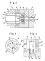
- a cylinder is designated 10.
- a flow chamber 12 is delimited within this cylinder.
- a mixing shaft 14 is arranged concentrically within the flow chamber 12 and is driven at its left end in FIG. 1 by a rotary drive 16.
- the mixing shaft 14 is supported in a bearing ring 18, which in turn is held in the cylinder 10 by a perforated plate or a spoke cross (not shown).
- An annular space 20 is enclosed between the mixing shaft 14 and the cylinder 10.
- the mixing shaft is designed in a first region A as a worm shaft 14a. In a second area B, the mixing shaft is smooth.
- the mixing shaft 14 is provided with mixing elements 22 which - as can be seen from FIG. 3 - are formed in the example by fins which are inserted in longitudinal grooves 24 of the mixing shaft 14.
- a material loading point 26 is attached to the cylinder. These comprises a feed cylinder 28 and a feed piston 30 guided in the feed cylinder. A material feed pipe connects to the feed cylinder.
- blocks or plates 34, 36 and 38 are flanged in a sandwich construction.
- An outflow chamber 40 is formed within the assembly formed by these blocks or plates, which is closed off by a sieve 42.
- a collection chamber 44 is formed in block 36, which is connected to a shut-off valve 46 in block 38.
- a channel 48 leads from the collecting chamber 44 via the shut-off valve 46 to a two-part mold 50.
- the two-part mold 50 can be detached from the plate 38 or can be pressed tightly against this plate.
- the mixing shaft 14 is surrounded by an annular piston 52 which can be pushed back and forth by force devices 54.
- the cylinder 10 is surrounded by annular radiators 56.
- the device described so far operates as follows: With the annular piston 52 retracted and the feed piston 30 retracted upward, raw material is introduced through the pipe 32 into the feed cylinder 28. The feed piston 30 pushes the raw material downwards.
- the screw conveyor 14a conveys the raw material in the annular space 20 to the right through the areas A, B and C.
- the heating elements 56 increasingly plasticize the raw material in the advancing direction to the right.
- the plasticized raw material is increasingly homogenized in the advancing direction to the right by the mixing elements 22.
- a filling of liquid to viscous material is formed in the partial area 58 indicated by horizontal lines, which also fills the outflow chamber 40.
- the raw material is in the partial area 60 still present in the consistency in which it is supplied. There is a transition consistency in area 62.
- the raw material is already partially plasticized, especially on the surface of the raw material particles.
- the loading point 26 is first closed.
- the raw material in the partial area 60 and in particular in the partial area 62 is compressed.
- the liquid to viscous thermoplastic material in the partial area 58 and in the outflow chamber 40 is pressed through the sieve 42 and flows into the mold 50 via the collecting chamber 44, the shut-off valve and the channel 48.
- the annular piston 52 is withdrawn again by the force devices 54. Start-up is now complete.
- the section 58, or at least the outflow chamber 40 contains constantly thermoplastic material.
- scrapers 70 are guided in block 36. These scrapers are designed in the form of cylindrical rods, which are each inserted into the block 36 through a bore 72 and can dip into the chamber 40. The scrapers lie with part of their circumference in grooves 74 in the sieve plate 42, from which the sieve bores 42a extend. When the scrapers 70 assume the upper position shown in FIG. 1 within the flow chamber 40, the screen openings 42a are all open.
- secondary drain holes 76 are also aligned with the scrapers. As can be seen in FIG. 1, secondary drain pipes 78 adjoin these secondary drain bores 76. The secondary drain pipes 78 are surrounded by a heat sink 80. A clamping point 82 connects to the heat sink 80 at the bottom.
- the strand 84 is then pushed downwards by the scraper 70, the feed resistance being able to be set by appropriately setting the clamping point 82. With this advance of the strand 84, thermoplastic material which has entered the secondary drain hole 76 flows back into the outflow chamber 40 in the direction of the arrow 86.
- the strand 84 therefore has a very low content of usable thermoplastic material and consists essentially only of waste.
- scrapers 70 can work in a push-pull manner, so that regardless of the lifting cycle of the annular piston 52, part of the drain bores 42a of the sieve 36 is constantly open and the drain of the thermoplasticized cleaned material through the sieve 42 is constantly guaranteed. Since the impurities predominantly collect in the channels 74 under the action of the flow in the outflow chamber 40, a constant and complete separation of the impurities is ensured. Since the scrapers 70 are designed as rods with a constant cross section, no upward transport of contaminants is possible.
- the stroke of the annular piston 52 can be adjusted so that a mold 50 is just filled with each feed stroke. However, it is also possible to intermittently shut off the outflow of the thermoplastic mass through the channel 48 by means of the shut-off valve 46 during the feed stroke of the annular piston 52, so that different shapes can be filled in succession during a feed stroke. It is also possible to fill a mold by means of several successive feed strokes of the annular piston 52, namely when the performance of the device is too small in relation to the mold volume of the mold 50. The shut-off valve 46 can then also be shut off between successive feed means of the annular piston 52.
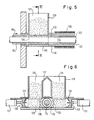
- FIGS. 5 and 6 show a modification of the loading area compared to FIG. 1. Analog parts are provided with the same reference numerals as in FIG. 1, each increased by the number 100.
- the charging housing 128, two charging pistons 130 are guided in opposite directions in the bottom region 129 by force devices 131. Each of the feed pistons 130 is provided with a half-cylinder surface 133.
- two charging chutes 135 are furthermore formed, which are separated from one another by a partition wall 137.
- the feed piston 130 is retracted (FIG. 6 - solid lines)
- the material to be processed falls from the feed chutes 135 into the enlarged spaces between the half-cylinder surfaces 133 and the mixing shaft 114.
Landscapes
- Engineering & Computer Science (AREA)
- Mechanical Engineering (AREA)
- Environmental & Geological Engineering (AREA)
- Processing And Handling Of Plastics And Other Materials For Molding In General (AREA)
Applications Claiming Priority (2)
| Application Number | Priority Date | Filing Date | Title |
|---|---|---|---|
| DE19883802719 DE3802719A1 (de) | 1988-01-29 | 1988-01-29 | Einrichtung zur herstellung von formkoerpern aus thermoplastischem werkstoff |
| DE3802719 | 1988-01-29 |
Publications (2)
| Publication Number | Publication Date |
|---|---|
| EP0326036A2 true EP0326036A2 (fr) | 1989-08-02 |
| EP0326036A3 EP0326036A3 (fr) | 1991-10-23 |
Family
ID=6346276
Family Applications (1)
| Application Number | Title | Priority Date | Filing Date |
|---|---|---|---|
| EP19890100986 Withdrawn EP0326036A3 (fr) | 1988-01-29 | 1989-01-20 | Dispositif pour la fabrication de corps thermoplastiques moulés |
Country Status (2)
| Country | Link |
|---|---|
| EP (1) | EP0326036A3 (fr) |
| DE (1) | DE3802719A1 (fr) |
Cited By (2)
| Publication number | Priority date | Publication date | Assignee | Title |
|---|---|---|---|---|
| EP0467842A1 (fr) * | 1990-07-17 | 1992-01-22 | GPW MACCHINE S.a.S. di GIUSEPPE PONZIELLI & C. | Procédé et appareil pour transférer et rendre compacts des particles solides |
| US5356280A (en) * | 1991-11-27 | 1994-10-18 | Gpw Machine S.A.S. Di Giuseppe Ponzielli & C. | Pump for particulate solids |
Families Citing this family (1)
| Publication number | Priority date | Publication date | Assignee | Title |
|---|---|---|---|---|
| DE202006018977U1 (de) * | 2006-12-15 | 2008-04-17 | Petersen Service Gmbh | Reinigungsvorrichtung |
Family Cites Families (10)
| Publication number | Priority date | Publication date | Assignee | Title |
|---|---|---|---|---|
| US1770396A (en) * | 1926-07-16 | 1930-07-15 | Joseph C Fuller | Machine for molding tubular material and method of producing same |
| US2485523A (en) * | 1943-07-21 | 1949-10-18 | Hpm Dev Corp | Hydraulic injection of plastics as a continuous strip |
| DE841057C (de) * | 1949-06-16 | 1952-06-13 | Friedrich Banz | Strangpresse |
| FR1195939A (fr) * | 1957-06-13 | 1959-11-20 | Battenfeld Maschfab | Dispositif de plastification et d'injection de matières synthétiques thermoplastiques |
| US3029471A (en) * | 1959-10-14 | 1962-04-17 | Owens Illinois Glass Co | Method and apparatus for making plastic articles |
| US3319297A (en) * | 1964-07-17 | 1967-05-16 | Goodrich Co B F | Injection molding machine |
| US3225963A (en) * | 1964-12-07 | 1965-12-28 | Vasken F Arpajian | Hopper apparatus and method |
| GB1573196A (en) * | 1975-12-15 | 1980-08-20 | Sumito Electric Ind Ltd | Method and apparatus for extruding polytetrafluoroethlene tubing |
| JPS5443985A (en) * | 1977-09-14 | 1979-04-06 | Nippon Ripuromashin Kougiyou K | Apparatus for removing foreign substance in synthetic resin recovering machine |
| US4177234A (en) * | 1977-10-05 | 1979-12-04 | Metals & Plastics, Inc. | Method and apparatus for cleaning thermoplastic materials |
-
1988
- 1988-01-29 DE DE19883802719 patent/DE3802719A1/de not_active Withdrawn
-
1989
- 1989-01-20 EP EP19890100986 patent/EP0326036A3/fr not_active Withdrawn
Cited By (3)
| Publication number | Priority date | Publication date | Assignee | Title |
|---|---|---|---|---|
| EP0467842A1 (fr) * | 1990-07-17 | 1992-01-22 | GPW MACCHINE S.a.S. di GIUSEPPE PONZIELLI & C. | Procédé et appareil pour transférer et rendre compacts des particles solides |
| US5223199A (en) * | 1990-07-17 | 1993-06-29 | Gpw Macchine S.A.S. Di Giuseppe Ponzielli & C. Of Via Vallone | Method of and apparatus for pumping particulate solids |
| US5356280A (en) * | 1991-11-27 | 1994-10-18 | Gpw Machine S.A.S. Di Giuseppe Ponzielli & C. | Pump for particulate solids |
Also Published As
| Publication number | Publication date |
|---|---|
| EP0326036A3 (fr) | 1991-10-23 |
| DE3802719A1 (de) | 1989-08-10 |
Similar Documents
| Publication | Publication Date | Title |
|---|---|---|
| DE60008411T2 (de) | Verfahren zur herstellung von formteilen | |
| EP0078064B1 (fr) | Appareil pour la séparation des matières de consistance différente | |
| DE2622001A1 (de) | Verfahren und vorrichtung zum herstellen von geschaeumtem kunststoff | |
| DE3121428C2 (de) | Spritzgießvorrichtung für plastifizierbare Massen, insbesondere mit Verstärkungsfasern | |
| DE3932416A1 (de) | Verfahren zum spritzgiessen von mehrkomponenten-kunststoffkoerpern und vorrichtung zur durchfuehrung des verfahrens | |
| EP4267368A1 (fr) | Technologie d'évacuation pour filtres à plastique | |
| DE2355458B1 (de) | Vorrichtung zum Spritzgießen von Kunststoffteilchen mit glatter Oberfläche und porigem Kern | |
| DE19653316A1 (de) | Verfahren und Vorrichtung zum Beeinflussen der Eigenschaften von aus formbarem Material hergestellten Artikeln | |
| DE69502853T2 (de) | Verfahren zum Spritzgiessen von gebogen geformten Hohlkörpern | |
| EP1631435B1 (fr) | Installation pour la preparation de matieres | |
| DE2128791A1 (de) | Verfahren und Vorrichtung zum Formpressen von Kunststoffen | |
| EP0326036A2 (fr) | Dispositif pour la fabrication de corps thermoplastiques moulés | |
| EP0204133B1 (fr) | Procédé pour fabriquer des objets en matière thermoplastique par moulage par injection | |
| DE2524746A1 (de) | Kunststoff-spritzgiessmaschine mit schneckenplastifizierung und massefilter | |
| EP0485909A1 (fr) | Dispositif pour compacter des récipients à petit volume pour liquides, spécialement des boîtes pour bière mal remplies ou des matériaux compactables similaires | |
| EP0656251A1 (fr) | Procédé et dispositif pour fabriquer des objets en matière plastique par moulage par injection | |
| DE2406569B2 (de) | Verfahren zum strangpressen oder spritzgiessen von thermoplastischen kunststoffen und vorrichtung zur durchfuehrung des verfahrens | |
| EP0160782A1 (fr) | Appareil pour la séparation de matières de consistance différente | |
| DE2633689A1 (de) | Verfahren und anlage zum formpressen von kunstharzgebundenen hochreibungsmaterialien | |
| DE2733245C3 (de) | Kunststoff-Spritzgießmaschine mit mehreren Spritzzylindern und mit umlaufenden Spritzgießformen | |
| EP0564690A1 (fr) | Procédé et dispositif pour la fabrication automatique d'objets en matière plastique, en particulier en matière plastique recyclée | |
| DE19849797A1 (de) | Injektor und Injektionsverfahren, insbesondere für thermoplastisches Material | |
| DE2312957B2 (de) | SpritzgieBmaschine zum Spritzgießen von Elastomeren | |
| DE3239030A1 (de) | Vorrichtung zum trennen von materialien unterschiedlicher konsistenz | |
| AT405920B (de) | Vorrichtung zum herstellen von begrenzungspfosten aus kunststoff |
Legal Events
| Date | Code | Title | Description |
|---|---|---|---|
| PUAI | Public reference made under article 153(3) epc to a published international application that has entered the european phase |
Free format text: ORIGINAL CODE: 0009012 |
|
| AK | Designated contracting states |
Kind code of ref document: A2 Designated state(s): AT BE CH DE ES FR GB GR IT LI LU NL SE |
|
| PUAL | Search report despatched |
Free format text: ORIGINAL CODE: 0009013 |
|
| AK | Designated contracting states |
Kind code of ref document: A3 Designated state(s): AT BE CH DE ES FR GB GR IT LI LU NL SE |
|
| 17P | Request for examination filed |
Effective date: 19920326 |
|
| 17Q | First examination report despatched |
Effective date: 19921001 |
|
| STAA | Information on the status of an ep patent application or granted ep patent |
Free format text: STATUS: THE APPLICATION IS DEEMED TO BE WITHDRAWN |
|
| 18D | Application deemed to be withdrawn |
Effective date: 19930414 |