EP0326052A2 - Method of making a pressure sealing between two chambers - Google Patents
Method of making a pressure sealing between two chambers Download PDFInfo
- Publication number
- EP0326052A2 EP0326052A2 EP89101075A EP89101075A EP0326052A2 EP 0326052 A2 EP0326052 A2 EP 0326052A2 EP 89101075 A EP89101075 A EP 89101075A EP 89101075 A EP89101075 A EP 89101075A EP 0326052 A2 EP0326052 A2 EP 0326052A2
- Authority
- EP
- European Patent Office
- Prior art keywords
- inner body
- outer body
- chamber pressure
- opening
- pressure pack
- Prior art date
- Legal status (The legal status is an assumption and is not a legal conclusion. Google has not performed a legal analysis and makes no representation as to the accuracy of the status listed.)
- Granted
Links
Images
Classifications
-
- B—PERFORMING OPERATIONS; TRANSPORTING
- B65—CONVEYING; PACKING; STORING; HANDLING THIN OR FILAMENTARY MATERIAL
- B65D—CONTAINERS FOR STORAGE OR TRANSPORT OF ARTICLES OR MATERIALS, e.g. BAGS, BARRELS, BOTTLES, BOXES, CANS, CARTONS, CRATES, DRUMS, JARS, TANKS, HOPPERS, FORWARDING CONTAINERS; ACCESSORIES, CLOSURES, OR FITTINGS THEREFOR; PACKAGING ELEMENTS; PACKAGES
- B65D83/00—Containers or packages with special means for dispensing contents
- B65D83/14—Containers for dispensing liquid or semi-liquid contents by internal gaseous pressure, i.e. aerosol containers comprising propellant
- B65D83/60—Containers for dispensing liquid or semi-liquid contents by internal gaseous pressure, i.e. aerosol containers comprising propellant with contents and propellant separated
- B65D83/62—Containers for dispensing liquid or semi-liquid contents by internal gaseous pressure, i.e. aerosol containers comprising propellant with contents and propellant separated by membranes, bags or the like
-
- B—PERFORMING OPERATIONS; TRANSPORTING
- B21—MECHANICAL METAL-WORKING WITHOUT ESSENTIALLY REMOVING MATERIAL; PUNCHING METAL
- B21D—WORKING OR PROCESSING OF SHEET METAL OR METAL TUBES, RODS OR PROFILES WITHOUT ESSENTIALLY REMOVING MATERIAL; PUNCHING METAL
- B21D51/00—Making hollow objects
- B21D51/16—Making hollow objects characterised by the use of the objects
- B21D51/24—Making hollow objects characterised by the use of the objects high-pressure containers, e.g. boilers, bottles
-
- B—PERFORMING OPERATIONS; TRANSPORTING
- B21—MECHANICAL METAL-WORKING WITHOUT ESSENTIALLY REMOVING MATERIAL; PUNCHING METAL
- B21D—WORKING OR PROCESSING OF SHEET METAL OR METAL TUBES, RODS OR PROFILES WITHOUT ESSENTIALLY REMOVING MATERIAL; PUNCHING METAL
- B21D51/00—Making hollow objects
- B21D51/16—Making hollow objects characterised by the use of the objects
- B21D51/26—Making hollow objects characterised by the use of the objects cans or tins; Closing same in a permanent manner
- B21D51/2615—Edge treatment of cans or tins
- B21D51/2623—Curling
-
- B—PERFORMING OPERATIONS; TRANSPORTING
- B21—MECHANICAL METAL-WORKING WITHOUT ESSENTIALLY REMOVING MATERIAL; PUNCHING METAL
- B21D—WORKING OR PROCESSING OF SHEET METAL OR METAL TUBES, RODS OR PROFILES WITHOUT ESSENTIALLY REMOVING MATERIAL; PUNCHING METAL
- B21D51/00—Making hollow objects
- B21D51/16—Making hollow objects characterised by the use of the objects
- B21D51/26—Making hollow objects characterised by the use of the objects cans or tins; Closing same in a permanent manner
- B21D51/2615—Edge treatment of cans or tins
- B21D51/2638—Necking
Definitions
- the invention relates to a method for producing a two-chamber pressure pack with an outer body, which encloses a pressurizable interior and forms an opening through which an inner body made of fold-forming or crushable material is used.
- Such two-chamber pressure packs are generally used today as a replacement for the known pressure containers with propellant gas.
- the medium is discharged from the inner body by pressurizing the interior of the outer body.
- the medium to be dispensed therefore does not come into contact with this pressure medium, but is expressed by changing the inner body through a valve.
- These known two-chamber pressure packs consist essentially of three parts, namely the outer body, for example an aluminum sleeve with a bottom, the inner body, for example a very thin aluminum sleeve and a funnel, which is placed on the mouth edge of the inner and outer body and surrounds it in a sealing manner. The corresponding valve is then inserted in the center of this disk-shaped funnel.
- Attaching the funnel to the mouth edges of the inner and outer body means a considerable amount of work, since this has to be done by hand.
- the funnel is rolled or flanged together with the mouth edges. That is why he needs a certain place. Since the valve itself usually also requires a diameter of 25 mm, the openings of today's two-chamber pressure packs must have a total diameter of around 40-65 mm. In between, only two-chamber pressure packs with graduated dimensions are used.
- the inventor has set itself the goal of developing a method of the type mentioned above, by means of which the attachment of the additional funnel becomes superfluous, in which the interior of the outer body can be kept absolutely tight and in which two-chamber pressure packs with different opening diameters from 1 Customs, d. H. can be produced from 25.4 mm.
- the outer body and inner body are connected to one another in a predetermined area before flanging or the like.
- connection is preferably made by welding, gluing, shaping or the like.
- a coating has proven to be the best here, which is applied either to the outer body or to the inner body or to both in the connection region before the inner body is inserted into the outer body.
- This coating for example a suitable adhesive, can then dry so that the inner body is inserted into the outer body without changing the coating.
- the two-chamber pressure pack preferably passes through an oven in which the coating is liquefied. This already creates a certain connection between the inner body and the outer body.
- the inner body since the inner body generally maintains a certain distance from the outer body in order to be surrounded by sufficient pressure medium in the position of use, it has proven to be advisable to insert a tool into the opening of the two-chamber pressure pack, via which the inner body in the corresponding connection area is pressed against the outer body.
- This tool can be heated so that the coating is liquefied or kept in motion by this heat.
- the mouth edges are then flanged, this preferably being done by rolling.
- the two-chamber pressure pack now only needs to be filled with the medium to be dispensed and the valve put on, through which the space of the inner body is now sealed, and the propellant gas has to be supplied via a bottom hole.
- This method according to the invention also has the advantage that both the outer body and the inner body can be printed, varnished or the like before the flanging.
- all standard interior protective lacquers can be used.
- the flanging can be done by means of an automatic machine, so that considerable labor is saved.
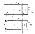
- a two-chamber pressure pack P has a sleeve-shaped outer body 1, which in the present exemplary embodiment essentially consists of a cylinder jacket 2 and a base cover 3.
- This outer body 1 can, for example, be produced from an aluminum blank in the extrusion or deep-drawing process.
- the bottom cover 3 has a bore 4 through which the interior I can be pressurized. After this process, the bore 4 can be closed.
- An inner body 6 is inserted into a cylinder opening 5 beyond the bottom cover 3 of the outer body 1.
- This inner body 6 also has a cylinder jacket 7 and a closed bottom cover 8.
- this inner body 6 consists of a relatively thin aluminum, so that it can be crushed with the formation of folds.
- Cylinder jacket 7 and base cover 8 enclose a space R, which in the position of use serves to receive a medium to be dispensed.
- the inner body 6 maintains a distance a from the cylinder jacket 2 of the outer body 1 over long distances.
- inner body 6 or its cylinder jacket 7 is connected to cylinder jacket 2 in area b.
- the connection is made, for example, by welding, gluing, laser welding, shaping or the like.
- This preliminary stage of a two-chamber pressure pack according to the invention is produced as follows:
- the outer body 1 is drawn from an aluminum blank.
- the hole 4 is made in the bottom cover 3 and the cylinder jacket 2 is covered or welded with a coating 9 of an adhesive over the region b.
- the inner body 6 is inserted, the coating 9 being solidified so that it does not hinder insertion.
- the two-chamber pressure pack P now passes through an oven in which the coating 9 is liquefied. As a result, a connection between cylinder jacket 2 and cylinder jacket 7 is already initiated. However, the correct connection produces a heated tool which is inserted through the cylinder opening 5 and presses the cylinder jacket 7 in region b against the cylinder jacket 2.
- the next processing stage is shown in FIG. 2.
- the bottom cover 3 is deformed so that it can withstand an internal pressure in the interior I and does not bulge.
- cylinder jacket 2 and cylinder jacket 7 are flanged outwards in the region of the cylinder opening 5, so that a flanged edge 10 is created.
- cylinder jacket 2 and cylinder jacket 7 are simultaneously pulled inwards in a specific area.
- the space R of the inner body 6 is now filled with the substance to be dispensed and the cylinder opening 5 is closed by a cover with a valve, not shown. This lid seals the flange 10.
- the interior I of the outer body 1 is then pressurized through the bore 4, the bore 4 then being closed.
- the inner body 6 is pressurized, so that when the valve is actuated, the medium is discharged from the space R of the inner body 6 through the valve, while the inner body 6 yields to the same extent to the pressure in the interior of the outer body 1 and crumples .
Landscapes
- Mechanical Engineering (AREA)
- Engineering & Computer Science (AREA)
- Chemical & Material Sciences (AREA)
- Dispersion Chemistry (AREA)
- Containers And Packaging Bodies Having A Special Means To Remove Contents (AREA)
- Gasket Seals (AREA)
- Filling Or Discharging Of Gas Storage Vessels (AREA)
- Auxiliary Devices For And Details Of Packaging Control (AREA)
- Joining Of Glass To Other Materials (AREA)
- Glass Compositions (AREA)
- Nozzles (AREA)
- Packages (AREA)
- Infusion, Injection, And Reservoir Apparatuses (AREA)
- Crystals, And After-Treatments Of Crystals (AREA)
- Particle Formation And Scattering Control In Inkjet Printers (AREA)
- Closures For Containers (AREA)
- Press Drives And Press Lines (AREA)
Abstract
Bei einem Verfahren zum Herstellen einer Zweikammer-Druckpackung (P) mit einem Außenkörper (1), der einen druckbeaufschlagbaren Innenraum (I) umschließt und eine Öffnung (5) ausbildet, wird durch diese Öffnung ein Innenkörper (6) aus faltenbildendem bzw. knautschbarem Material eingesetzt. Außenkörper (1) und Innenkörper (6) werden vor einem Bördeln od. dgl. der Öffnung, einem Befüllen des Innenkörpers und einem Anbringen eines Ventils im Mündungsbereich in einem vorbestimmten Bereich (B) miteinander verbunden und sodann zusammen zu einem Bördelrand umgelegt. 
Description
Die Erfindung betrifft ein Verfahren zum Herstellen einer Zweikammer-Druckpackung mit einem Außenkörper, der einen druckbeaufschlagbaren Innenraum umschließt und eine Öffnung ausbildet, durch die ein Innenkörper aus faltenbildendem bzw. knautschbarem Material eingesetzt wird.The invention relates to a method for producing a two-chamber pressure pack with an outer body, which encloses a pressurizable interior and forms an opening through which an inner body made of fold-forming or crushable material is used.
Derartige Zweikammer-Druckpackungen werden heute in der Regel als Ersatz für die bekannten Druckbehälter mit Treibgas verwendet. Das Ausbringen des Mediums aus dem Innenkörper geschieht durch die Druckbeaufschlagung des Innenraums des Außenkörpers. Das auszubringende Medium gelangt deshalb nicht in Kontakt mit diesem Druckmedium, sondern wird durch Veränderung des Innenkörpers durch ein Ventil ausgedrückt.Such two-chamber pressure packs are generally used today as a replacement for the known pressure containers with propellant gas. The medium is discharged from the inner body by pressurizing the interior of the outer body. The medium to be dispensed therefore does not come into contact with this pressure medium, but is expressed by changing the inner body through a valve.
Diese bekannten Zweikammer-Druckpackungen bestehen im wesentlichen aus drei Teilen, nämlich dem Außenkörper, beispielsweise einer Aluminiumhülse mit Boden, dem Innenkörper, beispielsweise einer sehr dünnen Aluminiumhülse sowie einem Trichter, welcher auf den Mündungsrand von Innen- und Außenkörper aufgesetzt ist und diesen abdichtend umschließt. In diesen scheibenförmigen Trichter ist dann mittig das entsprechende Ventil eingesetzt.These known two-chamber pressure packs consist essentially of three parts, namely the outer body, for example an aluminum sleeve with a bottom, the inner body, for example a very thin aluminum sleeve and a funnel, which is placed on the mouth edge of the inner and outer body and surrounds it in a sealing manner. The corresponding valve is then inserted in the center of this disk-shaped funnel.
Gerade das Anbringen des Trichters auf die Mündungsränder von Innen- und Außenkörper bedeutet einen erheblichen Arbeitsaufwand, da dieses von Hand geschehen muß. Der Trichter wird zusammen mit den Mündungsrändern gerollt oder gebördelt. Deshalb benötigt er einen bestimmten Platz. Da das Ventil selbst ebenfalls in der Regel 25 mm Durchmesser benötigt, müssen die Öffnungen der heutigen Zweikammer-Druckpackungen insgesamt etwa 40-65 mm Durchmesser aufweisen. Dazwischen finden lediglich Zweikammer-Druckpackungen mit abgestuften Bemaßungen Anwendung.Attaching the funnel to the mouth edges of the inner and outer body means a considerable amount of work, since this has to be done by hand. The funnel is rolled or flanged together with the mouth edges. That is why he needs a certain place. Since the valve itself usually also requires a diameter of 25 mm, the openings of today's two-chamber pressure packs must have a total diameter of around 40-65 mm. In between, only two-chamber pressure packs with graduated dimensions are used.
Der Erfinder hat sich zum Ziel gesetzt, ein Verfahren der oben genannten Art zu entwickeln, mittels welchem das Anbringen des zusätzlichen Trichters überflüssig wird, bei welchem der Innenraum des Außenkörpers absolut dicht gehalten werden kann und bei welchem Zweikammer-Druckpackungen mit unterschiedlichen Öffnungsdurchmessern bereits ab 1 Zoll, d. h. ab 25,4 mm hergestellt werden können.The inventor has set itself the goal of developing a method of the type mentioned above, by means of which the attachment of the additional funnel becomes superfluous, in which the interior of the outer body can be kept absolutely tight and in which two-chamber pressure packs with different opening diameters from 1 Customs, d. H. can be produced from 25.4 mm.
Zur Lösung dieser Aufgabe führt, daß der Außenkörper und Innenkörper vor einem Bördeln od. dgl. der Öffnung, einem Befüllen des Innenkörpers und einem Anbringen eines Ventils im Mündungsbereich in einem vorbestimmten Bereich miteinander verbunden und sodann zusammen zu einem Bördelrand umgelegt werden.To achieve this object, the outer body and inner body are connected to one another in a predetermined area before flanging or the like. The opening, filling the inner body and attaching a valve and then folded together to form a flanged edge.
Dies bedeutet, daß bereits vor der Erzeugung des Bördelrandes eine leckagenfreie Verbindung zwischen Innenkörper und Außenkörper hergestellt und somit der druckbeaufschlagbare Innenraum absolut dicht gehalten wird.This means that a leak-free connection between the inner body and the outer body is established even before the flanged edge is produced, and the interior which can be pressurized is thus kept absolutely tight.
Bevorzugt erfolgt die Verbindung durch Schweißen, Kleben, Verformen od. dgl.. Am besten hat sich hier eine Beschichtung erwiesen, welche entweder dem Außenkörper oder dem Innenkörper oder beiden in dem Verbindungsbereich vor dem Einsetzen des Innenkörpers in den Außenkörper aufgebracht wird. Diese Beschichtung, beispielsweise ein geeigneter Klebstoff, kann dann trocknen, so daß ohne Veränderung der Beschichtung der Innenkörper in den Außenkörper eingesetzt wird. Nach dem Einsetzen durchläuft die Zweikammer-Druckpackung bevorzugt einen Ofen, in welchem die Beschichtung verflüssigt wird. Hierdurch wird bereits eine gewisse Verbindung zwischen Innenkörper und Außenkörper hergestellt. Da aber in der Regel der Innenkörper einen bestimmten Abstand vom Außenkörper einhält, um in Gebrauchslage von genügendem Druckmedium umgeben zu sein, hat es sich als ratsam erwiesen, in die Öffnung der Zweikammer-Druckpackung ein Werkzeug einzuführen, über welches der Innenkörper in dem entsprechenden Verbindungsbereich gegen den Außenkörper gedrückt wird. Dieses Werkzeug kann geheizt sein, damit über diese Wärme die Verflüssigung der Beschichtung erfolgt bzw. in Gang gehalten wird.The connection is preferably made by welding, gluing, shaping or the like. A coating has proven to be the best here, which is applied either to the outer body or to the inner body or to both in the connection region before the inner body is inserted into the outer body. This coating, for example a suitable adhesive, can then dry so that the inner body is inserted into the outer body without changing the coating. After insertion, the two-chamber pressure pack preferably passes through an oven in which the coating is liquefied. This already creates a certain connection between the inner body and the outer body. However, since the inner body generally maintains a certain distance from the outer body in order to be surrounded by sufficient pressure medium in the position of use, it has proven to be advisable to insert a tool into the opening of the two-chamber pressure pack, via which the inner body in the corresponding connection area is pressed against the outer body. This tool can be heated so that the coating is liquefied or kept in motion by this heat.
Nach dem Herstellen der Verbindung zwischen Innenkörper und Außenkörper erfolgt dann ein Umbördeln der Mündungsränder, wobei dies bevorzugt durch Rollen geschieht.After the connection between the inner body and outer body has been established, the mouth edges are then flanged, this preferably being done by rolling.
Nunmehr ist der Innenraum absolut dicht. Sollten wider Erwarten Leckagen im Bereich der Verbindung auftreten, so kann zusätzliches Dichtungsmaterial durch die Öffnung, welche auch zur Druckbeaufschlagung des Innenraums dient, eingefüllt werden, welche dann an den Innenwänden des Außenkörpers entlangfließt und so die Beschichtung des Verbindungsbereiches ergänzt.Now the interior is absolutely tight. If, contrary to expectations, leakage occurs in the area of the connection, additional sealing material can be filled through the opening, which also serves to pressurize the interior, which then flows along the inner walls of the outer body and thus complements the coating of the connection area.
Im letzten Arbeitsgang braucht nunmehr die Zweikammer-Druckpackung nur noch mit dem auszubringenden Medium gefüllt und das Ventil aufgesetzt zu werden, durch welches jetzt auch der Raum des Innenkörpers abgedichtet ist, sowie über ein Bodenloch das Treibgas zugeführt zu werden.In the last step, the two-chamber pressure pack now only needs to be filled with the medium to be dispensed and the valve put on, through which the space of the inner body is now sealed, and the propellant gas has to be supplied via a bottom hole.
Dieses erfindungsgemäße Verfahren hat ferner den Vorteil, daß sowohl Außenkörper wie auch Innenkörper bereits vor dem Bördeln fertig bedruckt, lackiert od. dgl. sein können. Außerdem können im Gegensatz zu den bisher üblichen Trichtern sämtliche Standard-Innenschutzlacke Verwendung finden. Das Bördeln kann mittels eine Automaten erfolgen, so daß erhebliche Arbeitskräfte eingespart werden.This method according to the invention also has the advantage that both the outer body and the inner body can be printed, varnished or the like before the flanging. In addition, in contrast to the hoppers previously used, all standard interior protective lacquers can be used. The flanging can be done by means of an automatic machine, so that considerable labor is saved.
Weitere Vorteile, Merkmale und Einzelheiten der Erfindung ergeben sich aus der nachfolgenden Beschreibung bevorzugter Ausführungsbeispiele sowie anhand der Zeichnung; diese zeigt in
- Fig. 1 einen Längsschnitt durch eine erfindungsgemäße Zwekammer-Druckpackung in einem Vorstadium der Herstellung;
- Fig. 2 einen weiteren Längsschnitt durch die Zweikammer-Druckpackung nach Fig. 1 in einem weiteren Stadium der Herstellung.
- 1 shows a longitudinal section through a two-chamber pressure pack according to the invention in a preliminary stage of manufacture.
- Fig. 2 shows a further longitudinal section through the two-chamber pressure pack according to Fig. 1 in a further stage of manufacture.
Eine erfindungsgemäße Zweikammer-Druckpackung P besitzt einen hülsenförmigen Außenkörper 1, welcher im wesentlichen im vorliegenden Ausführungsbeispiel aus einem Zylindermantel 2 sowie einem Bodendeckel 3 besteht. Dieser Außenkörper 1 kann beispielsweise im Fließpreß- oder Tiefziehverfahren aus einer Aluminiumronde hergestellt sein. Der Bodendeckel 3 besitzt eine Bohrung 4, über welche der Innenraum I unter Druck gesetzt werden kann. Nach diesem Vorgang kann die Bohrung 4 verschlossen werden.A two-chamber pressure pack P according to the invention has a sleeve-shaped
In eine Zylinderöffnung 5 jenseits des Bodendeckels 3 des Außenkörpers 1 ist ein Innenkörper 6 eingesetzt. Dieser Innenkörper 6 besitzt ebenfalls einen Zylindermantel 7 sowie einen geschlossenen Bodendeckel 8. Insgesamt besteht dieser Innenkörper 6 aus einem verhältnismäßig dünnen Aluminium, so daß er unter Faltenbildung knautschbar ist.An
Zylindermantel 7 und Bodendeckel 8 umfangen einen Raum R, welcher in Gebrauchslage zur Aufnahme eines auszubringenden Mediums dient.Cylinder jacket 7 and base cover 8 enclose a space R, which in the position of use serves to receive a medium to be dispensed.
Im vorliegenden Ausführungsbeispiel hält der Innenkörper 6 von dem Zylindermantel 2 des Außenkörpers 1 über weite Strecken einen Abstand a ein. Zur Zylinderöffnung 5 hin, d. h. im Mündungsbereich von Außenkörper 1 und Innenkörper 6 ist jedoch der Innenkörper 6 bzw. dessen Zylindermantel 7 mit dem Zylindermantel 2 im Bereich b verbunden. Die Verbindung erfolgt beispielsweise über Schweißen, Kleben, Laserschweißen, Verformen od. dgl..In the present exemplary embodiment, the
Die Herstellung dieses erfindungsgemäßen Vorstadiums einer Zweikammer-Druckpackung geschieht folgendermaßen:This preliminary stage of a two-chamber pressure pack according to the invention is produced as follows:
Aus einer Aluminiumronde wird der Außenkörper 1 gezogen. In den Bodendeckel 3 wird die Bohrung 4 eingebracht und der Zylindermantel 2 über den Bereich b mit einer Beschichtung 9 eines Klebstoffes belegt oder geschweißt.The
Danach erfolgt das Einsetzen des Innenkörpers 6, wobei die Beschichtung 9 verfestigt ist, so daß sie ein Einsetzen nicht behindert.Then the
Nun durchläuft die Zweikammer-Druckpackung P einen Ofen, in welchem die Beschichtung 9 verflüssigt wird. Hierdurch wird bereits eine Verbindung zwischen Zylindermantel 2 und Zylindermantel 7 eingeleitet. Die ordnungsgemäße Verbindung erzeugt jedoch ein geheiztes Werkzeug, welches durch die Zylinderöffnung 5 eingeführt wird und den Zylindermantel 7 im Bereich b gegen den Zylindermantel 2 drückt.The two-chamber pressure pack P now passes through an oven in which the
Die nächste Bearbeitungsstufe ist in Fig. 2 gezeigt. In dieser Bearbeitungsstufe wird zum einen der Bodendeckel 3 verformt, so daß er einem Innendruck in dem Innenraum I widerstehen kann und sich nicht auswölbt.The next processing stage is shown in FIG. 2. In this processing stage, on the one hand, the
Des weiteren werden Zylindermantel 2 und Zylindermantel 7 im Bereich der Zylinderöffnung 5 nach außen umgebördelt, so daß ein Bördelrand 10 entsteht. Hierbei werden gleichzeitig Zylindermantel 2 und Zylindermantel 7 in einem bestimmten Bereich nach innen gezogen.Furthermore,
In einem weiteren Stadium der Herstellung wird nun der Raum R des Innenkörpers 6 mit dem auszubringenden Stoff gefüllt und die Zylinderöffnung 5 durch einen nicht gezeigten Deckel mit Ventil verschlossen. Dieser Deckel dichtet den Bördelrand 10 ab. Danach wird der Innenraum I des Außenkörpers 1 durch die Bohrung 4 unter Druck gesetzt, wobei anschließend die Bohrung 4 verschlossen wird. Gleichzeitig ist aber auch der Innenkörper 6 unter Druck gesetzt, so daß bei einer Betätigung des Ventils das Medium aus dem Raum R des Innenkörpers 6 durch das Ventil ausgebracht wird, während der Innenkörper 6 im gleichen Umfang dem Druck im Innenraum des Außenkörpers 1 nachgibt und zusammenknautscht.In a further stage of production, the space R of the
Sollte sich herausstellen, daß im Bereich der Beschichtung 9 Leckagen bei Druckbeaufschlagung des Innenraums I des Außenkörpers 1 entstehen, so besteht die Möglichkeit, durch die Bohrung 4 weiteres Dichtungsmaterial in den Innenraum I einzubringen. Dieses fließt entlang dem Zylindermantel 2 zu der Beschichtung 9, so daß Leckagen auch nachträglich beseitigt werden können.If it turns out that there are leakages in the area of the
Claims (10)
dadurch gekennzeichnet,
daß Außenkörper und Innenkörper vor einem Bördeln od. dgl. der Öffnung, einem Befüllen des Innenkörpers und einem Anbringen eines Ventils im Mündungsbereich in einem vorbestimmten Bereich miteinander verbunden und sodann zusammen zu einem Bördelrand umgelegt werden.1. A method for producing a two-chamber pressure pack with an outer body which encloses an interior which can be pressurized and forms an opening through which an inner body made of fold-forming or crushable material is used,
characterized,
that the outer body and inner body are connected to one another in a predetermined area before flanging or the like. The opening, filling the inner body and attaching a valve and then folded together to form a flanged edge.
Priority Applications (1)
| Application Number | Priority Date | Filing Date | Title |
|---|---|---|---|
| AT89101075T ATE83953T1 (en) | 1988-01-27 | 1989-01-23 | PROCEDURE FOR MANUFACTURING A DUAL PRESSURE CHAMBER. |
Applications Claiming Priority (2)
| Application Number | Priority Date | Filing Date | Title |
|---|---|---|---|
| DE3802314A DE3802314C1 (en) | 1988-01-27 | 1988-01-27 | |
| DE3802314 | 1988-01-27 |
Publications (3)
| Publication Number | Publication Date |
|---|---|
| EP0326052A2 true EP0326052A2 (en) | 1989-08-02 |
| EP0326052A3 EP0326052A3 (en) | 1990-09-12 |
| EP0326052B1 EP0326052B1 (en) | 1992-12-30 |
Family
ID=6346062
Family Applications (1)
| Application Number | Title | Priority Date | Filing Date |
|---|---|---|---|
| EP89101075A Expired - Lifetime EP0326052B1 (en) | 1988-01-27 | 1989-01-23 | Method of making a pressure sealing between two chambers |
Country Status (18)
| Country | Link |
|---|---|
| US (1) | US5069590A (en) |
| EP (1) | EP0326052B1 (en) |
| JP (1) | JP2873691B2 (en) |
| AT (1) | ATE83953T1 (en) |
| AU (1) | AU617412B2 (en) |
| BR (1) | BR8900323A (en) |
| CA (1) | CA1316407C (en) |
| DE (2) | DE3802314C1 (en) |
| DK (1) | DK168589B1 (en) |
| ES (1) | ES2037884T3 (en) |
| FI (1) | FI94845C (en) |
| GR (1) | GR3006763T3 (en) |
| HK (1) | HK56593A (en) |
| LT (1) | LT3830B (en) |
| LV (1) | LV11055B (en) |
| NO (1) | NO173646C (en) |
| RU (1) | RU2027098C1 (en) |
| ZA (1) | ZA89670B (en) |
Cited By (11)
| Publication number | Priority date | Publication date | Assignee | Title |
|---|---|---|---|---|
| EP0547982A1 (en) * | 1991-12-17 | 1993-06-23 | Cebal S.A. | Method of manufacturing a spreader body with a metal pouch, spreader body and corresponding spreader |
| EP0743255A1 (en) * | 1995-05-19 | 1996-11-20 | Gerd Stoffel | Method to produce a dual-compartment pressurized pack |
| EP0755877A1 (en) * | 1995-07-28 | 1997-01-29 | IPC Packaging AG | Dual compartment receptacle with tapered inner receptacle |
| WO1999020543A1 (en) * | 1997-10-17 | 1999-04-29 | Lechner Gmbh | Method for producing a two chamber pressure pack and a device for carrying out the same |
| RU2131389C1 (en) * | 1994-04-18 | 1999-06-10 | Герд Штоффель | Method of manufacture of two-chamber container with medium under pressure |
| WO1999059896A1 (en) * | 1998-05-20 | 1999-11-25 | Cebal S.A. | Pressurised dispenser body comprising a metal or copper-asbestos pocket, said pocket and method for obtaining same |
| FR2820127A1 (en) | 2001-01-30 | 2002-08-02 | Pechiney Emballage Alimentaire | Container/dispenser for product in liquid to paste form has inner metal or metal/plastic pouch that is both inflatable and collapsible |
| EP1468759A1 (en) * | 2003-04-15 | 2004-10-20 | Nussbaum Rielasingen GmbH | Method for manufacturing a double chamber pressure container |
| DE102007050333A1 (en) | 2007-10-18 | 2009-04-23 | Nussbaum Rielasingen Gmbh | Method for producing a two-chamber pressure vessel |
| US10239648B2 (en) | 2014-10-28 | 2019-03-26 | Ball Metalpack, Llc | Apparatus and method for forming a cup with a reformed bottom |
| US10315242B2 (en) | 2014-10-15 | 2019-06-11 | Ball Metalpack, Llc | Apparatus and method for simultaneously forming a contoured shoulder and neck portion in a closed end of a metallic container |
Families Citing this family (19)
| Publication number | Priority date | Publication date | Assignee | Title |
|---|---|---|---|---|
| DE3915765C2 (en) * | 1988-01-27 | 1998-07-30 | Gerd Stoffel | Process for producing a two-chamber pressure pack |
| DE4023602A1 (en) * | 1990-07-25 | 1992-01-30 | Majer Christian Gmbh Co Kg | Cardboard container with aluminium lining - has foil which can be easily detached to facilitate recycling of cardboard and foil |
| DE19746017C2 (en) * | 1997-10-17 | 2000-12-21 | Lechner Gmbh | Method and device for producing a two-chamber pressure pack |
| DE19932680C2 (en) * | 1999-06-10 | 2001-07-26 | Lechner Gmbh | Method and device for producing a two-chamber pressure pack |
| EP1059129A3 (en) * | 1999-06-10 | 2001-09-26 | LECHNER GmbH, Fabrik für Aluminium-Verpackungen | Method and device for producing a two chamber pressure pack, forming tool used therein and two chamber pressure pack produced therewith |
| DE10017021B4 (en) * | 2000-04-05 | 2008-10-16 | Linnemann-Schnetzer Gmbh | Method for producing a container for receiving a pressurized medium and pressure vessel |
| DE10207129B4 (en) * | 2002-02-20 | 2004-04-01 | Lechner Gmbh | Method and device for manufacturing a pressure pack container |
| DE10222749B4 (en) * | 2002-05-23 | 2009-04-02 | Hilti Aktiengesellschaft | pressure vessel |
| EP1422052B1 (en) * | 2002-11-20 | 2009-05-13 | Joaquin Devesa Company | Procedure for construction of multi-layer cylindrical containers and containers so obtained |
| DE10318576B3 (en) * | 2003-04-24 | 2004-11-25 | Hilti Ag | Pressure vessel and method for manufacturing and / or filling a pressure vessel |
| DE10321765B4 (en) * | 2003-05-15 | 2007-10-11 | Hilti Ag | Method for producing and filling a pressure vessel and pressure vessel |
| DE10326474B4 (en) * | 2003-06-12 | 2008-04-17 | Hilti Ag | pressure vessel |
| FR2884894B1 (en) * | 2005-04-22 | 2007-06-29 | Prospection Et D Inv S Techniq | COMBUSTION GAS CARTRIDGE FOR GAS FIXING APPARATUS |
| JP4877504B2 (en) | 2006-01-27 | 2012-02-15 | マックス株式会社 | Gas cartridge |
| JP5103871B2 (en) | 2006-01-27 | 2012-12-19 | マックス株式会社 | Gas cartridge |
| JP5223186B2 (en) | 2006-01-27 | 2013-06-26 | マックス株式会社 | Gas cartridge |
| DE102007062471A1 (en) | 2007-12-20 | 2009-06-25 | Krones Ag | Apparatus and method for applying labels |
| RU2449206C1 (en) * | 2010-09-03 | 2012-04-27 | Открытое акционерное общество "Газпром" | Double-cavity pressure vessel with varying volume of cavities |
| CN108290676A (en) * | 2015-10-01 | 2018-07-17 | 普莱斯博制造有限公司 | metered dose inhaler canister and sheath |
Family Cites Families (9)
| Publication number | Priority date | Publication date | Assignee | Title |
|---|---|---|---|---|
| FR2140804A5 (en) * | 1971-06-08 | 1973-01-19 | Scal Gp Condit Aluminium | |
| US3974945A (en) * | 1975-01-27 | 1976-08-17 | Norman D. Burger | Aerosol dispensing system |
| GB1508509A (en) * | 1975-05-07 | 1978-04-26 | Cebal | Pressurized dispensing container of the type having an inner flexible container and method for manufacturing same |
| FR2310287A1 (en) * | 1975-05-07 | 1976-12-03 | Cebal | Aerosol container with inner flexible bag - has inner bag flange held on washer on rigid outer body rim of same internal dia. |
| SE404346B (en) * | 1976-02-27 | 1978-10-02 | Rhenag Ag | KERL FOR RECEPTION AND DELIVERY OF LIQUID AND PASTA-MASSES UNDER PRESSURE |
| US4308973A (en) * | 1978-06-30 | 1982-01-05 | The Continental Group, Inc. | Compartmented aerosol container |
| US4185758A (en) * | 1978-08-01 | 1980-01-29 | The Continental Group, Inc. | Compartmentalized aerosol container |
| DE2912670A1 (en) * | 1979-03-30 | 1980-10-09 | Lechner Gmbh | TWO-CHAMBER PRESSURE CAN FOR DISPENSING A FILLING MATERIAL |
| JPS6023174A (en) * | 1983-07-18 | 1985-02-05 | ライオン株式会社 | Pressure type double vessel and manufacture thereof |
-
1988
- 1988-01-27 DE DE3802314A patent/DE3802314C1/de not_active Expired
- 1988-12-29 FI FI886033A patent/FI94845C/en not_active IP Right Cessation
-
1989
- 1989-01-04 NO NO890024A patent/NO173646C/en unknown
- 1989-01-12 JP JP1003725A patent/JP2873691B2/en not_active Expired - Lifetime
- 1989-01-20 CA CA000588837A patent/CA1316407C/en not_active Expired - Fee Related
- 1989-01-23 AT AT89101075T patent/ATE83953T1/en not_active IP Right Cessation
- 1989-01-23 ES ES198989101075T patent/ES2037884T3/en not_active Expired - Lifetime
- 1989-01-23 EP EP89101075A patent/EP0326052B1/en not_active Expired - Lifetime
- 1989-01-23 RU SU894613274A patent/RU2027098C1/en active
- 1989-01-23 DE DE8989101075T patent/DE58903132D1/en not_active Expired - Fee Related
- 1989-01-25 DK DK031189A patent/DK168589B1/en not_active IP Right Cessation
- 1989-01-26 BR BR898900323A patent/BR8900323A/en not_active IP Right Cessation
- 1989-01-26 AU AU28883/89A patent/AU617412B2/en not_active Ceased
- 1989-01-27 ZA ZA89670A patent/ZA89670B/en unknown
-
1990
- 1990-10-26 US US07/605,110 patent/US5069590A/en not_active Expired - Fee Related
-
1993
- 1993-01-11 GR GR930400019T patent/GR3006763T3/el unknown
- 1993-06-10 HK HK565/93A patent/HK56593A/en not_active IP Right Cessation
- 1993-06-28 LV LVP-93-695A patent/LV11055B/en unknown
-
1994
- 1994-01-13 LT LTIP1765A patent/LT3830B/en not_active IP Right Cessation
Cited By (14)
| Publication number | Priority date | Publication date | Assignee | Title |
|---|---|---|---|---|
| EP0547982A1 (en) * | 1991-12-17 | 1993-06-23 | Cebal S.A. | Method of manufacturing a spreader body with a metal pouch, spreader body and corresponding spreader |
| RU2131389C1 (en) * | 1994-04-18 | 1999-06-10 | Герд Штоффель | Method of manufacture of two-chamber container with medium under pressure |
| DE4413331B4 (en) * | 1994-04-18 | 2004-07-29 | Gerd Stoffel | Process for producing a two-chamber pressure pack |
| EP0743255A1 (en) * | 1995-05-19 | 1996-11-20 | Gerd Stoffel | Method to produce a dual-compartment pressurized pack |
| EP0755877A1 (en) * | 1995-07-28 | 1997-01-29 | IPC Packaging AG | Dual compartment receptacle with tapered inner receptacle |
| WO1999020543A1 (en) * | 1997-10-17 | 1999-04-29 | Lechner Gmbh | Method for producing a two chamber pressure pack and a device for carrying out the same |
| DE19746018C2 (en) * | 1997-10-17 | 2000-12-21 | Lechner Gmbh | Process for producing a two-chamber pressure pack and device for carrying out the process |
| DE19746018A1 (en) * | 1997-10-17 | 1999-04-29 | Lechner Gmbh | Two-chamber aerosol can manufacture |
| WO1999059896A1 (en) * | 1998-05-20 | 1999-11-25 | Cebal S.A. | Pressurised dispenser body comprising a metal or copper-asbestos pocket, said pocket and method for obtaining same |
| FR2820127A1 (en) | 2001-01-30 | 2002-08-02 | Pechiney Emballage Alimentaire | Container/dispenser for product in liquid to paste form has inner metal or metal/plastic pouch that is both inflatable and collapsible |
| EP1468759A1 (en) * | 2003-04-15 | 2004-10-20 | Nussbaum Rielasingen GmbH | Method for manufacturing a double chamber pressure container |
| DE102007050333A1 (en) | 2007-10-18 | 2009-04-23 | Nussbaum Rielasingen Gmbh | Method for producing a two-chamber pressure vessel |
| US10315242B2 (en) | 2014-10-15 | 2019-06-11 | Ball Metalpack, Llc | Apparatus and method for simultaneously forming a contoured shoulder and neck portion in a closed end of a metallic container |
| US10239648B2 (en) | 2014-10-28 | 2019-03-26 | Ball Metalpack, Llc | Apparatus and method for forming a cup with a reformed bottom |
Also Published As
| Publication number | Publication date |
|---|---|
| JP2873691B2 (en) | 1999-03-24 |
| NO173646B (en) | 1993-10-04 |
| GR3006763T3 (en) | 1993-06-30 |
| DE58903132D1 (en) | 1993-02-11 |
| US5069590A (en) | 1991-12-03 |
| LT3830B (en) | 1996-04-25 |
| RU2027098C1 (en) | 1995-01-20 |
| ATE83953T1 (en) | 1993-01-15 |
| NO173646C (en) | 1994-01-12 |
| BR8900323A (en) | 1989-09-19 |
| DE3802314C1 (en) | 1989-10-26 |
| NO890024L (en) | 1989-07-28 |
| DK31189D0 (en) | 1989-01-25 |
| AU617412B2 (en) | 1991-11-28 |
| ES2037884T3 (en) | 1993-07-01 |
| FI886033L (en) | 1989-07-28 |
| EP0326052B1 (en) | 1992-12-30 |
| FI94845C (en) | 1995-11-10 |
| LTIP1765A (en) | 1995-07-25 |
| HK56593A (en) | 1993-06-18 |
| DK168589B1 (en) | 1994-05-02 |
| FI94845B (en) | 1995-07-31 |
| EP0326052A3 (en) | 1990-09-12 |
| LV11055A (en) | 1996-02-20 |
| LV11055B (en) | 1996-04-20 |
| JPH024466A (en) | 1990-01-09 |
| DK31189A (en) | 1989-07-28 |
| AU2888389A (en) | 1989-07-27 |
| ZA89670B (en) | 1989-10-25 |
| NO890024D0 (en) | 1989-01-04 |
| CA1316407C (en) | 1993-04-20 |
Similar Documents
| Publication | Publication Date | Title |
|---|---|---|
| EP0326052A2 (en) | Method of making a pressure sealing between two chambers | |
| DE2353209C2 (en) | Method for producing a one-piece container made of metal, open at one end, in particular a metal can | |
| DE2409912C3 (en) | Method for inserting a pot-shaped metallic base in a metallic container body | |
| DE3534326C2 (en) | ||
| DE2113235C3 (en) | Method and device for forming an integral tubular rivet on a sheet metal part | |
| DE3716176A1 (en) | Method and device for reshaping hollow bodies, and use of the method or the device and can body | |
| EP0293652A1 (en) | Expension mandrel having a small diameter and a great length | |
| EP0588779A1 (en) | Hydraulic cylinder | |
| DE4413331B4 (en) | Process for producing a two-chamber pressure pack | |
| EP0141350B1 (en) | Method of preparing work pieces from metal powder | |
| DE3915765C2 (en) | Process for producing a two-chamber pressure pack | |
| DE2211652C3 (en) | Press for the hydrostatic extrusion of pipes | |
| DE2552701C2 (en) | Sealing arrangement for the die-side end of the pressure chamber of a hydrostatic extrusion press | |
| EP1030752A1 (en) | Method and device for producing an integral housing for a hydraulic steering gear | |
| DE69903516T2 (en) | METHOD FOR PRODUCING A METAL CONTAINER WITH AN INSERT FOR PACKAGING, EXAMPLE, A FOOD, AND SUCH A CONTAINER | |
| DE19527291A1 (en) | Process for the production of a preserve container | |
| DE2901169A1 (en) | DEVICE FOR FOLDING AND PRESSING ONE ON THE NECK OF A BOTTLE OR THE LIKE. SITTING BOTTLE CAPSULE | |
| DE3525587A1 (en) | Process and apparatus for filling a packaging casing running off from a filling tube and braked during the filling operation | |
| DE19746017C2 (en) | Method and device for producing a two-chamber pressure pack | |
| DE2711649B2 (en) | Method and device for the production of conical tubes | |
| DE19932680C2 (en) | Method and device for producing a two-chamber pressure pack | |
| DE2558165A1 (en) | SHOCK ABSORBER | |
| EP0743255B1 (en) | Method to produce a dual-compartment pressurized pack | |
| DE2706396C2 (en) | Method for producing a permanent connection between parts of a pipe and a closure | |
| DE3042962C2 (en) | Method for producing a connection between the front opening of a sheet metal drum filled with solid or solidifiable, preferably radioactive, waste and a cover protruding into the opening |
Legal Events
| Date | Code | Title | Description |
|---|---|---|---|
| PUAI | Public reference made under article 153(3) epc to a published international application that has entered the european phase |
Free format text: ORIGINAL CODE: 0009012 |
|
| AK | Designated contracting states |
Kind code of ref document: A2 Designated state(s): AT BE CH DE ES FR GB GR IT LI LU NL SE |
|
| PUAL | Search report despatched |
Free format text: ORIGINAL CODE: 0009013 |
|
| AK | Designated contracting states |
Kind code of ref document: A3 Designated state(s): AT BE CH DE ES FR GB GR IT LI LU NL SE |
|
| 17P | Request for examination filed |
Effective date: 19901224 |
|
| 17Q | First examination report despatched |
Effective date: 19910827 |
|
| ITF | It: translation for a ep patent filed | ||
| GRAA | (expected) grant |
Free format text: ORIGINAL CODE: 0009210 |
|
| AK | Designated contracting states |
Kind code of ref document: B1 Designated state(s): AT BE CH DE ES FR GB GR IT LI LU NL SE |
|
| REF | Corresponds to: |
Ref document number: 83953 Country of ref document: AT Date of ref document: 19930115 Kind code of ref document: T |
|
| ET | Fr: translation filed | ||
| GBT | Gb: translation of ep patent filed (gb section 77(6)(a)/1977) |
Effective date: 19930112 |
|
| REF | Corresponds to: |
Ref document number: 58903132 Country of ref document: DE Date of ref document: 19930211 |
|
| REG | Reference to a national code |
Ref country code: GR Ref legal event code: FG4A Free format text: 3006763 |
|
| REG | Reference to a national code |
Ref country code: ES Ref legal event code: FG2A Ref document number: 2037884 Country of ref document: ES Kind code of ref document: T3 |
|
| PLBE | No opposition filed within time limit |
Free format text: ORIGINAL CODE: 0009261 |
|
| STAA | Information on the status of an ep patent application or granted ep patent |
Free format text: STATUS: NO OPPOSITION FILED WITHIN TIME LIMIT |
|
| 26N | No opposition filed | ||
| EPTA | Lu: last paid annual fee | ||
| EAL | Se: european patent in force in sweden |
Ref document number: 89101075.3 |
|
| REG | Reference to a national code |
Ref country code: FR Ref legal event code: CL |
|
| REG | Reference to a national code |
Ref country code: GB Ref legal event code: IF02 |
|
| PGFP | Annual fee paid to national office [announced via postgrant information from national office to epo] |
Ref country code: CH Payment date: 20050110 Year of fee payment: 17 Ref country code: NL Payment date: 20050110 Year of fee payment: 17 |
|
| PGFP | Annual fee paid to national office [announced via postgrant information from national office to epo] |
Ref country code: FR Payment date: 20050111 Year of fee payment: 17 Ref country code: SE Payment date: 20050111 Year of fee payment: 17 |
|
| PGFP | Annual fee paid to national office [announced via postgrant information from national office to epo] |
Ref country code: AT Payment date: 20050118 Year of fee payment: 17 |
|
| PGFP | Annual fee paid to national office [announced via postgrant information from national office to epo] |
Ref country code: LU Payment date: 20050124 Year of fee payment: 17 |
|
| PGFP | Annual fee paid to national office [announced via postgrant information from national office to epo] |
Ref country code: GR Payment date: 20050126 Year of fee payment: 17 |
|
| PG25 | Lapsed in a contracting state [announced via postgrant information from national office to epo] |
Ref country code: AT Free format text: LAPSE BECAUSE OF NON-PAYMENT OF DUE FEES Effective date: 20060123 |
|
| PG25 | Lapsed in a contracting state [announced via postgrant information from national office to epo] |
Ref country code: SE Free format text: LAPSE BECAUSE OF NON-PAYMENT OF DUE FEES Effective date: 20060124 |
|
| PG25 | Lapsed in a contracting state [announced via postgrant information from national office to epo] |
Ref country code: LU Free format text: LAPSE BECAUSE OF NON-PAYMENT OF DUE FEES Effective date: 20060131 Ref country code: LI Free format text: LAPSE BECAUSE OF NON-PAYMENT OF DUE FEES Effective date: 20060131 Ref country code: FR Free format text: LAPSE BECAUSE OF NON-PAYMENT OF DUE FEES Effective date: 20060131 Ref country code: CH Free format text: LAPSE BECAUSE OF NON-PAYMENT OF DUE FEES Effective date: 20060131 |
|
| PG25 | Lapsed in a contracting state [announced via postgrant information from national office to epo] |
Ref country code: NL Free format text: LAPSE BECAUSE OF NON-PAYMENT OF DUE FEES Effective date: 20060801 |
|
| REG | Reference to a national code |
Ref country code: CH Ref legal event code: PL |
|
| EUG | Se: european patent has lapsed | ||
| NLV4 | Nl: lapsed or anulled due to non-payment of the annual fee |
Effective date: 20060801 |
|
| REG | Reference to a national code |
Ref country code: FR Ref legal event code: ST Effective date: 20060929 |
|
| PGFP | Annual fee paid to national office [announced via postgrant information from national office to epo] |
Ref country code: GB Payment date: 20070119 Year of fee payment: 19 |
|
| PGFP | Annual fee paid to national office [announced via postgrant information from national office to epo] |
Ref country code: ES Payment date: 20070130 Year of fee payment: 19 |
|
| PGFP | Annual fee paid to national office [announced via postgrant information from national office to epo] |
Ref country code: BE Payment date: 20070223 Year of fee payment: 19 |
|
| PGFP | Annual fee paid to national office [announced via postgrant information from national office to epo] |
Ref country code: DE Payment date: 20070328 Year of fee payment: 19 |
|
| PGFP | Annual fee paid to national office [announced via postgrant information from national office to epo] |
Ref country code: IT Payment date: 20070626 Year of fee payment: 19 |
|
| BERE | Be: lapsed |
Owner name: STOFFEL GERD Effective date: 20080131 |
|
| GBPC | Gb: european patent ceased through non-payment of renewal fee |
Effective date: 20080123 |
|
| PG25 | Lapsed in a contracting state [announced via postgrant information from national office to epo] |
Ref country code: GR Free format text: LAPSE BECAUSE OF NON-PAYMENT OF DUE FEES Effective date: 20060802 Ref country code: DE Free format text: LAPSE BECAUSE OF NON-PAYMENT OF DUE FEES Effective date: 20080801 |
|
| PG25 | Lapsed in a contracting state [announced via postgrant information from national office to epo] |
Ref country code: GB Free format text: LAPSE BECAUSE OF NON-PAYMENT OF DUE FEES Effective date: 20080123 |
|
| PG25 | Lapsed in a contracting state [announced via postgrant information from national office to epo] |
Ref country code: BE Free format text: LAPSE BECAUSE OF NON-PAYMENT OF DUE FEES Effective date: 20080131 |
|
| REG | Reference to a national code |
Ref country code: ES Ref legal event code: FD2A Effective date: 20080124 |
|
| PG25 | Lapsed in a contracting state [announced via postgrant information from national office to epo] |
Ref country code: ES Free format text: LAPSE BECAUSE OF NON-PAYMENT OF DUE FEES Effective date: 20080124 |
|
| PG25 | Lapsed in a contracting state [announced via postgrant information from national office to epo] |
Ref country code: IT Free format text: LAPSE BECAUSE OF NON-PAYMENT OF DUE FEES Effective date: 20080123 |