EP0326058A2 - Clapet à fermeture automatique spécialement pour l'eau - Google Patents
Clapet à fermeture automatique spécialement pour l'eau Download PDFInfo
- Publication number
- EP0326058A2 EP0326058A2 EP89101119A EP89101119A EP0326058A2 EP 0326058 A2 EP0326058 A2 EP 0326058A2 EP 89101119 A EP89101119 A EP 89101119A EP 89101119 A EP89101119 A EP 89101119A EP 0326058 A2 EP0326058 A2 EP 0326058A2
- Authority
- EP
- European Patent Office
- Prior art keywords
- valve
- valve according
- timer
- trigger
- plunger
- Prior art date
- Legal status (The legal status is an assumption and is not a legal conclusion. Google has not performed a legal analysis and makes no representation as to the accuracy of the status listed.)
- Granted
Links
Images
Classifications
-
- F—MECHANICAL ENGINEERING; LIGHTING; HEATING; WEAPONS; BLASTING
- F16—ENGINEERING ELEMENTS AND UNITS; GENERAL MEASURES FOR PRODUCING AND MAINTAINING EFFECTIVE FUNCTIONING OF MACHINES OR INSTALLATIONS; THERMAL INSULATION IN GENERAL
- F16K—VALVES; TAPS; COCKS; ACTUATING-FLOATS; DEVICES FOR VENTING OR AERATING
- F16K31/00—Actuating devices; Operating means; Releasing devices
- F16K31/02—Actuating devices; Operating means; Releasing devices electric; magnetic
- F16K31/06—Actuating devices; Operating means; Releasing devices electric; magnetic using a magnet, e.g. diaphragm valves, cutting off by means of a liquid
- F16K31/08—Actuating devices; Operating means; Releasing devices electric; magnetic using a magnet, e.g. diaphragm valves, cutting off by means of a liquid using a permanent magnet
- F16K31/086—Actuating devices; Operating means; Releasing devices electric; magnetic using a magnet, e.g. diaphragm valves, cutting off by means of a liquid using a permanent magnet the magnet being movable and actuating a second magnet connected to the closing element
-
- F—MECHANICAL ENGINEERING; LIGHTING; HEATING; WEAPONS; BLASTING
- F16—ENGINEERING ELEMENTS AND UNITS; GENERAL MEASURES FOR PRODUCING AND MAINTAINING EFFECTIVE FUNCTIONING OF MACHINES OR INSTALLATIONS; THERMAL INSULATION IN GENERAL
- F16K—VALVES; TAPS; COCKS; ACTUATING-FLOATS; DEVICES FOR VENTING OR AERATING
- F16K21/00—Fluid-delivery valves, e.g. self-closing valves
- F16K21/04—Self-closing valves, i.e. closing automatically after operation
-
- F—MECHANICAL ENGINEERING; LIGHTING; HEATING; WEAPONS; BLASTING
- F16—ENGINEERING ELEMENTS AND UNITS; GENERAL MEASURES FOR PRODUCING AND MAINTAINING EFFECTIVE FUNCTIONING OF MACHINES OR INSTALLATIONS; THERMAL INSULATION IN GENERAL
- F16K—VALVES; TAPS; COCKS; ACTUATING-FLOATS; DEVICES FOR VENTING OR AERATING
- F16K31/00—Actuating devices; Operating means; Releasing devices
- F16K31/44—Mechanical actuating means
- F16K31/48—Mechanical actuating means actuated by mechanical timing-device, e.g. with dash-pot
Definitions
- the invention relates to a self-closing valve for liquid or gaseous medium, a housing being attached to a valve body enclosing an inlet channel, a valve seat with a valve membrane and an outlet channel, which housing houses a timer and an actuating mechanism for the valve membrane, comprising an axially displaceable permanent magnet, sealed against the medium , and the adjustable timer can be triggered by an axially displaceable pusher.
- Self-closing valves are used in particular in sanitary facilities for the purpose of saving energy and water.
- the self-closing valve known from German Offenlegungsschrift 31 09 943 which is equipped with an adjustable clockwork and a permanent magnet axially movable over the valve diaphragm, has the advantage that it can be opened by simple hand pressure on a pusher and closes automatically after the clockwork has expired.
- a disadvantage is the complicated trigger mechanism for the clockwork and for the axial movement of the permanent magnet, the actuation of which requires a relatively large hand pressure on the pusher.
- the actuating mechanism is relatively complicated and does not work reliably after long use of the valve due to wear of its parts.
- the invention is therefore based on the object of providing a self-closing valve with a timer which can be triggered by pressure and whose actuation mechanism withstands robust handling in a durable manner with constant reliability.
- the timer has an axially displaceable trigger which interacts with the trigger and the actuating mechanism has an axially displaceable tappet coupled to the timer for actuating the permanent magnet.
- the time mechanism can be a clock mechanism held in the housing, the trigger of which is connected to a bracket, the pusher cooperating with an upper leg of the bracket and the plunger being formed on the lower leg of the bracket.
- the actuating mechanism proves to be particularly simple in that it consists essentially of only the bracket.
- the permanent magnet then expediently bears against a spacer from below, which is guided axially displaceably in the lower leg and is acted upon elastically in the direction of a lower end position. This ensures that the permanent magnet can only return from its depressed to its raised position when the movement of the watch has elapsed, regardless of any minor movements of the trigger during the course of time of the watch.
- the timer can be a hydraulic module in which two chambers filled with liquid, the volumes of which can be changed by means of the trigger and the elastically loaded plunger, via one Check valve and a nozzle limiting the liquid flow are connected.
- the timing of the triggered timer is no longer determined by an elastic property of a spring, but only by the bore width of the nozzle.
- This hydraulic module can have a first chamber which is delimited by a first bendable membrane which bears on the lower outer surface of the trigger. Accordingly, the second chamber of the hydraulic module can be delimited by a second bendable membrane, which bears against an upper outer surface of the tappet.
- the transfer of the liquid, expediently oil, from the second into the first chamber through the nozzle can be supported by a return spring which is supported on a part that is fixed to the hydraulic module and acts on the tappet.
- a guide part can expediently be provided which has guideways for displacers which radially taper onto a shaft of the plunger. When the plunger moves downwards, its shaft then moves between the displacement bodies and partially urges them outwards and downwards, as a result of which the permanent magnet is moved downwards.
- the check valve can be a cylindrical cup with radial bores, on the outer surface of which an elastic sleeve rests, and in the bottom of which the nozzle is inserted.
- the trigger can interact with the pusher via an axially adjustable adjusting screw.
- the amount of liquid conveyed from the first chamber into the second chamber via the check valve for triggering the hydraulic module then depends on how far the adjusting screw has been screwed into the trigger. Even with a larger amount of liquid transferred into the second chamber when triggered, the permanent magnet is not displaced further axially because the displacement bodies only move it so far that they can no longer hinder the downward movement of the tappet shaft.
- the permanent magnet is expediently a ring which comprises a compression spring which is supported on the valve cap which overlaps the valve membrane and which presses the ring against the tappet. If an actuating plunger, which cooperates with the trigger, is held in the middle and resiliently in the pusher, the trigger mechanism of the timer cannot be damaged even if the pusher is struck.
- valve body has a mixing chamber which communicates with the inlet duct and into which a cold duct for cold medium and a warm duct for warm medium open, one of which is the inlet cross section of the cold duct and the inlet cross section of the warm duct determining mixing piston is slidably held in the mixing chamber.
- the mixing piston which is acted upon by a spring in one of its two end positions, bears against a plunger of an axially adjustable control piston, so that a displacement of the mixing piston which has been flushed by the medium is required to adjust the temperature of the warm mixed water by adjusting the against the Mixing chamber sealed medium-tight control piston head is possible.
- the control mechanism required for temperature selection remains free of the medium and is therefore easy to maintain.
- a particularly simple and sensitive adjustment of the control piston can be achieved in such a way that the control piston is rotatably held in an axial thread of the valve body, so that the head of the control piston can be expediently coupled to a manually operable rotary knob, which by turning the axial temperature required for selecting the temperature Movement of the control piston and thus a corresponding adjustment of the mixing piston allows.
- the head of the control piston can be provided with a first peripheral tooth segment, which has a combs second tooth segment formed on the rotary knob.
- the invention permits a particularly user-friendly further development according to which the second tooth segment is formed on the pusher.
- an axial hand pressure on the pusher opens the valve and turning the pusher leads to a corresponding temperature of the warm mixed medium, ie when the invention is used in sanitary systems, the hot water dispensed.
- a particularly compact and space-saving design results if, in a preferred embodiment of the invention, a lateral extension is formed on the valve body, in which the mixing chamber is formed, and if the housing has a laterally projecting extension, which covers the extension.
- the one-hand operation of the valve according to the invention is then expediently achieved in that the pusher is provided with a sleeve which extends past the timer in the interior of the housing and at the lower end of which the second toothed segment is formed, the pusher being held axially displaceably and rotatably on the housing .
- the valve according to the invention is equipped with scalding protection, which can be implemented, for example, in that the plunger bears at its end facing away from the mixing piston against an adjusting screw which is held in an axial thread of the control piston head.
- scalding protection which can be implemented, for example, in that the plunger bears at its end facing away from the mixing piston against an adjusting screw which is held in an axial thread of the control piston head.
- the invention further provides that the mixing piston determining the inlet cross sections of the cold runner and the warm runner cooperate with a thermostat which adjusts the mixing piston accordingly to compensate for the temperature fluctuations in the incoming cold and / or hot water . This ensures that the temperature of the mixed water selected at the rotary knob remains constant, so that the valve always releases mixed water of the selected temperature by hand pressure on the rotary knob.
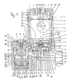
- the self-closing valve shown in the drawing is described below in a form in which it is suitable for use in sanitary facilities, that is to say for showers and similar devices for delivering mixed water of selectable temperature.
- the self-closing valve consists of a solid valve body 20, on which a lateral extension 65 is formed, and a sleeve-shaped housing 7, which has a laterally projecting extension 67 covering the extension 65 at the end facing the valve body 20.
- the housing 7 with extension 67 is attached to the valve body 20 in a manner not shown.
- a mixed water outlet connection 41 is formed on the valve body 20 opposite the extension 65. Between the mixed water outlet pipe 41 and the neck 65, an inlet pipe 43, 45 is provided on each side of the valve body 20.
- a cold runner 62 for cold water leads from the inlet port 43 into a mixing chamber 60 enclosed by the extension 65, into which a warm runner 64 for warm or hot water emanating from the inlet port 45 opens.
- the mixing chamber 60 communicates with an inlet channel 42 of the valve, which is connected via a valve chamber 44 to an outlet channel 46 opening into the outlet port 41 when the valve is open.
- the warm channel 64 opens into a lower annular chamber 69, which is peripherally sealed below the mixing chamber 60 by a cylindrical component 71 (annular seal 26).
- the cold channel 62 opens into an upper annular chamber 73, which is sealed peripherally against the mixing chamber by a further cylindrical component 75 and is formed between the mixing chamber 60 and the lower annular chamber 69.
- a mixing piston 23 is held axially displaceably within the cylinder component 71, an annular seal 25 sealing the sliding cylinder surfaces of the mixing piston 23 and the cylinder component 71 against penetrating water.
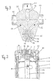
- the mixing piston 23 has a perforated plate 79 which is provided with a plurality of through openings and extends transversely to the axis of the mixing piston 23 and can be seen in plan view in FIG. 3.
- the through openings are arranged at the same distance from the axis of the mixing piston 23 and are equally spaced from one another and distributed around a central opening 81.
- a spring 83 is supported at one end on the bottom of the lower annular chamber 69 and presses against the underside of the perforated plate 79, so that the mixing piston 23 is acted upon by the spring 83 in its upper end position, which is caused by the upper end of the mixing piston 23 can be defined against a radially inwardly projecting ring 27 at the lower end of the further component 75, but is determined in a practical embodiment of the valve in a manner to be described.
- the mixing piston 23 is pressed by the spring 83 against a plunger 24, the lower conical end of which partially penetrates into the central opening 81 and bears against its upper boundary edge.
- the upper end opposite the lower conical end of the mixing piston 23 is held centrally in an axially movable control piston 32.
- the axial mobility of the control piston 32 is achieved by rotating it in a fine thread 84 which is provided in an axial bore of a holding part 31 which is fixedly connected to the projection 65 and in which a mating thread formed on the outer periphery of a lower section 85 of the control piston 32 engages.
- the control piston 32 is rotated in one direction on its head 74 in a manner to be described, this rotation leads to an axial downward movement of the control piston 32, which the plunger 24 follows.
- the plunger 24 therefore presses the mixing piston 23 down against the action of the spring 83.
- the control piston 32 on the head 74 is rotated in the opposite direction of rotation, the control piston 32 moves axially upward, with the result that the mixing piston 23 likewise moves axially upward.
- the mixing piston 23 is by a corresponding rotation of the control piston 32 between the mentioned upper end position and a lower one End position, which can be defined by abutting the lower end of the mixing piston 23 against the bottom of the lower annular chamber 69, axially adjustable.
- This adjustment which is made possible due to the fact that the axial length of the mixing piston 23 is significantly smaller than the distance between the lower surface of the ring 27 and the bottom of the lower annular chamber 69, makes an inlet cross-section 61 for the cold runner 62 and an inlet cross-section 63 changed for the hot runner 64.
- the inlet cross-section 61 is defined by the distance between the upper end of the mixing piston 23 and the underside of the ring 27, and the inlet cross-section 63 is defined by the distance between the lower end of the mixing piston 23 and the bottom of the lower annular chamber 69 below the inlet cross-section 61 is enlarged to an extent in which the inlet cross-section 63 is reduced.
- the mixing chamber 60 communicates with the warm channel 64 via the interior of the upper component 75 and the ring 27 and the openings in the perforated plate 79 with the inlet cross section 63, and with the inlet cross section 61 via the interior of the upper component 75 in fluid connection.
- annular seal 29 is interposed between the outer periphery of the lower portion 85 of the control piston 32 and the inner wall of the bore of the holding part 31, which keeps the space above the holding part 31 and within the extension 67 free of water.
- a further ring seal 30 is inserted between the holding part 31 and the extension 65.
- a first tooth segment 76 is formed on the radial periphery of the head 74, which is formed with a second tooth segment 56 at the lower end of a sleeve 54 to be explained.
- the second toothed segment 56 can also be formed in a manner not shown on a rotary knob, also not shown, which can be rotatably held in an opening 82 on the top of the extension 67.
- the second toothed segment 56 is formed at the lower end of a cylindrical sleeve 54, which is axially between a radially projecting ring flange 53 of an insert 10 firmly connected to the valve body 20 and a radially inwardly projecting shoulder 57 at the upper end of the housing 7 is immovable, but is rotatable.
- the bottom open and closed at the top with an end plate 4 sleeve 54 has in the end plate at least two eccentric, opposite through bores 58, 59, each of which is penetrated by a pin 51, 52 'firmly anchored in the head of the handle 1.
- a rotation of the handle 1 about its axis is therefore transmitted to the sleeve 54 by virtue of the pins 51, 52 and to the control piston 32 by virtue of the engagement of the two toothed segments 56, 76.
- this rotation of the control piston 32 can only take place within an angular range, approximately 180 °, determined by the stop pins. Therefore, the upper end position of the mixing piston 23 is determined by the contact of the head 74 with a first stop pin and the lower end position with the second stop pin.
- This rotation consequently leads to a change in the inlet cross-sections 61, 63, with the result that the temperature of the mixed water discharged from the valve can be selected continuously between the temperature of the cold water flowing in through the cold channel 62 and the hot water flowing through the warm channel 64, since that Mix the cold water and the warm water in the mixing chamber 60 and in the course of the further water flow through the inlet channel 42 and the valve chamber 44 completely.
- the temperature of the hot water brought in can be above that which the human body perceives as just tolerable or pleasant.
- the valve is equipped with a scalding protection as follows.
- the head 74 of the control piston 32 has an axial bore which has an internal thread in the upper part.
- a set screw 37 is screwed into the internal thread, against which an intermediate piece 36, which is displaceable in the bore and is sealed by means of ring seal 33 against water leakage, bears slidably from below.
- the upper end of the stamp 24 is caught in a blind hole open in the bottom in the intermediate piece 36.
- a rotation of the control piston 32 is followed by the adjusting screw 37, since this is normally held non-rotatably in the internal thread of the control piston bore by virtue of the pressure transmitted by the spring 83 via the plunger 24 and the intermediate piece 36.
- the set screw 37 can be rotated in the internal thread by means of a screwdriver, so that the plunger 24 is displaced downward relative to the control piston 32 by screwing in the set screw 37, which has the consequence that the axial adjustability range of the mixing piston caused by the rotation of the head 74 23 is shifted downward, that is to the disadvantage of the hot water portion of the mixed water, the inlet cross section 61 for cold water cannot fall below a minimum value. This ensures that at least a minimal amount of cold water is always added to the supplied hot water and thus the temperature of the mixed water dispensed cannot rise above the tolerance limit.
- the opening 82 is closed with a removable cap 35 and sealed by means of an annular seal 34, after which the head of the set screw 37 is accessible from the outside.
- the actuating mechanism for the valve diaphragm of the self-closing valve initially comprises a plate-shaped valve diaphragm 21, which is held in the valve body 20 at its edge and essentially closes off the valve chamber 44, with a central passage and an outer-center control nozzle 17.
- a closure part 40 with an axial pilot nozzle 19 which establishes a connection between the outlet duct 46 and a control chamber 47, which is delimited by the top of the valve membrane 21 and a valve cap 16 made of steel in the form of an inverted cup.
- a spring 15 is accommodated, on the lower, free end of which an armature disk 14 is fastened.
- the spring 15 presses the armature disk 14 from above onto the closure part 40, which presses the valve diaphragm 21 onto the valve seat 48, a middle shoulder of the closure part 40 sealingly penetrating into the opening of the outlet channel 46 and a middle stopper 55 the armature disk closes the pilot nozzle 19.
- the dynamic pressure of the water present in the inlet channel 42 is transmitted via the control nozzle 17 into the control chamber 47, so that the valve membrane 21 is only exposed to the closing pressure of the spring 15.
- the valve cap 16 is fastened in a sealing manner in the valve body 20 by means of an annular seal 22.
- a permanent magnetic ring 13 is fastened from below to a steel plate 49 covering the ring 13 in a manner not shown, which has a downwardly extending, central depression.
- a spring 12 which surrounds the depressions of the steel plate 49 and the valve cap 16, which is supported at one end on the valve cap 16 and presses the plate 49 with the ring 13 away from the valve cap 16 upwards.
- a peg-shaped spacer 97 which loosely extends through an opening in a lower leg 96 of a U-shaped bracket 92 which extends upwards.
- Another spring 11 is arranged between the lower end of the spacer 97, which is secured against falling out of the opening, and the underside of the lower leg 96.
- the lower leg 96 and the ring 13 are accommodated in an opening of the insert 10 so as to be axially movable.
- a timer in the form of a clockwork 8 is held on the insert 10 within the sleeve 54, which has an adjusting disc 9 on its front side shown in FIG Time span, in the example shown up to 120 seconds, during which the clockwork runs after being triggered. 2, in which the back of the clockwork is shown, the bracket 92 extends along the back of the timer 8 above it and has an upper leg 6 above the timer 8. The bracket 92 is screwed to a trigger 38 of the clockwork.
- actuating stamp 93 which is acted upon by a spring 3 housed in a central pocket 50 of the pusher 1, which is provided with an internal thread, against a lower stop of a screw plug 91 and downwards via the screw plug 91 protrudes.
- the screw plug 91 is screwed into the internal thread of the pocket 50 from below, drilled axially to accommodate the spring 3 and the actuating plunger 93 and provided with an annular flange 95 at the lower end.
- the thread-free central part of the screw plug 91 penetrates an axial, central opening in the end plate 4 in such a way that the ring flange 95 limits an axial movement of the lever 1 upwards by gripping the end plate 4.
- the head of the pusher 1 there is also a spiral spring 2, which presses on the outer surface of the end plate 4 and presses the pusher 1 into an end position (FIG. 2) remote from the end plate 4.
- the head of the pusher 1 is provided with a laterally extending apron which encompasses the upper part of the housing 7.
- An annular seal 5 between the apron and the part of the housing 7 which it encompasses prevents the ingress of dust and other impurities into the valve.
- the pusher 1 is pressed axially downward from the raised rest position shown in FIG. 2. This movement is followed by the actuating ram 93, which moves the bracket 92 axially downward, so that the trigger 38 carried by the bracket 92 triggers the timer 8.
- the downward movement of the bracket 92 leads via the spacer 97 to a downward movement of the permanent magnetic ring 13, which comes to rest on the upper side of the valve cap 16. Is the ring 13 on the valve cap 16, its magnetic field pulls the armature plate 14 from the Valve diaphragm 21 or the closure part 40 against the action of the spring 15 from to the lower contact with the valve cap 16.
- the plug 55 releases the pilot nozzle 19, so that the water pressure in the control chamber 47 results decreases that the valve membrane 21 lifts off from the valve seat 48 together with the closure part 40 under the effect of the dynamic pressure of the water present in the inlet channel 42 and thus opens the valve.
- the diameter of the pilot nozzle 19 is larger than that of the control nozzle 17.
- the trigger 38 may go up slightly during the running of the timer 8, a movement which must not lead to the magnetic ring 13 being lifted off the valve cap 16.
- the spring 11 is used, which allows a slight upward movement of the bracket 92 with the trigger 38 without the ring magnet 13 lifting off the valve cap 16. Only when the preset period of time of the timer 8 has elapsed does the trigger 38 return to its rest position shown in FIG. 2 over a substantial distance, taking the bracket 92 with it. The spring 11 is relaxed so far that the ring magnet 13 reliably lifts off the valve cap 16 under the action of the spring 12.
- the lifting of the ring magnet 13 leads to a reduction in the magnetic attraction force of the armature plate 14 with the result that the spring 15 presses the armature plate 14 onto the valve diaphragm 21 with the closure part 40 in the depression of the valve cap 16 and thus closes the valve.
- the ram 24 is modified by a thermostat 39 in a modification of the valve described above replaced, the head of which is screwed into the blind hole opposite the set screw in the intermediate piece 36 of the control piston 32 and the foot of which is fastened in a cylindrical component 66.
- the mixing piston 23 presses against the underside of the component 66 due to the spring 83.
- the thermostat 39 contains a medium which contracts when it cools down and thereby shortens the axial length of the thermostat 39 and which expands when heated and thereby the axial length of the thermostat 39 enlarged.
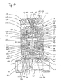
- the self-closing valve shown in FIG. 4 differs from that shown in FIG. 1 essentially in that, instead of the clockwork 8, a hydraulic module 108 is installed, which almost completely fills up a cylindrical housing 107 radially.
- the hydraulic module 108 has an upper part 123 drilled out in the middle, an intermediate plate 125 and a lower part 127, which are screwed together in radial alignment by means of a plurality of bolts 124 and have the same radial dimensions.
- the upper part 123 has a central through opening 126 in its ceiling section.
- a first bendable membrane 162 is clamped between the upper part 123 and the intermediate plate 125, the peripheral edge thickening 163 of which is anchored in an annular groove of the upper part 123.
- the membrane 162 initially nestles against the inner wall of the bore 129 of the upper part 123 and is turned inwards in the middle in such a way that it can rest against the lower outer surface of a stopper-shaped trigger 138.
- the peripheral edge of a second membrane 164 is clamped between the intermediate plate 125 and the lower part 127, the peripheral edge thickening 165 of which is captured in an annular groove of the lower part 127.
- the second membrane nestles towards the center 164 to the inner surface of a cylindrical bore 131 of the lower part 127 and is turned upwards in the middle in such a way that it can rest against the upper outer surface of a T-shaped plunger 196.
- the plunger 196 has a shaft 198 which extends downward centrally from its head 197 and which penetrates downward through a central through opening in the lower part 127.
- the shaft 198 is surrounded by a spiral spring 111, which grips the head 197 and is supported on the bottom 132 of a radial widening of the central passage opening in the lower part 127.
- the intermediate plate has a deep, ring-shaped, axial, central cut 133 extending from its underside facing the lower part 127, which leaves a central cup 134, which is formed by a cylindrical bore from the top of the intermediate plate.
- a central cup 134 which is formed by a cylindrical bore from the top of the intermediate plate.
- an axial nozzle 160 of small diameter is introduced in the center, which connects the interior of the cup 134 with the space formed below the intermediate plate 125.
- Radial, downward bores 137, 139 are provided in the cylindrical side wall of the cup-shaped middle piece 134, the respective diameter of which is considerably larger, expediently a multiple of the diameter of the nozzle 160.
- a blind hole 151 is also drilled into the intermediate plate 125 from its cylindrical outer surface, which is connected behind a filling valve via a branch channel 154 to the upper side of the intermediate plate facing the upper part 123.
- the first membrane 162 encloses with the upper side of the intermediate plate 125 and the interior of the cup-shaped middle part 134 of the intermediate plate 125 a first chamber 156, which is filled with oil via the filling valve 152.
- the bores 137, 139, 143 form, together with the sleeve 145, a type of check valve which passes through when the chamber 156 is compressed Pushing the trigger 138 inward allows oil to flow out into a second chamber 158 which is enclosed by the mentioned cut 133 in the intermediate plate 125 and the second membrane 164.
- a return flow of oil from the second chamber 158 through the bores 137, 139, 143 is not possible since these remain closed by the sleeve 145.
- the oil return flow from the second chamber 158 into the first chamber 156 is rather only possible via the nozzle 160.
- the valve according to FIG. 4 also has a permanent magnetic ring 113 which is glued to an annular surface of a guide part 149 from below.
- the guide part 149 has on the upper side opposite the ring 113 guide tracks 174, 176, into which displacement bodies 170, 172 can run and remain trapped.
- Each guideway 174, 176 is adapted in its course to the diameter of the shaft 198 such that the end of each guideway 174, 176 near the ring 113 is so far from the axial center line of the shaft 198 that the shaft 198 is freely between the balls 170, 172 to move to the ring 113, which allows a corresponding central cutout 177 of the guide part 149.
- each guideway 174, 176 extends away from the ring 113 and towards the center line of the shaft 198, that is to say radially inwards, so that when the shaft 198 moves away from the ring 113 with a sufficient further movement and a corresponding upward movement of the ring 113 with the guide part 149, the balls 170, 172 move radially inwards in their guide tracks 174, 176 and thereby increasingly underscore the underside of the shaft 198 which is bevelled at the edge.
- the balls 170, 172 are forced by inclined, radially inwardly directed guide surfaces 175 on the underside of the lower part 127 during the upward movement of the guide part 149, against which the balls 170, 172 run.
- the permanent magnetic ring 113 thus surrounds a spring 112 which is supported on the upper side of a valve cap 116 and presses against the lower side of the guide part 149.
- the valve cap 116 has a depression which extends into the spring 112 and in which a spring 115 with an armature disk 114 is seated, the latter having a central stopper.
- the valve cap 116 together with the valve membrane 121, encloses a control chamber in which a closure part 140 is held so as to be axially movable. Closure part 140 with valve membrane 121 can close off a valve chamber 144, which is formed between an inlet channel 142 and an outlet channel 146 in the valve body 120.
- the control chamber 147 is connected to the valve chamber 144 via a control nozzle 117 which penetrates the valve membrane 121.
- the valve cap 116 is held on the valve body 120 by means of a ring 178 fastened to the valve body 120 and laterally surrounding the valve cap 116, the upper collar 180, which projects beyond the valve cap 116 and surrounds the permanent magnetic ring 113 with a radial spacing, is provided with an external thread.
- An insert ring 110 is screwed onto the outside of the collar 180, which laterally surrounds the guide part 149 and ends at the top with an annular bearing surface 186.
- the timer 108 is placed on the bearing surface 186 so that the lower part 127 rests on the bearing surface 186. 4, an upper internal thread adjoins the bearing surface 186, into which the timer 108 can be screwed by means of an apron 187 provided with an external thread.
- the insert ring 110 has a radially outward-pointing ring flange 153 with a radially inwardly offset, adjacent external thread, onto which the cylindrical jacket 106 of a valve housing 107 is screwed.
- a pusher 101 is seated in a central recess on the upper side of the housing 107 and is underpinned by a spring 102 and acted upon outwards.
- An axially pierced screw plug 191 which is penetrated by an actuating plunger 193, is screwed in from below into an internally threaded tubular socket 118, which is formed centrally on the pusher 101 and which penetrates a central through bore of the pusher 101.
- the actuating stamp is acted upon by a spring 103 accommodated in the connecting piece 118 and can bear with an annular shoulder on an inner surface of the actuating stamp 193.
- the shaft 166 of the trigger 138 is axially guided and displaceable in a central through hole in the upper part 123.
- the pusher 101 is pressed against the action of the spring 102 until its apron stops on the bottom of the recess in the housing 107.
- the screw plug 191 in turn presses the trigger 138 via the adjusting screw 109 into the first chamber 156, so that oil is transferred from the first chamber 156 through the bores 135, 139, 143 into the second chamber 158 and the plunger 196 against the action of the spring 111 yourself down emotional.
- the shaft 198 drives the balls 170, 172 apart, which move downward on the guide surfaces 175 and press the guide part 149 with the ring magnet 113 onto the valve cap 116.
- the armature plate 114 is lifted off the closure part 140, so that the valve membrane 121 opens the valve.
- the spring 111 drives the plunger 196 upwards, since the excess oil in the second chamber 158 can flow back into the first chamber 156 through the narrow nozzle 160 which limits the return flow and thereby moves the trigger 138 upwards.
- the trigger 101 has now returned to its initial position, not shown, so that the trigger 138 with the adjusting screw 109 finds a free escape path upwards.
- the balls 170, 172 again assume their radially inner position, into which they are urged by the ring magnet 113 with the guide part 149, which gradually lifts off from the valve cap 116 under the action of the spring 112. If the ring magnet 113 is sufficiently far away from the valve cap 116, the armature plate 114 drops again and closes the valve.
- the opening time of the valve is thus determined by the return flow of the oil from the second chamber 158 through the nozzle 160 into the first chamber 156.
- the amount of this oil portion can be changed by adjusting the adjusting screw 109 relative to the trigger 138. If the connecting screw 109 is screwed very far into the trigger 138, more oil is contained in the first chamber 156, so that a larger amount of oil is transferred into the second chamber 158 when the valve is opened. After opening the valve, the shaft 198 can move down freely between the balls 170, 172 between them without the opening of the valve being influenced thereby. Due to the backflow of the larger amount of oil from the second chamber 158 through the nozzle 160, however, the valve remains open for a correspondingly longer time and then closes automatically as described.
- the valve body 120 can also be provided with an extension corresponding to the extension 67 for receiving a mixing valve attachment, as has been described for the valve with reference to FIG. 1. Therefore, for example, the valve according to FIGS. 1 to 3 can be equipped with the hydraulic module 108 instead of the clockwork 8 shown there, only the steel plate 49 (with ring magnet 13) through the guide part 149 (with ring magnet 113) and associated balls 170, 172 and the housing 107 would be replaced by the housing 7 with sleeve 54. Therefore, the timer is an interchangeable module, for which either a clockwork 8 or the hydraulic module 108 can be used.
Landscapes
- Engineering & Computer Science (AREA)
- General Engineering & Computer Science (AREA)
- Mechanical Engineering (AREA)
- Multiple-Way Valves (AREA)
- Temperature-Responsive Valves (AREA)
- Self-Closing Valves And Venting Or Aerating Valves (AREA)
- Mechanically-Actuated Valves (AREA)
- Water Treatment By Sorption (AREA)
- Separation Using Semi-Permeable Membranes (AREA)
Priority Applications (1)
| Application Number | Priority Date | Filing Date | Title |
|---|---|---|---|
| AT89101119T ATE103681T1 (de) | 1988-01-23 | 1989-01-23 | Selbstschlusszeitventil, vorzugsweise fuer wasser. |
Applications Claiming Priority (2)
| Application Number | Priority Date | Filing Date | Title |
|---|---|---|---|
| DE3801936 | 1988-01-23 | ||
| DE3801936A DE3801936A1 (de) | 1988-01-23 | 1988-01-23 | Selbstschlussventil vorzugsweise fuer wasser |
Publications (3)
| Publication Number | Publication Date |
|---|---|
| EP0326058A2 true EP0326058A2 (fr) | 1989-08-02 |
| EP0326058A3 EP0326058A3 (en) | 1990-06-27 |
| EP0326058B1 EP0326058B1 (fr) | 1994-03-30 |
Family
ID=6345853
Family Applications (1)
| Application Number | Title | Priority Date | Filing Date |
|---|---|---|---|
| EP89101119A Expired - Lifetime EP0326058B1 (fr) | 1988-01-23 | 1989-01-23 | Clapet à fermeture automatique spécialement pour l'eau |
Country Status (3)
| Country | Link |
|---|---|
| EP (1) | EP0326058B1 (fr) |
| AT (1) | ATE103681T1 (fr) |
| DE (3) | DE3801936A1 (fr) |
Cited By (1)
| Publication number | Priority date | Publication date | Assignee | Title |
|---|---|---|---|---|
| WO2018130709A1 (fr) * | 2017-01-16 | 2018-07-19 | Grohe Ag | Soupape pour corps encastré de robinetterie sanitaire munie d'un bouton de manœuvre fixé rotatif à un bouton de soupape |
Family Cites Families (7)
| Publication number | Priority date | Publication date | Assignee | Title |
|---|---|---|---|---|
| CH588658A5 (fr) * | 1974-02-18 | 1977-06-15 | Huba Control Ag | |
| DE3109943A1 (de) * | 1981-03-14 | 1982-10-07 | Rotter GmbH & Co KG, 1000 Berlin | Permanentmagnetisch gesteuertes selbstschlussventil |
| DE3409509A1 (de) * | 1984-03-15 | 1985-09-19 | Meloh-Armaturen GmbH, 5860 Iserlohn | Selbstschliessendes absperrventil mit zeitschaltwerk |
| DE3409673A1 (de) * | 1984-03-16 | 1985-09-19 | Friedrich 3300 Braunschweig Gries | Schnellschlussventil mit mebrangesteuertem dauermagnet |
| DE3432731A1 (de) * | 1984-09-06 | 1986-03-13 | Hansa Metallwerke Ag | Thermostatisch gesteuerte unterputzarmatur |
| DE3432730A1 (de) * | 1984-09-06 | 1986-03-06 | Hansa Metallwerke Ag, 7000 Stuttgart | Thermostatisch gesteuerte mischbatterie |
| FI854159L (fi) * | 1984-11-15 | 1986-05-16 | Grohe Armaturen Friedrich | Regleringsanordning foer ifyllningsmaengden. |
-
1988
- 1988-01-23 DE DE3801936A patent/DE3801936A1/de active Granted
- 1988-01-23 DE DE8816601U patent/DE8816601U1/de not_active Expired - Lifetime
-
1989
- 1989-01-23 AT AT89101119T patent/ATE103681T1/de not_active IP Right Cessation
- 1989-01-23 EP EP89101119A patent/EP0326058B1/fr not_active Expired - Lifetime
- 1989-01-23 DE DE89101119T patent/DE58907310D1/de not_active Expired - Fee Related
Cited By (4)
| Publication number | Priority date | Publication date | Assignee | Title |
|---|---|---|---|---|
| WO2018130709A1 (fr) * | 2017-01-16 | 2018-07-19 | Grohe Ag | Soupape pour corps encastré de robinetterie sanitaire munie d'un bouton de manœuvre fixé rotatif à un bouton de soupape |
| CN110573778A (zh) * | 2017-01-16 | 2019-12-13 | 高仪股份公司 | 用于洁具配件的暗线安装体的、具有可旋转地固定至阀旋钮按的控制旋钮的阀 |
| CN110573778B (zh) * | 2017-01-16 | 2021-05-04 | 高仪股份公司 | 用于洁具配件的暗线安装体的、具有可旋转地固定至阀旋钮按的控制旋钮的阀 |
| US11105438B2 (en) | 2017-01-16 | 2021-08-31 | Grohe Ag | Valve for a flush-mounted body of a sanitary fitting, having a control knob rotatably fastened to a valve knob |
Also Published As
| Publication number | Publication date |
|---|---|
| DE58907310D1 (de) | 1994-05-05 |
| EP0326058B1 (fr) | 1994-03-30 |
| EP0326058A3 (en) | 1990-06-27 |
| DE3801936C2 (fr) | 1991-05-23 |
| ATE103681T1 (de) | 1994-04-15 |
| DE3801936A1 (de) | 1989-08-03 |
| DE8816601U1 (de) | 1990-02-15 |
Similar Documents
| Publication | Publication Date | Title |
|---|---|---|
| EP0264361B1 (fr) | Vanne à fermeture automatique pour installations sanitaires | |
| DE2056072A1 (de) | Thermostatisch gesteuertes Mischventil fur Warm und Kaltwasser | |
| DE2739196A1 (de) | Umschaltventil | |
| DE4341650A1 (de) | Selbstschlußventil | |
| DE3690557C2 (fr) | ||
| EP3748207A1 (fr) | Cartouche de soupape pour une armature sanitaire | |
| DE4224389B4 (de) | Ventil mit T-förmigem bzw. N-förmigem, wippenartigem Ventilglied | |
| EP0326058B1 (fr) | Clapet à fermeture automatique spécialement pour l'eau | |
| EP3792534B1 (fr) | Dispositif de soupape à fermeture automatique | |
| EP0359999A1 (fr) | Mitigeur | |
| DE3615688A1 (de) | Laengenverstellbare gasfeder und betaetigungseinrichtung hierfuer | |
| DE19923988C2 (de) | Sanitäre Selbstschlußarmatur | |
| DE2008290C3 (de) | Reduzierventil mit einer Sicherheitseinrichtung und Handbetätigung fur die Fluidabsperrung | |
| DE1550412C3 (de) | Mischventil mit einer Sicherheitseinrichtung gegen Verbrühen | |
| DE2416286A1 (de) | Selbstschliessende armatur | |
| DE2852006C2 (de) | Selbstschlußarmatur | |
| DE3046084C2 (fr) | ||
| DE1962026C3 (de) | Mischventil | |
| DE4105166A1 (de) | Ventilvorrichtung | |
| DE8801009U1 (de) | Selbstschlußventil vorzugsweise für Wasser | |
| EP1039189B1 (fr) | Dispositif de commande d'un organe de commutation | |
| DE8701593U1 (de) | Thermostatisches Ventil | |
| DE2625601A1 (de) | Betaetigungsvorrichtung fuer den rueckstauverschluss eines kellerablaufs oder fuer dergleichen versenkt eingebauter absperrorgane | |
| DE10202560A1 (de) | Thermostat-Mischventil | |
| DE3109943A1 (de) | Permanentmagnetisch gesteuertes selbstschlussventil |
Legal Events
| Date | Code | Title | Description |
|---|---|---|---|
| PUAI | Public reference made under article 153(3) epc to a published international application that has entered the european phase |
Free format text: ORIGINAL CODE: 0009012 |
|
| AK | Designated contracting states |
Kind code of ref document: A2 Designated state(s): AT BE DE FR GB IT |
|
| PUAL | Search report despatched |
Free format text: ORIGINAL CODE: 0009013 |
|
| AK | Designated contracting states |
Kind code of ref document: A3 Designated state(s): AT BE DE FR GB IT |
|
| 17P | Request for examination filed |
Effective date: 19901217 |
|
| 17Q | First examination report despatched |
Effective date: 19920723 |
|
| GRAA | (expected) grant |
Free format text: ORIGINAL CODE: 0009210 |
|
| AK | Designated contracting states |
Kind code of ref document: B1 Designated state(s): AT BE DE FR GB IT |
|
| REF | Corresponds to: |
Ref document number: 103681 Country of ref document: AT Date of ref document: 19940415 Kind code of ref document: T |
|
| REF | Corresponds to: |
Ref document number: 58907310 Country of ref document: DE Date of ref document: 19940505 |
|
| GBT | Gb: translation of ep patent filed (gb section 77(6)(a)/1977) |
Effective date: 19940413 |
|
| ITF | It: translation for a ep patent filed | ||
| ET | Fr: translation filed | ||
| PLBE | No opposition filed within time limit |
Free format text: ORIGINAL CODE: 0009261 |
|
| STAA | Information on the status of an ep patent application or granted ep patent |
Free format text: STATUS: NO OPPOSITION FILED WITHIN TIME LIMIT |
|
| 26N | No opposition filed | ||
| PGFP | Annual fee paid to national office [announced via postgrant information from national office to epo] |
Ref country code: GB Payment date: 19990105 Year of fee payment: 11 |
|
| PGFP | Annual fee paid to national office [announced via postgrant information from national office to epo] |
Ref country code: FR Payment date: 19990118 Year of fee payment: 11 |
|
| PGFP | Annual fee paid to national office [announced via postgrant information from national office to epo] |
Ref country code: BE Payment date: 19990121 Year of fee payment: 11 Ref country code: AT Payment date: 19990121 Year of fee payment: 11 |
|
| PG25 | Lapsed in a contracting state [announced via postgrant information from national office to epo] |
Ref country code: GB Free format text: LAPSE BECAUSE OF NON-PAYMENT OF DUE FEES Effective date: 20000123 Ref country code: AT Free format text: LAPSE BECAUSE OF NON-PAYMENT OF DUE FEES Effective date: 20000123 |
|
| PG25 | Lapsed in a contracting state [announced via postgrant information from national office to epo] |
Ref country code: BE Free format text: LAPSE BECAUSE OF NON-PAYMENT OF DUE FEES Effective date: 20000131 |
|
| BERE | Be: lapsed |
Owner name: R. UND D. ROTTER G.M.B.H. MED-CHEM.APPARATE- UND Effective date: 20000131 |
|
| GBPC | Gb: european patent ceased through non-payment of renewal fee |
Effective date: 20000123 |
|
| PG25 | Lapsed in a contracting state [announced via postgrant information from national office to epo] |
Ref country code: FR Free format text: LAPSE BECAUSE OF NON-PAYMENT OF DUE FEES Effective date: 20000929 |
|
| REG | Reference to a national code |
Ref country code: FR Ref legal event code: ST |
|
| PGFP | Annual fee paid to national office [announced via postgrant information from national office to epo] |
Ref country code: DE Payment date: 20001229 Year of fee payment: 13 |
|
| PG25 | Lapsed in a contracting state [announced via postgrant information from national office to epo] |
Ref country code: DE Free format text: LAPSE BECAUSE OF NON-PAYMENT OF DUE FEES Effective date: 20020801 |
|
| PG25 | Lapsed in a contracting state [announced via postgrant information from national office to epo] |
Ref country code: IT Free format text: LAPSE BECAUSE OF NON-PAYMENT OF DUE FEES;WARNING: LAPSES OF ITALIAN PATENTS WITH EFFECTIVE DATE BEFORE 2007 MAY HAVE OCCURRED AT ANY TIME BEFORE 2007. THE CORRECT EFFECTIVE DATE MAY BE DIFFERENT FROM THE ONE RECORDED. Effective date: 20050123 |