EP0326085A2 - Production of nozzle member - Google Patents
Production of nozzle member Download PDFInfo
- Publication number
- EP0326085A2 EP0326085A2 EP89101206A EP89101206A EP0326085A2 EP 0326085 A2 EP0326085 A2 EP 0326085A2 EP 89101206 A EP89101206 A EP 89101206A EP 89101206 A EP89101206 A EP 89101206A EP 0326085 A2 EP0326085 A2 EP 0326085A2
- Authority
- EP
- European Patent Office
- Prior art keywords
- nozzle member
- pipe stock
- stock
- producing
- inner diameter
- Prior art date
- Legal status (The legal status is an assumption and is not a legal conclusion. Google has not performed a legal analysis and makes no representation as to the accuracy of the status listed.)
- Granted
Links
Images
Classifications
-
- B—PERFORMING OPERATIONS; TRANSPORTING
- B22—CASTING; POWDER METALLURGY
- B22D—CASTING OF METALS; CASTING OF OTHER SUBSTANCES BY THE SAME PROCESSES OR DEVICES
- B22D37/00—Controlling or regulating the pouring of molten metal from a casting melt-holding vessel
-
- B—PERFORMING OPERATIONS; TRANSPORTING
- B21—MECHANICAL METAL-WORKING WITHOUT ESSENTIALLY REMOVING MATERIAL; PUNCHING METAL
- B21C—MANUFACTURE OF METAL SHEETS, WIRE, RODS, TUBES, PROFILES OR LIKE SEMI-MANUFACTURED PRODUCTS OTHERWISE THAN BY ROLLING; AUXILIARY OPERATIONS USED IN CONNECTION WITH METAL-WORKING WITHOUT ESSENTIALLY REMOVING MATERIAL
- B21C37/00—Manufacture of metal sheets, rods, wire, tubes, profiles or like semi-manufactured products, not otherwise provided for; Manufacture of tubes of special shape
- B21C37/06—Manufacture of metal sheets, rods, wire, tubes, profiles or like semi-manufactured products, not otherwise provided for; Manufacture of tubes of special shape of tubes or metal hoses; Combined procedures for making tubes, e.g. for making multi-wall tubes
- B21C37/15—Making tubes of special shape; Making tube fittings
- B21C37/16—Making tubes with varying diameter in longitudinal direction
-
- B—PERFORMING OPERATIONS; TRANSPORTING
- B21—MECHANICAL METAL-WORKING WITHOUT ESSENTIALLY REMOVING MATERIAL; PUNCHING METAL
- B21K—MAKING FORGED OR PRESSED METAL PRODUCTS, e.g. HORSE-SHOES, RIVETS, BOLTS OR WHEELS
- B21K21/00—Making hollow articles not covered by a single preceding sub-group
- B21K21/08—Shaping hollow articles with different cross-section in longitudinal direction, e.g. nozzles, spark-plugs
-
- Y—GENERAL TAGGING OF NEW TECHNOLOGICAL DEVELOPMENTS; GENERAL TAGGING OF CROSS-SECTIONAL TECHNOLOGIES SPANNING OVER SEVERAL SECTIONS OF THE IPC; TECHNICAL SUBJECTS COVERED BY FORMER USPC CROSS-REFERENCE ART COLLECTIONS [XRACs] AND DIGESTS
- Y10—TECHNICAL SUBJECTS COVERED BY FORMER USPC
- Y10T—TECHNICAL SUBJECTS COVERED BY FORMER US CLASSIFICATION
- Y10T29/00—Metal working
- Y10T29/49—Method of mechanical manufacture
- Y10T29/49428—Gas and water specific plumbing component making
- Y10T29/49432—Nozzle making
-
- Y—GENERAL TAGGING OF NEW TECHNOLOGICAL DEVELOPMENTS; GENERAL TAGGING OF CROSS-SECTIONAL TECHNOLOGIES SPANNING OVER SEVERAL SECTIONS OF THE IPC; TECHNICAL SUBJECTS COVERED BY FORMER USPC CROSS-REFERENCE ART COLLECTIONS [XRACs] AND DIGESTS
- Y10—TECHNICAL SUBJECTS COVERED BY FORMER USPC
- Y10T—TECHNICAL SUBJECTS COVERED BY FORMER US CLASSIFICATION
- Y10T29/00—Metal working
- Y10T29/49—Method of mechanical manufacture
- Y10T29/49789—Obtaining plural product pieces from unitary workpiece
- Y10T29/49794—Dividing on common outline
Definitions
- This invention relates to a process of production of a nozzle member of a small diameter having a inside tapered or stepped dispersing portion which is difficult to work.
- nozzle members in order to increase the speed of movement of a yarn string to be handled and minimize air consumption required for it.
- a dispersing portion of a nozzle member for a throat portion to an air exit is formed such that the diameter thereof is increased in a gentle linear taper or in several steps or else has an expanded portion formed intermediately thereof.
- Employment of any of such structures as described just above can prevent appearance of unnecessary impulse waves in an air flow within the nozzle and maintain an accelerating action of the air flow.
- Such a structure is disclosed, for example, in U.S. Patent No. 4,550,752 and Japanese Patent Laid-Open No. 56-68137.
- a metal material As a material for a pipe stock from which a nozzle member is to be formed, a metal material is used which has a ductility that satisfies an area decreasing rate required in drawing but does not yield a crack or the like.
- An exemplary one of such materials is an austenitic stainless steel such as SUS304L.
- L H is a grip length of a portion of the pipe stock 1 which is to be gripped by a holding tool 10
- L d is a suitable cutting margin
- two nozzle members of the same configuration are produced from a single stock.
- Such a pipe stock 1 as described above is machined at an outside thereof into such a profile as shown in Fig. 1(B) by mechanical machining.
- the portion of the pipe stock 1 within the grip length L H is finished into an outer diameter D1 while other portions within the ranges of the length L0 are finished into a linear taper profile such that they may have a thickness of material corresponding to the inside configuration of a nozzle member to be produced.
- the portion of the pipe stock 1 within the grip length L H is gripped by the holding tool 10 as shown in Fig. 1(C), and the pipe stock 1 is drawn in the direction indicated by an arrow mark by means of a die 20 which has an inner diameter equal to D1.
- the die 20 used here may be of any known type such as a sintered alloy die.
- the lubricant for drawing may be any of a dry type lubricant and a wet type lubricant.
- the pipe stock 1 is formed to have an outer diameter equal to D1 over the overall length thereof while an outwardly projected portion of the pipe stock 1 is expanded inwardly so that the inner bore of the pipe stock 1 after completion of drawing is contracted substantially in an axial symmetrical relationship to the outer profile of the linear taper of the pipe stock 1 before drawing.
- the length of each of the drawn portions of the pipe stock 1 which has been formed into the inside linear tapers is equal to the length L1 which coincides with the preset length of a nozzle member 2 to be produced while the inner diameters of the opposite end portions of each of the drawn portions of the pipe stock 1 which have the length L1 present the maximum inner diameter d1 and the minimum diameter d2 of a nozzle member to be produced because the thicknesses of material t01 and t02 at the opposite end portions are maintained invariably. Then, if the pipe stock 1 is cut at the opposite ends of the portions thereof having the length L1, a pair of nozzle members 2 having a predetermined configuration are obtained as shown in Fig. 1(E). As shown in Fig.
- the elongation percentage ⁇ upon drawing generally increases in a proportional relationship to the area decreasing rate R.
- an elongation percentage ⁇ is estimated in advance or found out in advance through an experiment, and the length L0 of the stock is reduced by an extent corresponding to the elongation percentage ⁇ .
- nozzle members of various inside profiles can be produced according to the present invention.
- another nozzle member which has a throat portion 3 and a plurality of stepped portions 4a and 4b as shown in Fig. 4(B) and a further nozzle member which has a plurality of stepped portions 4a, 4b, ... and has an expanded portion 5 of a greater diameter at an intermediate portion thereof as shown in Fig. 5(B) can be produced in a similar manner to the embodiment described hereinabove with reference to Figs. 1(A) to 1(E).
- FIG. 3(A), 4(A) and 5(A) show configurations of the pipe stocks 1 before drawing from which the nozzle members 2 shown in Figs. 3(B), 4(B) and 5(B) are to be produced, respectively.
- an arrow mark indicates the drawing direction of a pipe stock 1 and the dimension D1 indicated by two-dot chain lines denotes a bore size of a die 20 to be used while the dimension d1 denotes a maximum inner diameter of a nozzle member 2.
- the inner diameter d0 of a pipe stock 1 after working for an outside profile must necessarily be equal to or greater than the maximum inner diameter d1 of a nozzle member 2 to be produced, and the pipe stock 1 from which such a nozzle member 2 is to be produced must necessarily have an outer diameter equal to the inner diameter d0 to which twice the maximum thickness of material of the nozzle member 2 is added.
- the bore size of the die 20 should be equal to an outer diameter of a nozzle member 2 to be produced where further finishing of an outside peripheral face of the nozzle member 2 is not taken into consideration, but where there is the necessity of such further finishing, an amount of finish should be added to set the bore size of the die 20 a little greater than an outer diameter of a nozzle member 2.
- a pipe stock is shaped such that an outside profile thereof may appear in an axial symmetrical relationship on an inside profile thereof
- a nozzle member which is too complicated in inside profile to work the same by wire cutting electric discharge machining or by mechanical machining can be produced readily as a single part with a high degree of accuracy.
- the roughness of inner and outer surfaces of the pipe stock after working for the outside profile was about 8 S (JIS B0601), but the roughness of the inner surface after drawing was about 10 S.
- the inner surface was subject to abrasive grain fluid polishing. As a result, about 3 S of the roughness of the inner surface was obtained.
- the invention provides a process of producing a nozzle member as a single part having an inner diameter which varies along an axial direction of the nozzle member.
- the process comprises the step of drawing a pipe stock having a predetermined outside profile so as to transfer the outside profile in an axial symmetrical relationship to an inside profile of the pipe stock.
Landscapes
- Engineering & Computer Science (AREA)
- Mechanical Engineering (AREA)
- Metal Extraction Processes (AREA)
- Looms (AREA)
Abstract
Description
- This invention relates to a process of production of a nozzle member of a small diameter having a inside tapered or stepped dispersing portion which is difficult to work.
- In the field of textile machines, a technique of sucking or transporting a yarn string by means of an air flow is used universally, and various types of nozzle members are used for the technique.
- Various proposals have been made to such nozzle members in order to increase the speed of movement of a yarn string to be handled and minimize air consumption required for it. Typically, a dispersing portion of a nozzle member for a throat portion to an air exit is formed such that the diameter thereof is increased in a gentle linear taper or in several steps or else has an expanded portion formed intermediately thereof. Employment of any of such structures as described just above can prevent appearance of unnecessary impulse waves in an air flow within the nozzle and maintain an accelerating action of the air flow. Such a structure is disclosed, for example, in U.S. Patent No. 4,550,752 and Japanese Patent Laid-Open No. 56-68137.
- Generally, long-size pipe stocks which have a uniform inner diameter and are high in accuracy in dimension can be conventionally obtained readily as drawn stocks or extruded materials. However, generally it is very difficult to produce a nozzle member having such a special inside profile as a single part because of the facts that the axial length thereof is extremely great while the inner diameter is small and so on. Therefore, conventional processes of producing such a nozzle member commonly include steps of working a plurality of divided parts of a suitable length unit for the nozzle member by means suitable for working for a small diameter such as, for example, wire cutting electric discharge machining and then assembling the divided parts into a unitary member.
- With such a conventional technique as described above, however, a nozzle member cannot be produced as a single part. Accordingly, there are problems that the production cost is very high and that it is difficult to realise a predetermined degree of accuracy of products. Further, wire cutting electric discharge machining has another problem that, since a wire is curved like a catenary as the working length is increased, it is difficult to attain a worked face of an accurate linear taper.
- It is an object of the present invention to provide a process of producing a nozzle member by which a nozzle member having an arbitrary inside profile can be readily produced as a single part of a high degree of accuracy.
- The above and other objects, features and advantages of the present invention will become apparent from the following description and the appended claims, taken in conjunction with the accompanying drawings.
-
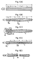
- Figs. 1(A) to 1(E) illustrate different steps of a process of producing a nozzle member according to the present invention, Fig. 1(A) being a sectional view of a pipe stock to be worked, Fig. 1(B) being a side elevational view, partly in section, of the pipe stock after an outer periphery thereof is machined, Fig. 1(C) being a side elevational view, partly in section, of the pipe stock before drawing, Fig. 1(D) a sectional view of the pipe stock after drawing, and Fig. 1(E) being a sectional view of the nozzle member after the process is completed
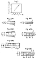
- Fig. 2 is a graph illustrating a relationship between an area decreasing rate and an elongation percentage of a pipe stock in a drawing step; and
- Figs. 3(A) and 3(B), Figs. 4(A) and 4(B) and Figs. 5(A) and 5(B) illustrate different embodiments of the present invention, Figs. 3(A), 4(A) and 5(A) being side elevational views, partly in section, of pipe stocks before drawing, and Figs. 3(B), 4(B) and 5(B) being sectional views of nozzle members after drawing.
- As a material for a pipe stock from which a nozzle member is to be formed, a metal material is used which has a ductility that satisfies an area decreasing rate required in drawing but does not yield a crack or the like.
- It is to be noted that the area decreasing rate R is defined by
R = (D₀² - D₁²)/D₀²
where D₀ is an outer diameter of a pipe stock before drawing and D₁ is an outer diameter of the pipe stock after drawing. - An exemplary one of such materials is an austenitic stainless steel such as SUS304L.
- In the following, shaping of such a
nozzle member 2 which has an outer diameter D₁ and a length L₁ and has an inside profile of a linear taper the inner diameter of which is d₁ at the greater diameter side and d₂ at the smaller diameter side as shown in Fig. 1(E) will be described in detail. - At first, such a pipe stock 1 which has an outer diameter D₀, an inner diameter d₀ and a length L = 2L₀ + LH + Ld as shown in Fig. 1(A) is prepared as a stock. Here, LH is a grip length of a portion of the pipe stock 1 which is to be gripped by a holding
tool 10, Ld is a suitable cutting margin, and L₀ (represented by L₀ = L₁/α, where α is an elongation percentage in drawing and α > 1) is a length of a stock to make a nozzle member, and it is assumed that d₀ = d₁ and D₀ ≧ d₀ + (D₁ - d₂) are established. Here, however, it is assumed that two nozzle members of the same configuration are produced from a single stock. - Such a pipe stock 1 as described above is machined at an outside thereof into such a profile as shown in Fig. 1(B) by mechanical machining. In this instance, the portion of the pipe stock 1 within the grip length LH is finished into an outer diameter D₁ while other portions within the ranges of the length L₀ are finished into a linear taper profile such that they may have a thickness of material corresponding to the inside configuration of a nozzle member to be produced. In particular, each of the portions within the ranges of the length L₀ is finished such that the thicknesses of material t ₀₁ and t₀₂ at the opposite ends thereof may be t₀₁ = (D₁ - d₁)/2 and t₀₂ = (D₁ - d₂)/2.
- Then, the portion of the pipe stock 1 within the grip length LH is gripped by the holding
tool 10 as shown in Fig. 1(C), and the pipe stock 1 is drawn in the direction indicated by an arrow mark by means of a die 20 which has an inner diameter equal to D₁. The die 20 used here may be of any known type such as a sintered alloy die. Meanwhile, the lubricant for drawing may be any of a dry type lubricant and a wet type lubricant. - During drawing, the pipe stock 1 is formed to have an outer diameter equal to D₁ over the overall length thereof while an outwardly projected portion of the pipe stock 1 is expanded inwardly so that the inner bore of the pipe stock 1 after completion of drawing is contracted substantially in an axial symmetrical relationship to the outer profile of the linear taper of the pipe stock 1 before drawing. Strictly speaking, the length of each of the drawn portions of the pipe stock 1 which has been formed into the inside linear tapers is equal to the length L₁ which coincides with the preset length of a
nozzle member 2 to be produced while the inner diameters of the opposite end portions of each of the drawn portions of the pipe stock 1 which have the length L₁ present the maximum inner diameter d₁ and the minimum diameter d₂ of a nozzle member to be produced because the thicknesses of material t₀₁ and t₀₂ at the opposite end portions are maintained invariably. Then, if the pipe stock 1 is cut at the opposite ends of the portions thereof having the length L₁, a pair ofnozzle members 2 having a predetermined configuration are obtained as shown in Fig. 1(E). As shown in Fig. 2, the elongation percentage α upon drawing generally increases in a proportional relationship to the area decreasing rate R. Thus, in working of a pipe stock for an outside profile, an elongation percentage α is estimated in advance or found out in advance through an experiment, and the length L₀ of the stock is reduced by an extent corresponding to the elongation percentage α. In other words, the length L₀ is set to L₀ = L₁/α. This will assure formation of a taper of an inside profile of a nozzle member with a higher degree of accuracy. - When the area decreasing rate R has a high value, circumferential drawing wrinkles sometimes appear on an inner face of a pipe stock after drawing. Such drawing wrinkles can be removed by abrasive grain fluid polishing of the inside of a pipe stock after drawing or the inside of a nozzle member after cutting of the pipe stock in a suitable condition.
- In addition to such a nozzle member as in the embodiment described above, nozzle members of various inside profiles can be produced according to the present invention. For example, also a nozzle member which has a
throat portion 3 as shown in Fig. 3(B), another nozzle member which has athroat portion 3 and a plurality of steppedportions portions portion 5 of a greater diameter at an intermediate portion thereof as shown in Fig. 5(B) can be produced in a similar manner to the embodiment described hereinabove with reference to Figs. 1(A) to 1(E). Figs. 3(A), 4(A) and 5(A) show configurations of the pipe stocks 1 before drawing from which thenozzle members 2 shown in Figs. 3(B), 4(B) and 5(B) are to be produced, respectively. In each of Figs. 3(A), 4(A) and 5(A), an arrow mark indicates the drawing direction of a pipe stock 1 and the dimension D₁ indicated by two-dot chain lines denotes a bore size of a die 20 to be used while the dimension d₁ denotes a maximum inner diameter of anozzle member 2. - The inner diameter d₀ of a pipe stock 1 after working for an outside profile must necessarily be equal to or greater than the maximum inner diameter d₁ of a
nozzle member 2 to be produced, and the pipe stock 1 from which such anozzle member 2 is to be produced must necessarily have an outer diameter equal to the inner diameter d₀ to which twice the maximum thickness of material of thenozzle member 2 is added. Meanwhile, the bore size of the die 20 should be equal to an outer diameter of anozzle member 2 to be produced where further finishing of an outside peripheral face of thenozzle member 2 is not taken into consideration, but where there is the necessity of such further finishing, an amount of finish should be added to set the bore size of the die 20 a little greater than an outer diameter of anozzle member 2. - It is to be noted that since in the present embodiment a pipe stock is shaped by drawing such that an outside profile of the pipe stock is swollen in an axial symmetrical relationship into an inside profile of a nozzle member to be produced, the working accuracy of the inside profile almost depends upon the working accuracy of the outside profile. Accordingly, if the outside profile is worked with a high degree accuracy and the inside profile is subjected, if necessary, to abrasive grain fluid polishing after drawing of the pipe stock, a nozzle member with a very high degree of accuracy can be obtained.
- As described so far, according to the present invention, since a pipe stock is shaped such that an outside profile thereof may appear in an axial symmetrical relationship on an inside profile thereof, a nozzle member which is too complicated in inside profile to work the same by wire cutting electric discharge machining or by mechanical machining can be produced readily as a single part with a high degree of accuracy.
- Further, where the length of a stock is set smaller by an amount corresponding to an elongation percentage upon drawing, there is an effect that the accuracy of the inside profile of a nozzle member to be produced can be further improved.
- In the following, actual examples of production experiment of nozzle members will be described, but the present invention is not limited to the examples of experiment.
- A pipe stock 1 made of SUS304L (JIS, Japanese Industrial Standards) and having such a configuration as shown in Fig. 1(A) was used wherein D₀ = 6.5 mm and d₀ = 3.5 mm, and a
nozzle member 2 was produced wherein D₁ = 6.0 mm, d₁ = 3.5 mm, d₂ = 3.0 mm and L₁ = 104 mm. The elongation percentage α then was α = 1.07, and the drawing speed was 3 to 4 m/minute under the drawing force of about 10 tons. The roughness of inner and outer surfaces of the pipe stock after working for the outside profile was about 8 S (JIS B0601), but the roughness of the inner surface after drawing was about 10 S. Thus, the inner surface was subject to abrasive grain fluid polishing. As a result, about 3 S of the roughness of the inner surface was obtained. - The parameters in the Experiment Example 1 above was modified in that D₀ and d₀ was changed to D₀ = 7.5 mm and d₀ = 4.5 mm, respectively, and a nozzle member was obtained wherein D₁ = 6.0 mm, d₁ = 4.5 mm, d₂ = 3.0 mm and L₁ = 184 mm. The elongation percentage α then was α = 1.18.
- The invention provides a process of producing a nozzle member as a single part having an inner diameter which varies along an axial direction of the nozzle member. The process comprises the step of drawing a pipe stock having a predetermined outside profile so as to transfer the outside profile in an axial symmetrical relationship to an inside profile of the pipe stock. By the process, a nozzle member can be produced readily with a high degree of accuracy.
Claims (6)
Applications Claiming Priority (2)
| Application Number | Priority Date | Filing Date | Title |
|---|---|---|---|
| JP63015432A JP2573011B2 (en) | 1988-01-25 | 1988-01-25 | Method of manufacturing a nozzle member for conveying yarn in a textile machine |
| JP15432/88 | 1988-01-25 |
Publications (3)
| Publication Number | Publication Date |
|---|---|
| EP0326085A2 true EP0326085A2 (en) | 1989-08-02 |
| EP0326085A3 EP0326085A3 (en) | 1990-04-25 |
| EP0326085B1 EP0326085B1 (en) | 1993-07-28 |
Family
ID=11888629
Family Applications (1)
| Application Number | Title | Priority Date | Filing Date |
|---|---|---|---|
| EP89101206A Expired - Lifetime EP0326085B1 (en) | 1988-01-25 | 1989-01-24 | Production of nozzle member |
Country Status (5)
| Country | Link |
|---|---|
| US (1) | US4999901A (en) |
| EP (1) | EP0326085B1 (en) |
| JP (1) | JP2573011B2 (en) |
| KR (1) | KR960007141B1 (en) |
| DE (1) | DE68907733T2 (en) |
Families Citing this family (5)
| Publication number | Priority date | Publication date | Assignee | Title |
|---|---|---|---|---|
| WO1996017576A1 (en) * | 1994-12-09 | 1996-06-13 | Kohler Co. | Whirlpool jet manifold |
| JPH09317599A (en) * | 1996-05-22 | 1997-12-09 | Usui Internatl Ind Co Ltd | Common rail and manufacture thereof |
| KR100397463B1 (en) * | 2000-09-05 | 2003-09-13 | 이말용 | The method of processing the uneven surface of ornamental accessary's making |
| WO2012135061A1 (en) * | 2011-03-25 | 2012-10-04 | Illinois Tool Works Inc. | Plasma torch systems having improved plasma nozzles |
| CN113305163A (en) * | 2021-05-13 | 2021-08-27 | 重庆西重特种铝业有限公司 | Drawing production process of equal-outer-diameter and variable-wall-thickness pipe |
Family Cites Families (17)
| Publication number | Priority date | Publication date | Assignee | Title |
|---|---|---|---|---|
| US616357A (en) * | 1898-12-20 | Alfred mil ward reynolds and john thomas hewitt | ||
| GB595781A (en) * | 1945-07-02 | 1947-12-16 | Wellman Smith Owen Eng Co Ltd | Improvements in or relating to the drawing of metal tubes and the like |
| US2228301A (en) * | 1939-08-22 | 1941-01-14 | Phelps Dodge Copper Prod | Tube drawing method and apparatus |
| US2408325A (en) * | 1944-10-21 | 1946-09-24 | Nat Tube Co | Working tubular articles |
| GB680596A (en) * | 1950-11-10 | 1952-10-08 | Leonard Bayliffe Henderson | Process for shaping tubes |
| DE1527819A1 (en) * | 1966-07-19 | 1969-12-04 | Mannesmann Ag | Process for the manufacture of pipes |
| US3783663A (en) * | 1971-03-17 | 1974-01-08 | Inst Metallurgii Zeleza Imeni | Method of and device for the drawing of tubular workpieces |
| CH585070A5 (en) * | 1973-12-12 | 1977-02-28 | Cerac Inst Sa | |
| US4127168A (en) * | 1977-03-11 | 1978-11-28 | Exxon Production Research Company | Well packers using metal to metal seals |
| US4125924A (en) * | 1977-04-04 | 1978-11-21 | United States Steel Corporation | Method of producing composite metal pipe |
| CA1154617A (en) * | 1979-03-17 | 1983-10-04 | Masatoshi Nishizawa | Warm forging method for cup-shaped pieces |
| JPS5668137A (en) * | 1979-10-30 | 1981-06-08 | Ishikawa Seisakusho Kk | Weft yarn inserting nozzle of air jet type loom |
| BR8108872A (en) * | 1980-11-17 | 1982-10-13 | Rueti Te Strake Bv | A PROCESS TO TRANSPORT A FLEXIBLE YARN THROUGH PRESSURE GAS |
| US4606212A (en) * | 1984-04-16 | 1986-08-19 | Sanwa Kokan Co., Ltd. | Device for cold drawing seamless metal tubes having upset portions on both ends |
| US4658866A (en) * | 1984-08-06 | 1987-04-21 | Tsudakoma Corp. | Method of and apparatus for removing and replacing a broken weft yarn |
| DE3610481A1 (en) * | 1986-03-27 | 1987-10-01 | Klaus Dipl Ing Kienhoefer | Process for producing pipes with one or more inner wall thickenings |
| KR890005026B1 (en) * | 1987-04-13 | 1989-12-06 | 석윤기 | Manufacturing method of the gas-flow valve nozzle of a lighter |
-
1988
- 1988-01-25 JP JP63015432A patent/JP2573011B2/en not_active Expired - Fee Related
-
1989
- 1989-01-24 DE DE89101206T patent/DE68907733T2/en not_active Expired - Fee Related
- 1989-01-24 EP EP89101206A patent/EP0326085B1/en not_active Expired - Lifetime
- 1989-01-24 KR KR1019890000722A patent/KR960007141B1/en not_active Expired - Fee Related
-
1990
- 1990-06-08 US US07/535,294 patent/US4999901A/en not_active Expired - Fee Related
Also Published As
| Publication number | Publication date |
|---|---|
| EP0326085B1 (en) | 1993-07-28 |
| KR960007141B1 (en) | 1996-05-29 |
| DE68907733D1 (en) | 1993-09-02 |
| EP0326085A3 (en) | 1990-04-25 |
| JP2573011B2 (en) | 1997-01-16 |
| DE68907733T2 (en) | 1993-11-25 |
| US4999901A (en) | 1991-03-19 |
| JPH01192415A (en) | 1989-08-02 |
| KR890011656A (en) | 1989-08-21 |
Similar Documents
| Publication | Publication Date | Title |
|---|---|---|
| JPS61249640A (en) | Solid joint molding of work hardening high alloy pipe | |
| US5199170A (en) | Manufacturing method of half-split bearings | |
| EP0326085A2 (en) | Production of nozzle member | |
| US3517536A (en) | Method of machining the inside wall of a tube | |
| JPS6040625A (en) | Working method of cylinder end part | |
| US4036047A (en) | Bodymaker punch and ram | |
| EP0276958B1 (en) | Method of producing aluminum drums having highly smooth surfaces | |
| JPH0866715A (en) | Method for manufacturing wire / bar material having highly smooth outer surface | |
| JP2833418B2 (en) | Mold for cold forging | |
| US6233998B1 (en) | Easy mode pipe-reducing device | |
| KR102480361B1 (en) | The Manufacturing Method of Wiper Die for Pipe Benders | |
| JPH07236912A (en) | Stretching tool | |
| JP3669719B2 (en) | Capstan cone for wire drawing machine | |
| RU2070451C1 (en) | Method of manufacture of welded cold-worked pipes | |
| SU1294444A2 (en) | Method of producing hollow axially symmetrical parts | |
| JP2003191011A (en) | Method for manufacturing metallic tube | |
| SU1454533A1 (en) | Drawing die | |
| KR100476766B1 (en) | Roller of printer system and manufacturing method thereof | |
| JPH0796341A (en) | Production of screw shaft and die for forming male screw | |
| JPS631139B2 (en) | ||
| JPS5890332A (en) | Solid roll and its manufacture | |
| JPS61142069A (en) | Multi-stage squeeze-through machining method | |
| SU1570885A1 (en) | Deforming member for broaches and female dies | |
| JPH11347639A (en) | Manufacture of material for metallic roller | |
| JPH01210208A (en) | Composite drill for processing print wire guide member |
Legal Events
| Date | Code | Title | Description |
|---|---|---|---|
| PUAI | Public reference made under article 153(3) epc to a published international application that has entered the european phase |
Free format text: ORIGINAL CODE: 0009012 |
|
| AK | Designated contracting states |
Kind code of ref document: A2 Designated state(s): BE CH DE FR GB IT LI |
|
| PUAL | Search report despatched |
Free format text: ORIGINAL CODE: 0009013 |
|
| AK | Designated contracting states |
Kind code of ref document: A3 Designated state(s): BE CH DE FR GB IT LI |
|
| 17P | Request for examination filed |
Effective date: 19900918 |
|
| 17Q | First examination report despatched |
Effective date: 19911016 |
|
| GRAA | (expected) grant |
Free format text: ORIGINAL CODE: 0009210 |
|
| AK | Designated contracting states |
Kind code of ref document: B1 Designated state(s): BE CH DE FR GB IT LI |
|
| REF | Corresponds to: |
Ref document number: 68907733 Country of ref document: DE Date of ref document: 19930902 |
|
| ET | Fr: translation filed | ||
| ITF | It: translation for a ep patent filed | ||
| PLBE | No opposition filed within time limit |
Free format text: ORIGINAL CODE: 0009261 |
|
| STAA | Information on the status of an ep patent application or granted ep patent |
Free format text: STATUS: NO OPPOSITION FILED WITHIN TIME LIMIT |
|
| 26N | No opposition filed | ||
| PGFP | Annual fee paid to national office [announced via postgrant information from national office to epo] |
Ref country code: GB Payment date: 19960104 Year of fee payment: 8 |
|
| PGFP | Annual fee paid to national office [announced via postgrant information from national office to epo] |
Ref country code: CH Payment date: 19960124 Year of fee payment: 8 |
|
| PGFP | Annual fee paid to national office [announced via postgrant information from national office to epo] |
Ref country code: FR Payment date: 19970120 Year of fee payment: 9 |
|
| PG25 | Lapsed in a contracting state [announced via postgrant information from national office to epo] |
Ref country code: GB Effective date: 19970124 |
|
| PG25 | Lapsed in a contracting state [announced via postgrant information from national office to epo] |
Ref country code: LI Effective date: 19970131 Ref country code: CH Effective date: 19970131 |
|
| GBPC | Gb: european patent ceased through non-payment of renewal fee |
Effective date: 19970124 |
|
| REG | Reference to a national code |
Ref country code: CH Ref legal event code: PL |
|
| PG25 | Lapsed in a contracting state [announced via postgrant information from national office to epo] |
Ref country code: FR Free format text: THE PATENT HAS BEEN ANNULLED BY A DECISION OF A NATIONAL AUTHORITY Effective date: 19980131 |
|
| REG | Reference to a national code |
Ref country code: FR Ref legal event code: ST |
|
| PGFP | Annual fee paid to national office [announced via postgrant information from national office to epo] |
Ref country code: DE Payment date: 20040205 Year of fee payment: 16 |
|
| PG25 | Lapsed in a contracting state [announced via postgrant information from national office to epo] |
Ref country code: DE Free format text: LAPSE BECAUSE OF NON-PAYMENT OF DUE FEES Effective date: 20050802 |
|
| PGFP | Annual fee paid to national office [announced via postgrant information from national office to epo] |
Ref country code: IT Payment date: 20060131 Year of fee payment: 18 |
|
| PGFP | Annual fee paid to national office [announced via postgrant information from national office to epo] |
Ref country code: BE Payment date: 20060307 Year of fee payment: 18 |
|
| BERE | Be: lapsed |
Owner name: *TSUDAKOMA KOGYO K.K. Effective date: 20070131 |
|
| PG25 | Lapsed in a contracting state [announced via postgrant information from national office to epo] |
Ref country code: BE Free format text: LAPSE BECAUSE OF NON-PAYMENT OF DUE FEES Effective date: 20070131 |
|
| PG25 | Lapsed in a contracting state [announced via postgrant information from national office to epo] |
Ref country code: IT Free format text: LAPSE BECAUSE OF NON-PAYMENT OF DUE FEES Effective date: 20070124 |