EP0326185A1 - Atmosphärischer Gasbrenner - Google Patents
Atmosphärischer Gasbrenner Download PDFInfo
- Publication number
- EP0326185A1 EP0326185A1 EP89102126A EP89102126A EP0326185A1 EP 0326185 A1 EP0326185 A1 EP 0326185A1 EP 89102126 A EP89102126 A EP 89102126A EP 89102126 A EP89102126 A EP 89102126A EP 0326185 A1 EP0326185 A1 EP 0326185A1
- Authority
- EP
- European Patent Office
- Prior art keywords
- cooling
- burner tube
- holder
- gas burner
- tube
- Prior art date
- Legal status (The legal status is an assumption and is not a legal conclusion. Google has not performed a legal analysis and makes no representation as to the accuracy of the status listed.)
- Granted
Links
Images



Classifications
-
- F—MECHANICAL ENGINEERING; LIGHTING; HEATING; WEAPONS; BLASTING
- F23—COMBUSTION APPARATUS; COMBUSTION PROCESSES
- F23D—BURNERS
- F23D14/00—Burners for combustion of a gas, e.g. of a gas stored under pressure as a liquid
- F23D14/46—Details
-
- F—MECHANICAL ENGINEERING; LIGHTING; HEATING; WEAPONS; BLASTING
- F23—COMBUSTION APPARATUS; COMBUSTION PROCESSES
- F23D—BURNERS
- F23D14/00—Burners for combustion of a gas, e.g. of a gas stored under pressure as a liquid
- F23D14/46—Details
- F23D14/70—Baffles or like flow-disturbing devices
-
- F—MECHANICAL ENGINEERING; LIGHTING; HEATING; WEAPONS; BLASTING
- F24—HEATING; RANGES; VENTILATING
- F24H—FLUID HEATERS, e.g. WATER OR AIR HEATERS, HAVING HEAT-GENERATING MEANS, e.g. HEAT PUMPS, IN GENERAL
- F24H9/00—Details
- F24H9/18—Arrangement or mounting of grates or heating means
- F24H9/1809—Arrangement or mounting of grates or heating means for water heaters
- F24H9/1832—Arrangement or mounting of combustion heating means, e.g. grates or burners
- F24H9/1836—Arrangement or mounting of combustion heating means, e.g. grates or burners using fluid fuel
Definitions
- the invention relates to an atmospheric gas burner with at least one elongated burner tube arranged within a combustion chamber, the wall of which has mixture outlet openings on its top for a gas-air mixture supplied to the burner tube, this, preferably metal, burner tube having at least one holder for at least one , preferably made of ceramic material, essentially parallel to the axis of the burner tube and extending at a distance from the tube wall.
- Such a gas burner is known from US-A-4,525,141 and from DE-U-8,507,804.
- massive rings serve as holders, which have to be pushed onto the burner tube and fastened to it in such a way that they surround the burner tube properly.
- Such rings naturally have to be manufactured or kept in stock for the respective tube diameter of the burner tube with an inner diameter resulting in a snug fit. If the burner tube needs maintenance or replacement, these rings must either be replaced or removed in a time-consuming process.
- the above-described disadvantages of the known holders in a gas burner of the type mentioned at the outset are avoided in that the cooling rod, preferably a group of such cooling rods together, is held as a holder by at least one sheet metal lamella which is attached to the outside of the wall of the burner tube .
- Such a suitably designed sheet metal lamella takes up little space, can be fastened in areas of the burner tube which are free of mixture outlet openings and can be produced from comparatively thin sheet metal, which accordingly has a low thermal conductivity. Characterized in that such a sheet metal structure lies on the burner tube wall in some areas, it forms a solid holder, nevertheless it can be produced from easily processable material with little effort and expense.
- such a holder can consist of a structure which comprises at least one cooling rod, at least in regions, preferably formed from a band.
- a structure can encompass the cooling rod in a circumferentially closed manner and form a double-walled supporting web or diverging spreading supporting legs below the cooling rod.
- such structures can also be applied in pairs in each case only to flank areas of cooling rods and can have diverging open holders formed above these flank areas.
- brackets are fastenable to pipe clamps, the clear diameter of which corresponds to the outer diameter of the burner tube and which can be clamped onto this conforming burner tube.
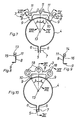
- FIGS. 1 to 6 first show burner tubes 1 with brackets 3 used for the storage of cooling rods 2, which form at least one cooling rod 2, at least in regions, comprising loops and are formed from a strip or wire.
- the band structure embodying the holder 3 according to FIG. 1 comprises the cooling rods 2 in its entirety, that is to say in a closed manner, and forms double-walled supporting webs below the cooling rods.
- such a holder 3 forms spread legs below the cooling rods 2 and in the embodiment according to FIG. 5 the band structure embodying the holder 3 only rests on the flanks of the cooling rods 2 and forms open, above these flank regions with divergent wings Insert the cooling rods 2 suitable recordings.
- All of these band structures have angle legs, the curvature of which corresponds to that of the wall of the burner tube 1 and are attached to this wall so as to lie flat against this wall.
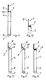
- Figures 7 to 18 show embodiments of brackets 3, which are attached to pipe clamps 4, with which they enclose the wall of the cylindrical burner tube 1.
- Such an annular pipe clamp 4 rests directly on the outside of the burner tube 1 and ends on its underside in two legs 6, parallel to each other while leaving a distance 5, the bores 7 of which are aligned and which can be pressed against one another by means of a bolt (not shown) around the pipe clamp 4 on the burner tube wall.
- the actual holder 3 is welded onto the top of this pipe clamp 4; it consists of a disc 8 with two support arms, which in turn bear flat, folded legs 9 on the burner tube wall. These two support arms delimit a recess 10 through which the flames of the burner can propagate from one side to the other of the holder 3 as soon as the burner is ignited.
- the radii defined by the center points of the grooves 11 include central angles ⁇ of a size of approximately 27 °.
- Figures 8 and 9 show sections VIII and IX, which are guided along the radii of the two outer grooves 11 and show that the holder 3 has fastening members in the form of bends 13 and 14 on its two lateral edges; one bend 13 has a hole 15, the other 14 has an undercut 16.
- the end of a bracket 17 can be passed through the hole 15, the other end of which can be anchored in the undercut 16 and which holds the cooling rods 2 in the grooves 11 and presses them against the bottom of these tapering grooves 11, so that they are also held axially in it.
- the associated second bracket 3 is shown in Figures 10 and 17; in terms of the organs used to attach it to the burner tube 1, it is the same as that shown in FIGS. 9 and 16.
- the holder 3 of this pipe clamp 4 has three round holes 18 for mounting the cooling rods 2, in which they slide and are only held radially .
- FIGS. 11 and 12 show cross sections of the holder 3 according to FIG. 10 in the planes XI-XI and XII-XII.
- FIGS. 13 to 15 represent design variants, according to which the retaining rods 3 are formed with an oblique stiffening and can be manufactured in one piece with the pipe clamp 4.
- FIG. 18 shows a single burner tube 1 in plan view.
- This burner tube 1 is closed on its end face 20 and a mixing tube 22 is provided at the opposite end 21, which opens into the burner tube 1 and into which a gas supply line 23 blows gas mixed with air via a gas nozzle 24.
- Groups of holes and groups of slots are arranged alternately as mixture outlet openings 25.
- the cooling rods 2 run such that they only cover areas of holes, but never areas of the slot groups. If larger and smaller recesses of another figuration are provided as mixture outlet openings 25, then the cooling rods 2 are to be dimensioned and arranged such that they cover or overflow each of the round openings.
- brackets 3 are provided, one of which is closer to the end face 20 according to FIG. 17, whereas the other according to FIG. 10 slides the cooling rods 2 by length changes due to different expansion coefficients of the material of the cooling rods 2 or the burner tube 1 to be able to compensate.
Landscapes
- Engineering & Computer Science (AREA)
- Chemical & Material Sciences (AREA)
- Combustion & Propulsion (AREA)
- Mechanical Engineering (AREA)
- General Engineering & Computer Science (AREA)
- Physics & Mathematics (AREA)
- Thermal Sciences (AREA)
- Gas Burners (AREA)
- Pre-Mixing And Non-Premixing Gas Burner (AREA)
Abstract
Description
- Die Erfindung bezieht sich auf einen atmosphärischen Gasbrenner mit wenigstens einem langgestreckten, innerhalb einer Brennkammer angeordneten Brennerrohr, dessen Wandung an ihrer Oberseite Gemischaustrittsöffnungen für ein dem Brennerrohr zugeführtes Gas-Luft-Gemisch aufweist, wobei diesem, vorzugsweise metallenen, Brennerrohr zumindest eine Halterung für zumindest einen, vorzugsweise aus keramischem Material bestehenden, im wesentlichen zur Achse des Brennerrohres parallelen, in einem Abstand von der Rohrwandung verlaufenden Kühlstab zugeordnet ist.
- Ein solcher Gasbrenner ist aus US-A- 4 525 141 und aus der DE-U- 8 507 804 bekannt. Bei dem aus der USA-A vorbekannten Gasbrenner dienen als Halterungen massive Ringe, die auf das Brennerrohr aufgeschoben und daran derart befestigt werden müssen, daß sie das Brennerrohr satt umschließen. Solche Ringe müssen naturgemäß für den jeweiligen Rohrdurchmesser des Brennerrohres mit einem einen Paßsitz ergebenden Innendurchmesser gefertigt bzw. auf Lager gehalten werden. Bedarf das Brennerrohr einer Wartung oder eines Austausches, müssen diese Ringe entweder mitausgetauscht oder zeitaufwendig abgenommen werden. Durch den Paßsitz dieser massiven Ringe ergibt sich auch eine unerwünscht gute Wärmeleitung zwischen dem zu kühlenden Brennerrohr und den zu seiner Kühlung bestimmten Kühlstäben, so daß ein Teil der von letzteren im Flammenbereich zweckdienlich aufgenommenen Hitze nicht abgeleitet, sondern in das Brennerrohr eingeleitet wird.
- Bei den aus der DE-U vorbekannten Gasbrennern dienen als Halterung von Kühlstäben U-förmig abgekantete Bleche, die sich mit einem Steg quer über das Brennerrohr erstrecken und mit zwei senkrechten Schenkeln an den Brennerrohrflanken tangierend befestigt sind. Durch diese Art der Befestigung wird aber die Wandung des Brennerrohres örtlich erheblich geschwächt und diese Befestigung, die außerdem höhenverstellbar sein soll, kann allzuleicht örtliche Schäden in dieser thermisch hochbeanspruchten Wandung verursachen und bildet diesbezüglich eine ständige Gefahrenquelle, zumal sich durch die Brennertemperaturen verursachte unterschiedlich thermisch bedingte Formänderungen zwangsläufig speziell in diesem Wandungsbereich ungünstig auswirken müssen.
- Erfindungsgemäß werden die oben geschilderten Nachteile der vorbekannten Halterungen bei einem Gasbrenner der eingangs bezeichneten Gattung dadurch vermieden, daß der Kühlstab, vorzugsweise eine Gruppe solcher Kühlstäbe gemeinsam, von zumindest einer an der Außenseite der Wandung des Brennerrohres bereichsweise aufliegend befestigten, als Halterung ausgebildeten Blechlamelle gehalten ist.
- Eine solche geeignet gestaltete Blechlamelle beansprucht wenig Raum, kann in Bereichen des Brennerrohres befestigt werden, die frei von Gemischaustrittsöffnungen sind und ist aus vergleichsweise dünnem Blech herstellbar, das dementsprechend eine geringe Wärmeleitfähigkeit besitzt. Dadurch, daß ein solches Blechgebilde bereichsweise satt auf der Brennerrohrwandung aufliegt, bildet es eine solide Halterung gleichwohl es mit geringem Arbeits- und Kostenaufwand aus einfach verarbeitbaren Material herstellbar ist.
- Für eine zweckdienliche Gestaltung der Halterung stehen im Rahmen der Erfindung vorteilhafterweise mannigfaltige Möglichkeiten offen.
- So kann eine solche Halterung erfindungsgemäß aus einem zumindest einen Kühlstab zumindest bereichsweise umfassenden, vorzugsweise aus einem Band geformten Gebilde bestehen. Ein solches Gebilde kann den Kühlstab umfanggeschlossen umfassen und unterhalb des Kühlstabes einen doppelwandigen Tragsteg oder divergierend gespreizte Tragbeine bilden. Man kann aber auch solche Gebilde in paarweiser Anordnung jeweils nur an Flankenbereichen von Kühlstäben anliegen und oberhalb dieser Flankenbereiche divergierend offene Halterungen bilden lassen.
- Ferner ist es im Rahmen der Erfindung auch möglich, die Halterungen an Rohrschellen zu befestigen, deren lichter Durchmesser dem Außendurchmesser des Brennerrohres entspricht und die an diesem konformen Brennerrohr anklemmbar sind.
- Weitere Erfindungsmerkmale solcher Rohrschellen sind nachstehend erläutert und bilden die Gegenstände von Unteransprüchen.
- Die Zeichnungen stellen Ausführungsbeispiele des Erfindungsgegenstandes dar, und zwar zeigt
- Figur 1 die Stirnansicht einer Halterung im Querschnitt durch das Brennerrohr und
- Figur 2 einen Teil-Längsschnitt durch den Bereich dieser Halterung.
- Figur 3 zeigt in gleicher Weise wie Fig.1 eine Variante und
- Figur 4 ist der zugehörige Längsschnitt nach IV-IV der Fig.3.
- Figur 5 stellt wiederum so wie Figur 1 eine weitere Ausführungsvariante dar und
- Figur 6 ist wieder der zugehörige Längsschnitt nach VI-VI der Figur 5.
- Figur 7 ist die Stirnansicht einer als Rohrschelle ausgebildeten Halterung,
- Figur 8 ist ein Schnitt nach VIII-VIII und
- Figur 9 ein Schnitt nach IX-IX der Figur 7.
- Figur 10 stellt eine abgewandelte Ausführungsform wieder in einer Stirnansicht dar und
- Figur 11 ist ein Vertikalschnitt nach XI-XI der Figur 10.
- Figur 12 bis 15 zeigen Ausführungsvarianten des oberen mit den Kühlstäben zusammenwirkenden Bereiches in Vertikalschnitten. Die
- Figuren 16 und 17 betreffen weitere Ausführungsvarianten solcher Rohrschellen in Querschnitten durch das Brennerrohr und
- Figur 18 ist eine Draufsicht auf ein mit solchen Halterungen ausgestattetes Brennerrohr.
- Die Figuren 1 bis 6 zeigen zunächst Brennerrohre 1 mit zur Lagerung von Kühlstäben 2 dienenden Halterungen 3, die zumindest einen Kühlstab 2 zumindest bereichsweise umfassende Schlaufen bilden und aus einem Band oder Draht geformt sind.
- Das die Halterung 3 verkörpernde Bandgebilde nach Figur 1 umfaßt die Kühlstäbe 2 zur Gänze, also umfanggeschlossen und bildet unterhalb der Kühlstäbe doppelwandige Tragstege.
- Gemäß der Ausführungsform nach Figur 3 bildet eine solche Halterung 3 unterhalb der Kühlstäbe 2 gespreizte Standbeine und bei der Ausführungsform nach Figur 5 liegt das die Halterung 3 verkörpernde Bandgebilde nur an den Flanken der Kühlstäbe 2 an und bildet oberhalb dieser Flankenbereiche mit divergierenden Flügeln offene, zum Einfügen der Kühlstäbe 2 geeignete Aufnahmen.
- Alle diese Bandgebilde besitzen Winkelschenkel, deren Krümmung jener der Wandung des Brennerrohres 1 entspricht und sind mittels dieser Winkelschenkel an dieser Wandung flächig anliegend befestigt.
- Die Figuren 7 bis 18 zeigen Ausführungsformen von Halterungen 3, die an Rohrschellen 4 befestigt sind, mit denen sie die Wandung des zylindrischen Brennerrohres 1 umschließen. Eine solche ringförmige Rohrschelle 4 liegt unmittelbar an der Außenseite des Brennerrohres 1 an und endet an ihrer Unterseite in zwei unter Belassung eines Abstandes 5 einander parallel gegenüberliegenden Schenkeln 6, deren Bohrungen 7 fluchten und die mittels eines nicht dargestellten Bolzens gegeneinander preßbar sind, um die Rohrschelle 4 an der Brennerrohrwandung auzuklemmen.
- Auf der Oberseite dieser Rohrschelle 4 ist die eigentliche Halterung 3 aufgeschweißt; sie besteht aus einer Scheibe 8 mit zwei Tragarmen, die ihrerseits an der Brennerrohrwandung flächig anliegende, abgekantete Schenkel 9 tragen. Diese beiden Tragarme begrenzen eine Ausnehmung 10, durch die sich die Flammen des Brenners von einer zur anderen Seite der Halterung 3 fortpflanzen können, sobald der Brenner gezündet wird.
- Gemäß Figur 7 und 10 sind im oberen Rand der Scheibe 8 der Halterung 3 drei sich abwärts verjüngende Nuten 11 angeordnet, deren Mittelpunkte auf einem Teilkreis 12 liegen, der zur Achse 13 des Brennerrohres 1 konzentrisch ist. Dadurch sind die Kühlstäbe 2 durchwegs gleich weit von der Brennerrohrwandung entfernt.
- Die von den Mittelpunkten der Nuten 11 definierten Radien schließen Zentriwinkel α einer Größe von etwa 27° ein.
- Die Figuren 8 und 9 zeigen Schnitte VIII und IX, die entlang der Radien der beiden äußeren Nuten 11 geführt sind und zeigen, daß die Halterung 3 an ihren beiden seitlichen Rändern Befestigungsorgane in Form von Abwinkelungen 13 bzw. 14 aufweist; die eine Abwinkelung 13 besitzt ein Loch 15, die andere 14 eine Hinterschneidung 16.
- Gemäß Figur 16 kann durch das Loch 15 das Ende eines Bügels 17 geführt werden, dessen anderes Ende sich in der Hinterschneidung 16 verankern läßt und der die Kühlstäbe 2 in den Nuten 11 festhält und sie gegen den Boden dieser sich verjüngenden Nuten 11 preßt, so daß sie darin auch axial festgehalten werden.
- Die zugehörige zweite Halterung 3 ist in den Figuren 10 und 17 dargestellt; sie ist hinsichtlich der zu ihrer Befestigung am Brennerrohr 1 dienenden Organe gleich jener nach den Figuren 9 und 16. Die Halterung 3 dieser Rohrschelle 4 weist jedoch drei runde Löcher 18 zur Lagerung der Kühlstäbe 2 auf, in denen diese gleitend lagern und nur radial gehalten sind.
- Die Figuren 11 und 12 zeigen Querschnitte der Halterung 3 gemäß Figur 10 in den Ebenen XI-XI und XII-XII. Die Figuren 13 bis 15 stellen Ausführungsvarianten dar, denenzufolge die Halterunen 3 mit einer Schrägversteifung ausge= bildet und mit der Rohrschelle 4 einstückig gefertigt sein können.
- Die Anordnung der Rohrschellen 4 am Brennerrohr 1 ist in der Figur 18 dargestellt, die ein einzelnes Brennerrohr 1 in Draufsicht zeigt. Dieses Brennerrohr 1 ist an seiner Stirnseite 20 geschlossen und am gegenüberliegenden Ende 21 ist ein Mischrohr 22 vorgesehen, das in das Brennerrohr 1 mündet und in das eine Gaszufuhrleitung 23 über eine Gasdüse 24 mit Luft vermischtes Gas einbläst.
- Als Gemischaustrittsöffnungen 25 sind Gruppen von Löchern und Gruppen von Schlitzen alternierend angeordnet. Die Kühlstäbe 2 verlaufen derart, daß sie nur Bereiche von Löchern abdecken, aber nie Bereiche der Schlitzgruppen. Sind als Gemischaustrittsöfnungen25 größere und kleinere Ausnehmungen anderer Figuration vorgesehen, dann sind die Kühlstäbe 2 so zu bemessen und anzuordnen, daß sie jeweils die runden Öffnungen abdecken bzw. überlaufen.
- Aus der Figur 18 ist auch ersichtlich, daß jeweils zweierlei Halterungen 3 vorgesehen sind, von denen die der Stirnseite 20 nähere nach Figur 17 ausgebildet ist, wogegen die andere nach Figur 10 die Kühlstäbe 2 gleitend lagert, um Längenänderungen infolge unterschiedlicher Ausdehnungskoeffizienten des Materiales der Kühlstäbe 2 bzw. des Brennerrohres 1 ausgleichen zu können.
Claims (10)
Applications Claiming Priority (14)
| Application Number | Priority Date | Filing Date | Title |
|---|---|---|---|
| DE3535937 | 1985-10-05 | ||
| DE3535937 | 1985-10-05 | ||
| AT371985A AT388794B (de) | 1985-12-23 | 1985-12-23 | Halterung |
| AT3719/85 | 1985-12-23 | ||
| DE8605042U | 1986-02-25 | ||
| DE19868605042 DE8605042U1 (de) | 1986-02-25 | 1986-02-25 | Gasbrenner |
| AT175286A AT389374B (de) | 1986-06-27 | 1986-06-27 | Atmosphaerischer gasbrenner |
| AT1752/86 | 1986-06-27 | ||
| DE19868622113 DE8622113U1 (de) | 1986-08-18 | 1986-08-18 | Gasbrenner |
| DE8622113U | 1986-08-18 | ||
| DE8622799U | 1986-08-26 | ||
| DE19868622799 DE8622799U1 (de) | 1986-08-26 | 1986-08-26 | Atmosphärischer Gasbrenner |
| DE19868623133 DE8623133U1 (de) | 1986-08-28 | 1986-08-28 | Brennerplatte |
| DE8623133U | 1986-08-28 |
Related Parent Applications (1)
| Application Number | Title | Priority Date | Filing Date |
|---|---|---|---|
| EP86905737.2 Division | 1986-10-06 |
Publications (2)
| Publication Number | Publication Date |
|---|---|
| EP0326185A1 true EP0326185A1 (de) | 1989-08-02 |
| EP0326185B1 EP0326185B1 (de) | 1992-04-29 |
Family
ID=27560412
Family Applications (5)
| Application Number | Title | Priority Date | Filing Date |
|---|---|---|---|
| EP89102124A Expired - Lifetime EP0323439B1 (de) | 1985-10-05 | 1986-10-06 | Atmosphärischer Gasbrenner |
| EP86905737A Expired - Lifetime EP0238572B1 (de) | 1985-10-05 | 1986-10-06 | Atmosphärischer gasbrenner |
| EP89102125A Expired - Lifetime EP0322399B2 (de) | 1985-10-05 | 1986-10-06 | Atmosphärischer Gasbrenner |
| EP89102126A Expired - Lifetime EP0326185B1 (de) | 1985-10-05 | 1986-10-06 | Atmosphärischer Gasbrenner |
| EP89102123A Expired - Lifetime EP0327135B1 (de) | 1985-10-05 | 1986-10-06 | Atmosphärischer Gasbrenner |
Family Applications Before (3)
| Application Number | Title | Priority Date | Filing Date |
|---|---|---|---|
| EP89102124A Expired - Lifetime EP0323439B1 (de) | 1985-10-05 | 1986-10-06 | Atmosphärischer Gasbrenner |
| EP86905737A Expired - Lifetime EP0238572B1 (de) | 1985-10-05 | 1986-10-06 | Atmosphärischer gasbrenner |
| EP89102125A Expired - Lifetime EP0322399B2 (de) | 1985-10-05 | 1986-10-06 | Atmosphärischer Gasbrenner |
Family Applications After (1)
| Application Number | Title | Priority Date | Filing Date |
|---|---|---|---|
| EP89102123A Expired - Lifetime EP0327135B1 (de) | 1985-10-05 | 1986-10-06 | Atmosphärischer Gasbrenner |
Country Status (5)
| Country | Link |
|---|---|
| US (1) | US4915620A (de) |
| EP (5) | EP0323439B1 (de) |
| AT (5) | ATE100556T1 (de) |
| DE (5) | DE3685119D1 (de) |
| WO (1) | WO1987002118A1 (de) |
Cited By (1)
| Publication number | Priority date | Publication date | Assignee | Title |
|---|---|---|---|---|
| EP0434977A1 (de) * | 1989-11-24 | 1991-07-03 | Joh. Vaillant GmbH u. Co. | Heizkessel |
Families Citing this family (7)
| Publication number | Priority date | Publication date | Assignee | Title |
|---|---|---|---|---|
| AT399031B (de) * | 1992-11-12 | 1995-03-27 | Vaillant Gmbh | Halter zur aufnahme von flammenkühlstäben |
| AT404178B (de) * | 1995-05-29 | 1998-09-25 | Vaillant Gmbh | Brenner |
| DE102008015915A1 (de) * | 2008-03-27 | 2009-10-15 | Giese, Michael, Dr.-Ing. | Motor |
| DE102013224629A1 (de) | 2013-11-29 | 2015-06-03 | Robert Bosch Gmbh | Brenner |
| EP3232133A1 (de) * | 2016-04-13 | 2017-10-18 | Liju Thermal Equipment Technology Co., Ltd | Brenner mit niedrigem nox-gehalt |
| WO2018070009A1 (ja) * | 2016-10-13 | 2018-04-19 | 三菱電機株式会社 | ヒートポンプ装置 |
| DE102021103841A1 (de) | 2021-02-18 | 2022-08-18 | Vaillant Gmbh | Brenner für ein Heizgerät und seine Anordnung im Heizgerät |
Citations (4)
| Publication number | Priority date | Publication date | Assignee | Title |
|---|---|---|---|---|
| DE8507804U1 (de) * | 1985-03-16 | 1985-05-15 | Viessmann Werke Kg, 3559 Allendorf | Atmosphärischer Gasbrenner |
| US4525141A (en) * | 1983-07-11 | 1985-06-25 | Gas Research Institute | Regulation of blue flame combustion emissions |
| DE8526207U1 (de) * | 1985-09-13 | 1985-10-31 | Viessmann Werke Kg, 3559 Allendorf | Gasheizkessel |
| DE8603672U1 (de) * | 1986-02-12 | 1986-04-10 | Viessmann Werke Kg, 3559 Allendorf | Atmosphärischer Gasbrenner |
Family Cites Families (8)
| Publication number | Priority date | Publication date | Assignee | Title |
|---|---|---|---|---|
| US2379524A (en) * | 1940-11-22 | 1945-07-03 | Roper Corp Geo D | Gas burner |
| US2808047A (en) * | 1956-05-09 | 1957-10-01 | Syncromatic Corp | Gas fired hot air furnace |
| GB1232596A (de) * | 1967-09-29 | 1971-05-19 | ||
| US4285666A (en) * | 1977-11-10 | 1981-08-25 | Burton Chester G | Apparatus and method for increasing fuel efficiency |
| US4629415A (en) * | 1983-07-11 | 1986-12-16 | Gas Research Institute | Flame insert |
| US4616994A (en) * | 1984-10-05 | 1986-10-14 | Heil-Quaker Corporation | Gas burner with means for reducing NOx emissions |
| DE8528666U1 (de) * | 1985-10-05 | 1986-01-23 | Joh. Vaillant Gmbh U. Co, 5630 Remscheid | Brenner, insbesondere Gasbrenner |
| DE8604052U1 (de) * | 1986-02-13 | 1986-04-03 | Joh. Vaillant Gmbh U. Co, 5630 Remscheid | Brenner für ein gasbeheiztes Gerät |
-
1986
- 1986-10-06 EP EP89102124A patent/EP0323439B1/de not_active Expired - Lifetime
- 1986-10-06 WO PCT/DE1986/000406 patent/WO1987002118A1/de not_active Ceased
- 1986-10-06 DE DE8989102126T patent/DE3685119D1/de not_active Expired - Lifetime
- 1986-10-06 EP EP86905737A patent/EP0238572B1/de not_active Expired - Lifetime
- 1986-10-06 AT AT86905737T patent/ATE100556T1/de not_active IP Right Cessation
- 1986-10-06 DE DE8989102123T patent/DE3679831D1/de not_active Expired - Lifetime
- 1986-10-06 EP EP89102125A patent/EP0322399B2/de not_active Expired - Lifetime
- 1986-10-06 AT AT89102126T patent/ATE75533T1/de not_active IP Right Cessation
- 1986-10-06 DE DE86905737T patent/DE3689565D1/de not_active Expired - Fee Related
- 1986-10-06 DE DE8989102124T patent/DE3683506D1/de not_active Expired - Lifetime
- 1986-10-06 AT AT89102123T patent/ATE64449T1/de not_active IP Right Cessation
- 1986-10-06 AT AT89102124T patent/ATE71706T1/de not_active IP Right Cessation
- 1986-10-06 EP EP89102126A patent/EP0326185B1/de not_active Expired - Lifetime
- 1986-10-06 AT AT89102125T patent/ATE69870T1/de not_active IP Right Cessation
- 1986-10-06 EP EP89102123A patent/EP0327135B1/de not_active Expired - Lifetime
- 1986-10-06 DE DE8989102125T patent/DE3682685D1/de not_active Expired - Lifetime
-
1987
- 1987-08-20 US US07/138,491 patent/US4915620A/en not_active Expired - Fee Related
Patent Citations (4)
| Publication number | Priority date | Publication date | Assignee | Title |
|---|---|---|---|---|
| US4525141A (en) * | 1983-07-11 | 1985-06-25 | Gas Research Institute | Regulation of blue flame combustion emissions |
| DE8507804U1 (de) * | 1985-03-16 | 1985-05-15 | Viessmann Werke Kg, 3559 Allendorf | Atmosphärischer Gasbrenner |
| DE8526207U1 (de) * | 1985-09-13 | 1985-10-31 | Viessmann Werke Kg, 3559 Allendorf | Gasheizkessel |
| DE8603672U1 (de) * | 1986-02-12 | 1986-04-10 | Viessmann Werke Kg, 3559 Allendorf | Atmosphärischer Gasbrenner |
Cited By (1)
| Publication number | Priority date | Publication date | Assignee | Title |
|---|---|---|---|---|
| EP0434977A1 (de) * | 1989-11-24 | 1991-07-03 | Joh. Vaillant GmbH u. Co. | Heizkessel |
Also Published As
| Publication number | Publication date |
|---|---|
| EP0238572B1 (de) | 1994-01-19 |
| EP0322399A1 (de) | 1989-06-28 |
| DE3683506D1 (de) | 1992-02-27 |
| ATE71706T1 (de) | 1992-02-15 |
| EP0238572A1 (de) | 1987-09-30 |
| ATE75533T1 (de) | 1992-05-15 |
| EP0327135B1 (de) | 1991-06-12 |
| DE3682685D1 (de) | 1992-01-09 |
| EP0322399B1 (de) | 1991-11-27 |
| DE3685119D1 (de) | 1992-06-04 |
| ATE100556T1 (de) | 1994-02-15 |
| EP0323439B1 (de) | 1992-01-15 |
| EP0322399B2 (de) | 1994-09-28 |
| US4915620A (en) | 1990-04-10 |
| ATE69870T1 (de) | 1991-12-15 |
| EP0323439A1 (de) | 1989-07-05 |
| WO1987002118A1 (fr) | 1987-04-09 |
| ATE64449T1 (de) | 1991-06-15 |
| DE3689565D1 (de) | 1994-03-03 |
| EP0326185B1 (de) | 1992-04-29 |
| DE3679831D1 (de) | 1991-07-18 |
| EP0327135A1 (de) | 1989-08-09 |
Similar Documents
| Publication | Publication Date | Title |
|---|---|---|
| DE69810610T2 (de) | Expandierbarer bohrlochfilter | |
| DE2653905C3 (de) | Wärmeübertrager mit einem Bündel schraubenlinienförmig gewundener Rohre | |
| EP0331690A1 (de) | Deckenverkleidung | |
| EP0326185B1 (de) | Atmosphärischer Gasbrenner | |
| DE2513622C3 (de) | Trägergestellanordnung zur Aufnahme von Töpferwaren o.dgl | |
| EP0594939B1 (de) | Fussgestell für Tische und dergleichen | |
| DE3907421C2 (de) | ||
| EP0396908A2 (de) | Roststab und Rostwalze | |
| EP1164230B1 (de) | Anordnung zur Befestigung von Plattenmaterial, insbesondere von Glasscheiben, an Standsäulen oder dergleichen | |
| DE2646085C2 (de) | In seiner Länge verstellbares Spiegelisolierelement | |
| DE3826508A1 (de) | Auflagerung einer axial fixierten dampfturbine | |
| DE9110246U1 (de) | Flächenbrenner | |
| EP0309950B1 (de) | Atmosphärischer Gasbrenner | |
| DE3232794C2 (de) | Brennkammerboden zu einer Wirbelschichtfeuerung | |
| DE69108361T2 (de) | Wärmetauschanordnung. | |
| DE2251866A1 (de) | Vorrichtung zur halterung und distanzierung von rohren in einem waermetauscher | |
| DE2840401C2 (de) | Wabendecke | |
| DE2945087C2 (de) | Tragrost für eine Füllkörper-Kolonne | |
| DE9102991U1 (de) | Gas-Flächenbrenner | |
| EP0209703B1 (de) | Glüheinsatz für Öfen, insbesondere Heizungskessel, sowie Ofen mit einem derartigen Glüheinsatz | |
| DE3314827A1 (de) | Boden fuer eine stoffaustauschkolonne | |
| DE4030135C2 (de) | Düsenkranz für einen Flüssigpropangasbrenner für Heißluftballons sowie ein Verfahren zur Herstellung | |
| DE3128601A1 (de) | Roehrenofen | |
| AT407433B (de) | Brenner | |
| AT389374B (de) | Atmosphaerischer gasbrenner |
Legal Events
| Date | Code | Title | Description |
|---|---|---|---|
| PUAI | Public reference made under article 153(3) epc to a published international application that has entered the european phase |
Free format text: ORIGINAL CODE: 0009012 |
|
| AC | Divisional application: reference to earlier application |
Ref document number: 238572 Country of ref document: EP |
|
| AK | Designated contracting states |
Kind code of ref document: A1 Designated state(s): AT BE CH DE FR GB IT LI LU NL SE |
|
| 17P | Request for examination filed |
Effective date: 19891214 |
|
| 17Q | First examination report despatched |
Effective date: 19910129 |
|
| RAP1 | Party data changed (applicant data changed or rights of an application transferred) |
Owner name: VAILLANT GMBH Owner name: VAILLANT-SCHONEWELLE B.V. Owner name: VAILLANT LTD. Owner name: VAILLANT GES.M.B.H Owner name: VAILLANT S.A.R.L Owner name: N.V. VAILLANT S.A. Owner name: JOH. VAILLANT GMBH U. CO. |
|
| GRAA | (expected) grant |
Free format text: ORIGINAL CODE: 0009210 |
|
| AC | Divisional application: reference to earlier application |
Ref document number: 238572 Country of ref document: EP |
|
| AK | Designated contracting states |
Kind code of ref document: B1 Designated state(s): AT BE CH DE FR GB IT LI LU NL SE |
|
| REF | Corresponds to: |
Ref document number: 75533 Country of ref document: AT Date of ref document: 19920515 Kind code of ref document: T |
|
| REF | Corresponds to: |
Ref document number: 3685119 Country of ref document: DE Date of ref document: 19920604 |
|
| ITF | It: translation for a ep patent filed | ||
| GBT | Gb: translation of ep patent filed (gb section 77(6)(a)/1977) | ||
| ET | Fr: translation filed | ||
| PGFP | Annual fee paid to national office [announced via postgrant information from national office to epo] |
Ref country code: BE Payment date: 19920911 Year of fee payment: 7 |
|
| PGFP | Annual fee paid to national office [announced via postgrant information from national office to epo] |
Ref country code: GB Payment date: 19920921 Year of fee payment: 7 |
|
| PGFP | Annual fee paid to national office [announced via postgrant information from national office to epo] |
Ref country code: SE Payment date: 19920929 Year of fee payment: 7 Ref country code: FR Payment date: 19920929 Year of fee payment: 7 |
|
| PGFP | Annual fee paid to national office [announced via postgrant information from national office to epo] |
Ref country code: LU Payment date: 19920930 Year of fee payment: 7 |
|
| PGFP | Annual fee paid to national office [announced via postgrant information from national office to epo] |
Ref country code: NL Payment date: 19921031 Year of fee payment: 7 |
|
| PLBE | No opposition filed within time limit |
Free format text: ORIGINAL CODE: 0009261 |
|
| STAA | Information on the status of an ep patent application or granted ep patent |
Free format text: STATUS: NO OPPOSITION FILED WITHIN TIME LIMIT |
|
| EPTA | Lu: last paid annual fee | ||
| 26N | No opposition filed | ||
| PG25 | Lapsed in a contracting state [announced via postgrant information from national office to epo] |
Ref country code: LU Free format text: LAPSE BECAUSE OF NON-PAYMENT OF DUE FEES Effective date: 19931006 Ref country code: GB Effective date: 19931006 |
|
| PG25 | Lapsed in a contracting state [announced via postgrant information from national office to epo] |
Ref country code: SE Effective date: 19931007 |
|
| NLT1 | Nl: modifications of names registered in virtue of documents presented to the patent office pursuant to art. 16 a, paragraph 1 |
Owner name: VAILLANT B.V. TE AMSTERDAM. |
|
| PG25 | Lapsed in a contracting state [announced via postgrant information from national office to epo] |
Ref country code: BE Effective date: 19931031 |
|
| BERE | Be: lapsed |
Owner name: S.A. VAILLANT N.V. Effective date: 19931031 |
|
| PG25 | Lapsed in a contracting state [announced via postgrant information from national office to epo] |
Ref country code: NL Effective date: 19940501 |
|
| GBPC | Gb: european patent ceased through non-payment of renewal fee |
Effective date: 19931006 |
|
| NLV4 | Nl: lapsed or anulled due to non-payment of the annual fee | ||
| PG25 | Lapsed in a contracting state [announced via postgrant information from national office to epo] |
Ref country code: FR Effective date: 19940630 |
|
| REG | Reference to a national code |
Ref country code: FR Ref legal event code: ST |
|
| EUG | Se: european patent has lapsed |
Ref document number: 89102126.3 Effective date: 19940510 |
|
| PGFP | Annual fee paid to national office [announced via postgrant information from national office to epo] |
Ref country code: AT Payment date: 19990908 Year of fee payment: 14 |
|
| PGFP | Annual fee paid to national office [announced via postgrant information from national office to epo] |
Ref country code: CH Payment date: 19991117 Year of fee payment: 14 |
|
| PG25 | Lapsed in a contracting state [announced via postgrant information from national office to epo] |
Ref country code: AT Free format text: LAPSE BECAUSE OF NON-PAYMENT OF DUE FEES Effective date: 20001006 |
|
| PG25 | Lapsed in a contracting state [announced via postgrant information from national office to epo] |
Ref country code: LI Free format text: LAPSE BECAUSE OF NON-PAYMENT OF DUE FEES Effective date: 20001031 Ref country code: CH Free format text: LAPSE BECAUSE OF NON-PAYMENT OF DUE FEES Effective date: 20001031 |
|
| REG | Reference to a national code |
Ref country code: CH Ref legal event code: PL |
|
| PGFP | Annual fee paid to national office [announced via postgrant information from national office to epo] |
Ref country code: DE Payment date: 20021112 Year of fee payment: 17 |
|
| PG25 | Lapsed in a contracting state [announced via postgrant information from national office to epo] |
Ref country code: DE Free format text: LAPSE BECAUSE OF NON-PAYMENT OF DUE FEES Effective date: 20040501 |
|
| PG25 | Lapsed in a contracting state [announced via postgrant information from national office to epo] |
Ref country code: IT Free format text: LAPSE BECAUSE OF NON-PAYMENT OF DUE FEES;WARNING: LAPSES OF ITALIAN PATENTS WITH EFFECTIVE DATE BEFORE 2007 MAY HAVE OCCURRED AT ANY TIME BEFORE 2007. THE CORRECT EFFECTIVE DATE MAY BE DIFFERENT FROM THE ONE RECORDED. Effective date: 20051006 |