EP0326295A1 - Méthode d'agrandissement des données sous forme d'une matrice de bits selon la direction horizontale - Google Patents
Méthode d'agrandissement des données sous forme d'une matrice de bits selon la direction horizontale Download PDFInfo
- Publication number
- EP0326295A1 EP0326295A1 EP89300559A EP89300559A EP0326295A1 EP 0326295 A1 EP0326295 A1 EP 0326295A1 EP 89300559 A EP89300559 A EP 89300559A EP 89300559 A EP89300559 A EP 89300559A EP 0326295 A1 EP0326295 A1 EP 0326295A1
- Authority
- EP
- European Patent Office
- Prior art keywords
- data
- bit map
- horizontal direction
- bit
- font data
- Prior art date
- Legal status (The legal status is an assumption and is not a legal conclusion. Google has not performed a legal analysis and makes no representation as to the accuracy of the status listed.)
- Granted
Links
Images






Classifications
-
- G—PHYSICS
- G06—COMPUTING OR CALCULATING; COUNTING
- G06V—IMAGE OR VIDEO RECOGNITION OR UNDERSTANDING
- G06V10/00—Arrangements for image or video recognition or understanding
- G06V10/20—Image preprocessing
- G06V10/32—Normalisation of the pattern dimensions
-
- G—PHYSICS
- G06—COMPUTING OR CALCULATING; COUNTING
- G06K—GRAPHICAL DATA READING; PRESENTATION OF DATA; RECORD CARRIERS; HANDLING RECORD CARRIERS
- G06K15/00—Arrangements for producing a permanent visual presentation of the output data, e.g. computer output printers
- G06K15/02—Arrangements for producing a permanent visual presentation of the output data, e.g. computer output printers using printers
-
- G—PHYSICS
- G06—COMPUTING OR CALCULATING; COUNTING
- G06K—GRAPHICAL DATA READING; PRESENTATION OF DATA; RECORD CARRIERS; HANDLING RECORD CARRIERS
- G06K2215/00—Arrangements for producing a permanent visual presentation of the output data
- G06K2215/0002—Handling the output data
- G06K2215/004—Generic data transformation
- G06K2215/0054—Geometric transformations, e.g. on rasterised data
- G06K2215/0057—Sizing and resolution changes
Definitions
- the present invention relates to a method of magnifying a bit map font data in a horizontal direction, more particularly, it relates to a method of magnifying a bit map font data suitable for half density print, in a horizontal direction and at a predetermined magnification rate, to obtain a magnified bit map font data still suitable for half density printing.
- Dot matrix printers for example, twenty-four pin dot matrix printers, have a characteristics such that the quality of a printed character is high, and that various modifications of a character style are possible. On such modification is a magnification of a character.
- the simplest algorithm used for magnifying a character made of a bit map data, in a horizontal/vertical direction is a method of multiplying each bit in each of the horizontal/vertical directions by each magnification rate, e.g., at a magnification rate of two, as shown in Figure 1.
- bit map data modified for the half density printing is shown in Figure 2. This is a bit map font data for a number "4".
- the half density printing method can produce various types of character style, for example, Gothic style, Italic style, or even a cursive script style, in detail, and smoothly, with a good aesthetic appearance.
- FIG. 2 shows a simulated printing result of the bit map data of Fig. 2, wherein each circle filled with oblique lines shows a printed dot mark corresponding to one dot indicated by a black mesh in Fig. 2.
- bit map data for the half density printing is that, as shown in Fig. 2, a "1" dot is not followed by a "1" dot in a series of bit data representing a solid line in the horizontal direction, and more than a predetermined number (for example, two in Fig. 2) of successive "0's" does not appear in the solid line, where "1" means print, and "0" means not print.
- Figures 4 and 5 show an outline of the construction of a dot matrix printer.
- reference numeral 11 denotes a platen
- 12 denotes a paper
- 22 denotes a printing head
- 21 denotes a carriage for the printing head
- 221-1, 221-2, ... 221-24 denote twenty-four head pins (dot wires).
- the twenty-four head pins (dot wires) 221-1, 221-2, ... 221-24 are mounted in a portion 221 which protrudes toward the platen 11, in the printing head 22, and each of the head pins (dot wires) 221-1, 221-2, ... 221-24 is moved toward the platen 11 by driving an exciting coil (not shown) provided to move each of the head pins 221-1, 221-2, ... 221-24.
- a paper 12 and an ink ribbon (not shown) are set to intervene between the tops of the head pins 221-1,221-2, ...221-24 and the surface of the platen 11.
- the head pins 221-1,221-2, ...221-24 are arranged in a row in the direction vertical to the axis of the platen 11, and parallel to a tangent line of a circumference of the platen 11, and thus, for example, a series of data in each column (each series of data in the vertical direction) of the bit map data of Fig. 2, can be printed on the paper 12 at one time.
- each series of data in each column in a bit map font data (for example, each series of data in each column in the bit map font data as shown in Fig. 2) is printed on a paper 12, one column by one column.
- the speed of printing greatly depends on the speed at which the carriage 21 is moved, but this speed is limited by the time needed for each head pin 221-i to press a succeeding dot after pressing a preceding dot, i.e., a recovery time or cycle time of a piston motion of a head pin 221-i, when printing two dots in succession, driven by an exciting coil.
- a series of bit data representing a solid line in the horizontal direction includes successive "1's", where "1" means print
- the carriage 21 moves in the horizontal direction at a speed of less than one dot per T (sec), where T (sec) is the abovementioned cycle time of the piston motion of each head pin 221-i, but, if the above mentioned series of bit data, representing a solid line in the horizontal direction and including successive "1's", is modified so that no successive "1's" are included in the series of bit data, the speed at which the carriage 21 is moved can be made faster than the speed of the carriage in the abovementioned case when including successive "1's".
- a series of bit data representing a solid line in the horizontal direction are made to have a "1" on alternate dots, the moving speed of the carriage 21 can be made doubled compared with the abovementiond case including successive "1's".
- the series of bit data representing a solid line in the horizontal direction in the bit map data shown in Fig. 2 includes two successive "0's". These successive "0's" are provided for maintaining a length of the solid line represented mainly by the alternate dots, i.e., for making each end dot of the solid line "1".
- the lengths of solid lines which are a part of a character must be maintained even after magnification, to maintain the character style.
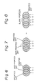
- Figures 5, 6, and 7 show a sampled portion consisting of marks made by printed dots and not-printed dots corresponding to a series of bit data, respectively, under a predetermined dimensional condition of a pitch of the dots in the horizontal direction and a diameter of a mark printed by a dot data "1", for example, a pitch of the dots is 1/360"(0.07 mm) and a diameter of a mark is 1/120" (about 0.2mm) ⁇ .
- a printed dot is shown by a circle filled with oblique lines, and a not-printed dot is shown by a blank circle. The very large overlap of the circles indicating dots adjacent to each other, creates the smoothness of outlines of the printed character made by a series of dot marks.
- the marks made by printed dots and a not-printed dot shown in Fig. 6, corresponds to a series of bit data "101"
- the marks made by printed dots and not-printed dots shown in Fig. 7 corresponds to a series of bit data "1001”
- the marks made by printed dots and not-printed dots shown in Fig. 8 corresponds to a series of bit data "10001”.
- a maximum allowable number of successive "0's" in a series of bit data to represent a solid line in the horizontal direction in a bit map font data for half density printing will change.
- a general requirement for a series of bit data to represent a solid line in the horizontal direction in a bit map font data for half density printing is that a "1" dot is not followd by a "1”, and that more than a predetermined number of successive "0's" do not appear in the series of bit data, and a series of bit data representing a solid line in the horizontal direction must still satisfy the above requirement even after magnification in the horizontal direction.
- Figure 9 shows an example of a detailed process of carrying out a conventional method of magnifying a bit map font data for half density printing in the horizontal direction at a magnification rate of three.
- a series of bit data in the horizontal direction which is sampled from the portion shown by (A) in the bit map font data of Fig. 2, which is shown in Figure 10, is used as an original series of bit data to be magnified in the horizontal direction.
- an intermediate magnification-stage magnified element is generated from each bit of the original series of bit data as follows: an original bit “1” generates h "10's” where h is a magnification rate; and an original bit “0” generates h "00's", e.g., when the magnification rate is three, an original bit "1” generates "101010”; and an original bit “0” generates "000000".
- the positions of columns for the intermediate-stage magnified element for each of the original "1's” and “0's” are arranged in the order in which the "1's” and “0's” are arranged in the original font data, and the positions of the two intermediate-stage magnified elements adjacent to each other are arranged with a difference of h columns.
- FIG. 11 A general algorithm to obtain the value of each bit in the magnified series of bit data by the conventional method of magnifying a bit map font data for half density printing in the horizontal direction, which covers the abovementioned process of the magnification shown in Fig. 9, is shown in Figure 11, using a flow chart.
- a column number of an original data is shown by "a”
- a column number of a magnified data is shown by "b”
- a total number of columns constituting the original bit map data is shown by "W”.
- step 103 corresponding to, for example, the operation at the third step in the aforementioned process of Fig. 9, means that the magnified bit map data obtained in all cycles in the process of Fig. 12 must be superposed, and the above AND logic calculation in the step 103 means that a "1" dot must not be followed by a "1" dot (hereinafter called a successive "1's" inhibition rule).
- the values in the columns corresponding to the even-numbered columns in the aforementioned intermediate magnification-stage magnified element for example, "0's" in the aforementioned h "10's” in Fig. 9, are not calculated, because these are always zero, and do not affect the result of the OR calculation.
- the result of the magnified bit map data of Fig. 9, includes more than two successive "0's”, i.e., "0000". Under the aforementioned dimensional condition of the pitch of dots and the diameter of the printed dots, as understood by referring to Fig. 8, these successive "0's”, i.e., "0000", generate a blank portion in a solid line when printed.
- a method of magnifying bit map font data for half density printing comprising a step of magnifying the bit map font data in the horizontal direction at a predetermined magnification rate, is characterised in that the method includes a first step, before the magnifying step, of reducing a number of successive "0's" in a portion of the bit map font data which represents a solid line in the horizontal direction, to not more than a predetermined number, by replacing one "0" of more than the predetermined number of successive "0's” with a "1".
- the advantage of the present invention is the provision of a method of magnifying bit map font data for half density printing in the horizontal direction at a predetermined magnification rate, without generating a blank portion in a solid line in the horizontal direction when printed after magnification.
- the first aspect of the present invention is a method of magnifying a bit map font data in a horizontal direction, which comprises: a first step of reducing the number of successive "0's" in a portion which represents a solid line in the horizontal direction in the bit map font data, to not more than a first predetermined number, by replacing one or some "0's" among the more than first predetermined number of successive "0's” with a "1"; and a second step of magnifying the bit map font data for half density printing after the above replacement, in the horizontal direction at a predetermined magnification rate.
- the above first predetermined number determined as a number such that, when more than the first predetermined number of successive "0's" appear in a series of the original bit data; which series of the original bit data should represent a solid line when printed, more than a second predetermined number of successive "0's” appear in a series of bit data which are generated by magnifying the above series of the original bit data in the horizontal direction, where the appearance of more than the second predetermined number of successive "0's" in a series of bit data, which should represent a solid line when printed, generates a blank portion in the portion which should represent a solid line when printed.
- the method of magnifying a bit map font data for half density printing in the horizontal direction enables the prevention of an appearance of a blank (a not-printed portion) in a portion which should represent a solid line when printed, after magnification in the horizontal direction.
- an additional step is added after the above second step in the first aspect of the present invention.
- a correction of a magnified bit map font data obtained by the second step so that a "1" is not followed by a “1” in the horizontal direction in a resultant bit map font data is carried out, when a "1" is followed by another "1” in the above magnified bit map font data obtained by the above second step.
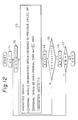
- Figure 12 shows a general algorithm used to obtain the value of each bit in the magnified series of bit data by a method of magnifying a bit map font data for half density printing in the horizontal direction according to the present invention, which algorithm covers a detailed process of the magnification shown in Fig. 13 which is explained later.
- Figure 12 corresponds to Fig. 11 which shows a general algorithm used in the prior art. Note the denotations of the parameters "a", “b", and “W” in Fig. 12 are the same as in Fig. 11.
- the algorithm according to the present invention is different from the conventional algorithm of Fig. 11, only in the basic equation for writing a magnified data for generating a magnified data at step 113, to obtain a value (b) of each column b in the magnified bit data.
- step 113 a calculation of an AND logic of the value (a-2) of two columns before the corresponding column a in the original series of bit data, and the value (a+1) of the next column a+1 in the original series of bit data, is carried out; and then a calculation of an OR logic of the value (a) of the correponding column a in the original series of bit data, the value (b) of the same column b obtained in the previous cycles, and the result of the above AND logic calculation, is carried out; and finally, a calculation of an AND logic of the result of the above OR logic calculation of each column b and the inverted value (b-1) of the one column before in the magnified bit map data, is carried out.
- step 113 means that a "1" dot should not be followed by a "1" dot, and this is the aforementioned successive "0's" inhibition rule in a series of bit data as the final result of the magnification, as in the case at step 103 of Fig. 11.
- the above OR logic calculation at step 113 means that the magnified bit map data obtained in all cycles in the process of Fig. 12 must be superposed, as in the case at step 103 of Fig. 11. According to the present invention, however, at the step 113, the calculation result of the AND logic of the value (a-2) of two columns before the corresponding column a in the original series of bit data, and the value (a+1) of the next column a+1 in the original series of bit data is superposed in addition to the superposed data at the conventional step 103 in Fig. 11.
- the above AND logic means that, when both the value (a-2) of two columns before the corresponding column a in the original series of bit data, and the value (a+1) of the next column a+1 in the original series of bit data, are "1", the value (a) of the column a is deemed “1” regardless of the actual value (a) of the column a, e.g., when the values (a-2, a-1, a, a+1) of the columns "a-2, a-1, a, a+1” in the original series of bit data are "1001", these are deemed “1011” before an operation of magnification by step 113 of Fig. 12.
- this is an example of the realization of the aforementioned first step of the present invention for reducing the number of successive "0's" in the portion which represents a solid line in the horizontal direction in a bit map font data to not more than a first predetermined number, by replacing one or some "0's" among the more than the first predetermined number of successive "0's", with a "1".
- the combination of (a-2) and (a+1) can be replaced by a combination of (a-1) and (a+2).
- Figure 13 shows an example of a detailed process of carrying out a method of magnifying a bit map font data for half density printing in the horizontal direction, realizing the algorithm of Fig. 12.
- an intermediate-stage magnified element is generated from each bit of the series of the bit data obtained through the first step, as follows: a bit "1" in the series of data obtained through the first step generates h "10's” where h is a magnification rate; and a bit “0” generates h "00's", e.g., when the magnification rate is three, a bit "1” generates "101010”; and a bit "0” generates "000000".
- the positions of columns for the intermediate-stage magnified element for each of the above “1's” and “0's” are arranged in the order in which the "1's” and “0's” are arranged in the series of data obtained through the first step, and the positions of the two intermediate-stage magnified elements adjacent to each other are arranged with a difference of h columns.
- the aforementioned successive "1's” inhibition rule in the series of magnified bit data as a final result is applied to the resultant series of bit data obtained through the above fourth step.
- This step is necessary because successive "1's” might appear in the resultant series of bit data obtained through the above fourth step, e.g., "1111" shown in the example of Fig. 13.
- successive "1's" in the resultant series of bit data obtained through the above fourth step can appear only when the magnification rate h is an odd number because, as mentioned before, the intermediate-stage magnified elements adjacent to each other are spaced by h columns, and therefore, when h is an even number only odd-numbered columns can be "1" in the resultant series of bit data obtained through the above fourth step, i.e., successive "1's" do not appear in the resultant series of bit data obtained through the above fourth step.
- the above fifth step for applying the inhibition rule is not necessary.
- the above first step can reduce the number of successive "0's” in the magnified series of bit data, and by a suitable selection of the columns to be replaced, among the columns corresponding to the seccessive "0's” in the original data, generally the above first step can reduce the number of successive "0's” in the magnified series of bit data to not more than the (aforementioned second) predetermined number where more than the second predetermined number of seccessive "0's” in the magnified series of bit data generates a visible blank portion when printed in a portion which should represent a solid line.
- Figure 14 shows the outlined construction of an example of the apparatus for carrying out the method of magnifying a bit map font data for half density printing in the horizontal direction according to the present invention.
- a character code for example, a number "4"
- a magnification rate h for example, three
- a horizontal magnification processing portion 2 which is also realized by a computer unit as a concrete hardware construction, magnifies a font data for half density printing in the horizontal direction and carries out the other processes.
- a CG data memory 3 stores bit data corresponding to character codes (bit map font data for half density printing), number of columns of each of the characters, and the like.
- a work area 4 is an area at which the bit data and the like are stored, and at which the processing mentioned before is carried out.
- a line buffer 5 is used to store the bit data magnified in the horizontal (and also in the vertical) directions by the horizontal magnification processing portion 2.
- the magnified bit data are output therefrom one by one, and sent to a printing portion and printed.
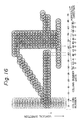
- Figure 15 shows an example of a simulated printing result of the bit map data magnified in the horizontal direction at the magnification rate three by the method of Fig. 12 (and Fig. 13)
- Figure 16 shows an example of a simulated printing result of the bit map data magnified in the horizontal direction at the magnification rate three by the method of Fig. 11 (and Fig. 9).
- the bit map font data of Fig. 2 is used as an original data
- the correspondence with a sampled series of resulting bit data indicated by "B" in Fig. 9 is shown in Fig.
- the correspondence with a sampled series of resulting bit data indicated by "F” in Fig. 13 is shown in Fig. 15.
- Fig. 15 shows an example of a simulated printing result of the bit map data magnified in the horizontal direction at the magnification rate three by the method of Fig. 11 (and Fig. 9).
- the simulated printing result of the bit map data magnified in the horizontal direction by the conventional method of Fig. 11 includes an obvious blank portion, which must be a part of a solid line in the horizontal direction, i.e., the character style magnified by the conventional method of Fig. 11, suffers obvious damage.
- the simulated printing result of the bit map data magnified in the horizontal direction by the method according to the present invention of Fig. 12 includes no blank portion, and still maintains the original character style even after the magnification, which is evident when compared with the simulated printing result of the original bit map font data of Fig. 2 shown in Fig. 3.
Landscapes
- Engineering & Computer Science (AREA)
- Physics & Mathematics (AREA)
- General Physics & Mathematics (AREA)
- Theoretical Computer Science (AREA)
- General Engineering & Computer Science (AREA)
- Multimedia (AREA)
- Controls And Circuits For Display Device (AREA)
- Dot-Matrix Printers And Others (AREA)
- Editing Of Facsimile Originals (AREA)
- Image Processing (AREA)
Applications Claiming Priority (2)
| Application Number | Priority Date | Filing Date | Title |
|---|---|---|---|
| JP63020823A JPH0832469B2 (ja) | 1988-01-29 | 1988-01-29 | ビットマップフォントの横拡大方式 |
| JP20823/88 | 1988-01-29 |
Publications (2)
| Publication Number | Publication Date |
|---|---|
| EP0326295A1 true EP0326295A1 (fr) | 1989-08-02 |
| EP0326295B1 EP0326295B1 (fr) | 1992-12-16 |
Family
ID=12037759
Family Applications (1)
| Application Number | Title | Priority Date | Filing Date |
|---|---|---|---|
| EP89300559A Expired - Lifetime EP0326295B1 (fr) | 1988-01-29 | 1989-01-20 | Méthode d'agrandissement des données sous forme d'une matrice de bits selon la direction horizontale |
Country Status (7)
| Country | Link |
|---|---|
| US (1) | US5062724A (fr) |
| EP (1) | EP0326295B1 (fr) |
| JP (1) | JPH0832469B2 (fr) |
| KR (1) | KR910008427B1 (fr) |
| CA (1) | CA1319447C (fr) |
| DE (1) | DE68903837T2 (fr) |
| ES (1) | ES2036795T3 (fr) |
Cited By (5)
| Publication number | Priority date | Publication date | Assignee | Title |
|---|---|---|---|---|
| FR2655293A1 (fr) * | 1989-12-06 | 1991-06-07 | Seikosha Kk | Procede d'impression pour une imprimante matricielle. |
| DE4039010A1 (de) * | 1989-12-06 | 1991-06-13 | Seikosha Kk | Druckverfahren zur verwendung bei einem punktdrucker |
| AU647208B2 (en) * | 1990-11-26 | 1994-03-17 | Sharp Kabushiki Kaisha | Image recording apparatus for providing high quality image |
| DE4042478C2 (de) * | 1989-12-06 | 1994-04-14 | Seikosha Kk | Druckverfahren zur Verwendung bei einem Punktdrucker |
| EP0899681A1 (fr) * | 1997-08-25 | 1999-03-03 | Lexmark International, Inc. | Procédé d'impression avec imprimante à jet d'encre utiliant une résolution horizontale accrue |
Families Citing this family (13)
| Publication number | Priority date | Publication date | Assignee | Title |
|---|---|---|---|---|
| DE3925913A1 (de) * | 1989-08-04 | 1991-02-07 | Siemens Ag | Verfahren zum ansteuern von druckelementen |
| JP3327650B2 (ja) * | 1993-04-15 | 2002-09-24 | キヤノン株式会社 | 記録装置 |
| US5559930A (en) * | 1992-08-03 | 1996-09-24 | Hewlett-Packard Company | Method for reducing pixel density along a plurality of axes of a multiple dimension image representation |
| EP0622756B1 (fr) * | 1993-04-30 | 1999-06-23 | Hewlett-Packard Company | Méthode et appareil pour imprimer une image améliorée |
| US5748798A (en) * | 1993-12-28 | 1998-05-05 | Matsushita Wlectric Ind. | Method and system for adding effects to gray scale images |
| US5483355A (en) * | 1994-03-11 | 1996-01-09 | Hewlett-Packard Co. | Pixel correctional and smoothing method |
| US5537495A (en) * | 1994-03-11 | 1996-07-16 | Hewlett-Packard Company | Pixel correction and smoothing method |
| US5440407A (en) * | 1994-03-11 | 1995-08-08 | Hewlett-Packard Company | Pixel correction and smoothing method |
| JPH07336784A (ja) * | 1994-06-08 | 1995-12-22 | Toshiba Corp | クロック同期装置 |
| US5535307A (en) * | 1994-08-16 | 1996-07-09 | Hewlett-Packard Company | Printing of variable dot sizes dependent upon image density for improved graphics |
| US6304337B1 (en) | 1998-12-21 | 2001-10-16 | Lexmark International, Inc. | Stochastic method of enlarging a visual image |
| US6115031A (en) * | 1999-04-23 | 2000-09-05 | Lexmark International, Inc. | Method of converting color values |
| JP4125501B2 (ja) * | 2001-09-07 | 2008-07-30 | 富士フイルム株式会社 | カラー画像記録方法及びカラー画像ファイリングシステム |
Citations (3)
| Publication number | Priority date | Publication date | Assignee | Title |
|---|---|---|---|---|
| GB2149165A (en) * | 1983-11-05 | 1985-06-05 | Ricoh Kk | Method of reducing characters |
| US4629342A (en) * | 1983-11-30 | 1986-12-16 | Kabushiki Kaisha Toshiba | Dot-matrix printer with pattern checking and pattern correcting means |
| EP0207788A2 (fr) * | 1985-07-03 | 1987-01-07 | Lexmark International, Inc. | Appareil et méthode pour afficher des caractères accentués par matrice de points |
Family Cites Families (3)
| Publication number | Priority date | Publication date | Assignee | Title |
|---|---|---|---|---|
| US4119383A (en) * | 1976-07-20 | 1978-10-10 | Oki Electric Industry Co., Ltd. | Method and apparatus for inserting intermediate dots in a dot matrix using a dot printer |
| US4344079A (en) * | 1980-05-02 | 1982-08-10 | Burroughs Corporation | System for matrix printing |
| DE3474933D1 (en) * | 1983-07-26 | 1988-12-08 | Oki Electric Ind Co Ltd | Printing system for a dot printer |
-
1988
- 1988-01-29 JP JP63020823A patent/JPH0832469B2/ja not_active Expired - Fee Related
-
1989
- 1989-01-19 CA CA000588706A patent/CA1319447C/fr not_active Expired - Fee Related
- 1989-01-20 EP EP89300559A patent/EP0326295B1/fr not_active Expired - Lifetime
- 1989-01-20 ES ES198989300559T patent/ES2036795T3/es not_active Expired - Lifetime
- 1989-01-20 DE DE8989300559T patent/DE68903837T2/de not_active Expired - Fee Related
- 1989-01-27 KR KR1019890000859A patent/KR910008427B1/ko not_active Expired
- 1989-01-27 US US07/302,390 patent/US5062724A/en not_active Expired - Lifetime
Patent Citations (3)
| Publication number | Priority date | Publication date | Assignee | Title |
|---|---|---|---|---|
| GB2149165A (en) * | 1983-11-05 | 1985-06-05 | Ricoh Kk | Method of reducing characters |
| US4629342A (en) * | 1983-11-30 | 1986-12-16 | Kabushiki Kaisha Toshiba | Dot-matrix printer with pattern checking and pattern correcting means |
| EP0207788A2 (fr) * | 1985-07-03 | 1987-01-07 | Lexmark International, Inc. | Appareil et méthode pour afficher des caractères accentués par matrice de points |
Cited By (16)
| Publication number | Priority date | Publication date | Assignee | Title |
|---|---|---|---|---|
| GB2244835B (en) * | 1989-12-06 | 1994-03-30 | Seikosha Kk | Printing method employing a dot printer |
| DE4042478C2 (de) * | 1989-12-06 | 1994-04-14 | Seikosha Kk | Druckverfahren zur Verwendung bei einem Punktdrucker |
| GB2239969A (en) * | 1989-12-06 | 1991-07-17 | Seikosha Kk | Printing employing a dot printer |
| FR2659902A1 (fr) * | 1989-12-06 | 1991-09-27 | Seikosha Kk | Procede d'impression pour une imprimante matricielle. |
| FR2661867A1 (fr) * | 1989-12-06 | 1991-11-15 | Seikosha Kk | Procede d'impression pour une imprimante matricielle. |
| GB2244835A (en) * | 1989-12-06 | 1991-12-11 | Seikosha Kk | Printing method employing a dot printer |
| DE4039010A1 (de) * | 1989-12-06 | 1991-06-13 | Seikosha Kk | Druckverfahren zur verwendung bei einem punktdrucker |
| US5535308A (en) * | 1989-12-06 | 1996-07-09 | Seikosha Co., Ltd. | Printing method for use with dot printer |
| FR2655293A1 (fr) * | 1989-12-06 | 1991-06-07 | Seikosha Kk | Procede d'impression pour une imprimante matricielle. |
| GB2239969B (en) * | 1989-12-06 | 1994-03-30 | Seikosha Kk | Printing system and method employing a dot printer |
| FR2703805A1 (fr) * | 1989-12-06 | 1994-10-14 | Seikosha Kk | Procédé d'impression pour une imprimante matricielle. |
| US5390290A (en) * | 1989-12-06 | 1995-02-14 | Seikosha Co., Ltd. | Printing method for use with dot printer |
| FR2727779A1 (fr) * | 1989-12-06 | 1996-06-07 | Seikosha Kk | Procede d'impression pour une imprimante matricielle |
| AU647208B2 (en) * | 1990-11-26 | 1994-03-17 | Sharp Kabushiki Kaisha | Image recording apparatus for providing high quality image |
| EP0899681A1 (fr) * | 1997-08-25 | 1999-03-03 | Lexmark International, Inc. | Procédé d'impression avec imprimante à jet d'encre utiliant une résolution horizontale accrue |
| CN1081541C (zh) * | 1997-08-25 | 2002-03-27 | 莱克斯马克国际公司 | 用喷墨打印机采用提高的水平分辨率来打印的方法 |
Also Published As
| Publication number | Publication date |
|---|---|
| CA1319447C (fr) | 1993-06-22 |
| DE68903837D1 (de) | 1993-01-28 |
| KR910008427B1 (ko) | 1991-10-15 |
| JPH0832469B2 (ja) | 1996-03-29 |
| KR890012242A (ko) | 1989-08-25 |
| US5062724A (en) | 1991-11-05 |
| DE68903837T2 (de) | 1993-04-22 |
| JPH01195063A (ja) | 1989-08-04 |
| EP0326295B1 (fr) | 1992-12-16 |
| ES2036795T3 (es) | 1993-06-01 |
Similar Documents
| Publication | Publication Date | Title |
|---|---|---|
| EP0326295B1 (fr) | Méthode d'agrandissement des données sous forme d'une matrice de bits selon la direction horizontale | |
| US5526476A (en) | Method and apparatus for generating character patterns expressed by coordinates of a coordinate system | |
| EP0323240B1 (fr) | Processeur de caractères muni de la fonction de correction de la forme des caractères matriciels | |
| US4400791A (en) | Dot matrix printer with compressed character data storage | |
| US3354816A (en) | Line printer with proportional spacing control means | |
| EP0132415B1 (fr) | Système d'impression pour une imprimante de points | |
| EP0159895B1 (fr) | Imprimante permettant l'impression des caractères en deux qualités d'impression alternatives | |
| DE69020930T2 (de) | Gerät und Verfahren zum Generieren von Musterdaten für ein Anzeige und/oder einen Drucker. | |
| JPH0429553B2 (fr) | ||
| US5199803A (en) | Method of compressing and expanding dot-matrix character | |
| US4554637A (en) | Method for reducing the redundancy of binary character sequences for matrix printing | |
| JPH01218851A (ja) | ドットマトリクス式プリンタ | |
| KR100212412B1 (ko) | 문자패턴 생성장치 | |
| EP0533049B1 (fr) | Imprimante pour imprimer des caractères gras | |
| EP0678826B1 (fr) | Imprimante série | |
| EP0415908A1 (fr) | Imprimante matricielle par points. | |
| JP3055738B2 (ja) | ドットマトリクスパターンの印字方法および装置 | |
| US5233365A (en) | Dot-matrix printer having interchangeable line head and moving head technologies | |
| GB2157865A (en) | Dot printer | |
| JPS6259674B2 (fr) | ||
| JPH0457510B2 (fr) | ||
| JPS6142634B2 (fr) | ||
| US5457774A (en) | Bit map data generation apparatus | |
| JP3077449B2 (ja) | ドットパターン変換方法およびドットパターン変換装置 | |
| KR890003283B1 (ko) | 플로팅 메카니즘을 이용한 한글 인자 방법 |
Legal Events
| Date | Code | Title | Description |
|---|---|---|---|
| PUAI | Public reference made under article 153(3) epc to a published international application that has entered the european phase |
Free format text: ORIGINAL CODE: 0009012 |
|
| AK | Designated contracting states |
Kind code of ref document: A1 Designated state(s): DE ES FR GB IT |
|
| 17P | Request for examination filed |
Effective date: 19900124 |
|
| 17Q | First examination report despatched |
Effective date: 19920327 |
|
| ITF | It: translation for a ep patent filed | ||
| GRAA | (expected) grant |
Free format text: ORIGINAL CODE: 0009210 |
|
| AK | Designated contracting states |
Kind code of ref document: B1 Designated state(s): DE ES FR GB IT |
|
| REF | Corresponds to: |
Ref document number: 68903837 Country of ref document: DE Date of ref document: 19930128 |
|
| ET | Fr: translation filed | ||
| REG | Reference to a national code |
Ref country code: ES Ref legal event code: FG2A Ref document number: 2036795 Country of ref document: ES Kind code of ref document: T3 |
|
| PLBE | No opposition filed within time limit |
Free format text: ORIGINAL CODE: 0009261 |
|
| STAA | Information on the status of an ep patent application or granted ep patent |
Free format text: STATUS: NO OPPOSITION FILED WITHIN TIME LIMIT |
|
| 26N | No opposition filed | ||
| PGFP | Annual fee paid to national office [announced via postgrant information from national office to epo] |
Ref country code: ES Payment date: 19960129 Year of fee payment: 8 |
|
| PG25 | Lapsed in a contracting state [announced via postgrant information from national office to epo] |
Ref country code: ES Free format text: LAPSE BECAUSE OF NON-PAYMENT OF DUE FEES Effective date: 19970121 |
|
| REG | Reference to a national code |
Ref country code: ES Ref legal event code: FD2A Effective date: 19990301 |
|
| REG | Reference to a national code |
Ref country code: GB Ref legal event code: IF02 |
|
| PGFP | Annual fee paid to national office [announced via postgrant information from national office to epo] |
Ref country code: FR Payment date: 20040108 Year of fee payment: 16 |
|
| PGFP | Annual fee paid to national office [announced via postgrant information from national office to epo] |
Ref country code: GB Payment date: 20040114 Year of fee payment: 16 |
|
| PGFP | Annual fee paid to national office [announced via postgrant information from national office to epo] |
Ref country code: DE Payment date: 20040129 Year of fee payment: 16 |
|
| PG25 | Lapsed in a contracting state [announced via postgrant information from national office to epo] |
Ref country code: IT Free format text: LAPSE BECAUSE OF NON-PAYMENT OF DUE FEES;WARNING: LAPSES OF ITALIAN PATENTS WITH EFFECTIVE DATE BEFORE 2007 MAY HAVE OCCURRED AT ANY TIME BEFORE 2007. THE CORRECT EFFECTIVE DATE MAY BE DIFFERENT FROM THE ONE RECORDED. Effective date: 20050120 Ref country code: GB Free format text: LAPSE BECAUSE OF NON-PAYMENT OF DUE FEES Effective date: 20050120 |
|
| PG25 | Lapsed in a contracting state [announced via postgrant information from national office to epo] |
Ref country code: DE Free format text: LAPSE BECAUSE OF NON-PAYMENT OF DUE FEES Effective date: 20050802 |
|
| GBPC | Gb: european patent ceased through non-payment of renewal fee |
Effective date: 20050120 |
|
| PG25 | Lapsed in a contracting state [announced via postgrant information from national office to epo] |
Ref country code: FR Free format text: LAPSE BECAUSE OF NON-PAYMENT OF DUE FEES Effective date: 20050930 |
|
| REG | Reference to a national code |
Ref country code: FR Ref legal event code: ST |