EP0326521A1 - Raumteiler - Google Patents
Raumteiler Download PDFInfo
- Publication number
- EP0326521A1 EP0326521A1 EP89810065A EP89810065A EP0326521A1 EP 0326521 A1 EP0326521 A1 EP 0326521A1 EP 89810065 A EP89810065 A EP 89810065A EP 89810065 A EP89810065 A EP 89810065A EP 0326521 A1 EP0326521 A1 EP 0326521A1
- Authority
- EP
- European Patent Office
- Prior art keywords
- columns
- room divider
- divider according
- cable duct
- elements
- Prior art date
- Legal status (The legal status is an assumption and is not a legal conclusion. Google has not performed a legal analysis and makes no representation as to the accuracy of the status listed.)
- Granted
Links
- 239000002184 metal Substances 0.000 claims description 4
- 238000005192 partition Methods 0.000 abstract 1
- 239000000969 carrier Substances 0.000 description 3
- 239000011358 absorbing material Substances 0.000 description 1
- 239000011324 bead Substances 0.000 description 1
- 238000000034 method Methods 0.000 description 1
- 238000000926 separation method Methods 0.000 description 1
- 239000007787 solid Substances 0.000 description 1
Images


Classifications
-
- E—FIXED CONSTRUCTIONS
- E04—BUILDING
- E04B—GENERAL BUILDING CONSTRUCTIONS; WALLS, e.g. PARTITIONS; ROOFS; FLOORS; CEILINGS; INSULATION OR OTHER PROTECTION OF BUILDINGS
- E04B2/00—Walls, e.g. partitions, for buildings; Wall construction with regard to insulation; Connections specially adapted to walls
- E04B2/74—Removable non-load-bearing partitions; Partitions with a free upper edge
- E04B2/7407—Removable non-load-bearing partitions; Partitions with a free upper edge assembled using frames with infill panels or coverings only; made-up of panels and a support structure incorporating posts
- E04B2/7416—Removable non-load-bearing partitions; Partitions with a free upper edge assembled using frames with infill panels or coverings only; made-up of panels and a support structure incorporating posts with free upper edge, e.g. for use as office space dividers
- E04B2/7433—Removable non-load-bearing partitions; Partitions with a free upper edge assembled using frames with infill panels or coverings only; made-up of panels and a support structure incorporating posts with free upper edge, e.g. for use as office space dividers with panels and support posts
-
- A—HUMAN NECESSITIES
- A47—FURNITURE; DOMESTIC ARTICLES OR APPLIANCES; COFFEE MILLS; SPICE MILLS; SUCTION CLEANERS IN GENERAL
- A47B—TABLES; DESKS; OFFICE FURNITURE; CABINETS; DRAWERS; GENERAL DETAILS OF FURNITURE
- A47B83/00—Combinations comprising two or more pieces of furniture of different kinds
- A47B83/001—Office desks or work-stations combined with other pieces of furniture, e.g. work space management systems
-
- A—HUMAN NECESSITIES
- A47—FURNITURE; DOMESTIC ARTICLES OR APPLIANCES; COFFEE MILLS; SPICE MILLS; SUCTION CLEANERS IN GENERAL
- A47B—TABLES; DESKS; OFFICE FURNITURE; CABINETS; DRAWERS; GENERAL DETAILS OF FURNITURE
- A47B2200/00—General construction of tables or desks
- A47B2200/01—Office wall with desktop function
-
- E—FIXED CONSTRUCTIONS
- E04—BUILDING
- E04B—GENERAL BUILDING CONSTRUCTIONS; WALLS, e.g. PARTITIONS; ROOFS; FLOORS; CEILINGS; INSULATION OR OTHER PROTECTION OF BUILDINGS
- E04B2/00—Walls, e.g. partitions, for buildings; Wall construction with regard to insulation; Connections specially adapted to walls
- E04B2/74—Removable non-load-bearing partitions; Partitions with a free upper edge
- E04B2002/7483—Details of furniture, e.g. tables or shelves, associated with the partitions
Definitions
- the present invention is based on the object of designing office workplaces in such a way that the desks can be relieved and nevertheless optimal access to the electronic apparatus is possible. This object is achieved by the combination of features according to claim 1.
- the cable channels in the desks are superfluous. If the desk is pushed towards the room divider, a cable can be routed directly from the cable duct of the room divider to the desk.
- all electronic devices can now be installed in cabinet elements in the room divider. Since the upper edge of the cable duct is located approximately at desk height, a work surface, e.g. for a keyboard or a screen. The connection cables can then be stowed away very easily. Only occasionally used devices are stored in a cabinet element and remain connected.
- the solution according to the invention is extremely flexible, so that the individual workplace can easily be adapted to the needs of the user and the requirements dictated by new work equipment or work processes.
- Room dividers for dividing an open-plan office into individual workplaces have been known for a long time.
- the room divider described in US Pat. No. 3,471,629 consists of wall elements which are suspended from support columns.
- a cable duct is attached to the upper edge of the wall elements.
- An electrical connection line can be routed from the floor into the cable duct or a branch line from the cable duct to the workplaces via vertical branch ducts laid in the wall elements.
- the laying of the cables is however here very complex because the plug must be removed to pull the cable through the narrow pipe ducts in the wall elements.
- the separating elements 4 can be wall elements 42, e.g. made of sound absorbing material. However, at least some of the separating elements 4 are designed as supply bodies 40, 41 for receiving office utensils, e.g. as a cabinet element 40 or drawer element 41.Cabinet and drawer elements 40, 41 have a modular structure and each consist of two side walls 43 made of sheet metal, which are screwed to the side of a shelf 44 and a rear wall 45, and a front plate 46.
- the drawer elements 41 are Front panel 46 can be pulled out horizontally, in cabinet elements 40 it can be pivoted along its upper edge and inserted in the pivoted-up position.
- the lower half 46a of the front panel can also be swiveled into a horizontal position.
- the front plates 46 are inclined slightly downwards outwards. This simplifies the locking mechanism for the foldable front panels 46, 46a wel only stops are required to hold the front panels in the closed position.
- covers 47 are fastened on the columns 1 above the elements 40, 41.
- a cable channel 2 is attached to each side of the columns 1.
- the two channels 2 are arranged at the same height apart. Its upper edge is approximately at the height of a desk 6, ie 50 cm to 80 cm from the floor. Has been particularly useful a height of 68 cm from the floor turned out.
- the cable channels 2 are detachably connected to the columns 1, for example screwed. Columns 1 and channels 2 together form a rigid, stable, stable frame that does not require wall or ceiling attachment.
- the separating elements 4 are suspended in the framework. As indicated in Fig. 2, cable strands 8 can be inserted through the end faces of the cable ducts 2, from below or from above into the cable ducts 2, in the latter case, for example, via the special separating element required at a branch, cross or kink point.
- the support column 1 consists of two tubes 11 with a circular cross section welded to one another at a distance from one another by means of round, horizontal connecting rods 10 of smaller diameter.
- a transversely projecting foot 12 is screwed onto the lower end of the tube. After loosening the screw 12a, the foot 12 can be rotated around the pipe axis. At the free end, a base plate 13 is screwed into the foot 12. It has a relatively large diameter so that the weight of the room divider is adequately distributed and soft carpets are not damaged.
- the framework consisting of columns 1 and channels 2 can be adjusted will. Due to the relatively wide protruding feet 12, a high level of stability is achieved, even if the room divider is not very branched and bent. Because the foot 12 can be rotated and locked around the pipe axis, despite its further projection, disturbances at corners or free ends of the room divider can be avoided.
- a U-shaped, solid cable duct support 14 (FIG. 5) is screwed onto each of the two pipes 11.
- the two legs 15 of the carrier 14 are horizontal.
- the vertical web 16 of the carrier 14 is milled out concavely and cylindrically and lies against the tube 11.
- the lower leg 15 has a horizontal transverse bore 17 at the free end.
- a cable duct element 20 consisting of a substantially U-shaped, laterally open profile made of sheet metal with a base plate 21, a horizontal cover plate 22 and a rear wall 23 and a flap 24.
- a U-shaped flange plate 25 is welded to the base and cover plate 21, 22 and the rear wall 23, which is screwed to the carrier 15.
- the base plate 21 is bent up to a flange 27 at its free edge for stiffening and for retaining cables.
- at least one opening 28 is stamped out, which extends from the free edge of the Flange 27 extends into the rear wall 23 approximately to the lower holding rail 26.
- the flap 24 has continuous, horizontal, triangular cross-section stiffening beads.
- a hinge block 29 with a longitudinal bore 30 and a longitudinal slot 31 is welded to the flap plate on both sides at the bottom.
- a spring-loaded hinge mandrel 32 is guided in the bore 30.
- the mandrel 32 protrudes into the bore 17 and can be withdrawn from the bore 17 by actuating a transverse pin 33 protruding through the slot 31.
- the flap 24 is thus easily removable and cables can be inserted or removed through the openings 28 without having to be looped.
- a snap element 35 serves to hold the flap 24 in the closed position.
- the separating elements 4 are supported on both sides by an L-shaped sheet carrier 50 made of sheet metal (FIG. 6).
- the lower, horizontal leg 51 of the carrier 50 has two circular segment-shaped recesses 52 for abutment on the two tubes 11.
- a projection 53 protrudes from each of these recesses 52 and, in the assembled state, in corresponding transverse bores 18 (FIG. 3) in the tubes 11 engages below one of the connecting rods 10.
- On the vertical leg 54 two fingers 55 bent over by 180 ° are formed. These fingers 55 grip one of the connecting rods 10 in the assembled state and transmit the load to this rod.
- the fingers 55 are asymmetrical and leave a free gap 56 on one side and between them, which is wider than the finger width.
- the trays 44 of cabinet elements 40 arranged directly above the cable channels 2 have a longitudinal slot 48 (FIG. 3) for the passage of cables.
- These cabinet elements are particularly suitable for accommodating electronic work equipment because their shelf 44 is at a comfortable desk height and the connecting cables can be guided directly into the cable duct via the slot 48 and one of the openings 28.
- the covers 47 are burglar-proof on the two tubes 11 of the columns 1 increases.
- rectangular openings 60 are cut out in the tubes.
- Lugs 61 of a holder 62 are snapped into the openings 60.
- the holder 62 is made of a dimensionally stable plastic. Its lower end 63 is concave cylindrical.
- a transverse web 64 of a clamping bolt 65 engages on it.
- the web 64 has a spherical surface 66 facing the end 63.
- the clamping bolt 65 has a hexagon head 67.
- the head 67 is pulled somewhat downward by the spherical surface 66, so that it clamps a cover support 69 placed on the tube 11 onto the tube 11.
- the cover carrier 69 is expediently centered on the two tubes 11, for example by an embossed depression 70 in each case.
- a securing plate 71 is placed on the cover carrier 69. This encloses the hexagonal heads 67 in a form-fitting manner.
- Carrier 69 and plate 71 have aligned through-bores through which the cover 47 is screwed down with screws 72 from below.
- the clamping bolts 65 are thus secured against rotation and the cover 47 can only be removed by loosening the screws 72, ie after opening the cabinet or drawer element 40, 41, if necessary with the appropriate key.
- the cabinet and drawer elements 40, 41 are burglar-proof, ie a possible burglary is only possible through the use of force and could not remain undetected.
- FIG. 7 shows an embodiment of the lid support 69 in the event that the column 1 is an end column.
- the cover support 69 projects symmetrically over the tubes 11 on both sides. So that the two covers 47 are aligned, securing plates 71 are placed on both sides, although only one plate 71 would be required for securing.
- the side wall 43 of the cabinet and drawer elements 40, 41 is connected to the tube 11 by means of a bayonet quick connector 75.
- the connector 75 has a round, disk-shaped head 76 with a hexagon socket for the engagement of an Allen key.
- two latches 78, 79 offset from one another by 90 ° are formed on the shaft 77 of the connector 75.
- the first bolt 78 at the free shaft end is designed to pass through the elongated hole 19 in the tube 11 and, after the connector 75 has been rotated, engages behind the inner wall of the tube 11 with a spherical contact surface 80.
- the second bolt 79 is longer than the first and slides when Turn between the tube 11 and the side wall 43.
- the opening 81 in the side wall 43 for the passage of the bolt 79 is out of round and has its greatest width in the horizontal direction.
- the supply bodies 40, 41 are therefore somewhat shorter than the clear width between adjacent ones Pillars 1. This enables the supply bodies 40, 41 to be easily installed and removed.
- the room divider described can be extremely easily adapted to changing needs, because the separating elements 4 can be quickly replaced by others without having to dismantle the framework consisting of the columns 1 and the cable ducts 2. Thanks to the high level of stability, the room divider is very easy to assemble and any room structure can be realized within the given grid. Due to the excellently developed, large possible work surface at desk height, the electronic work tools can be used optimally and the desk 6 is free of cables and equipment. Due to the modular structure of the supply bodies 40, 41, it is also possible to separate individual parts of these bodies, e.g. replace the back wall. The supply body 40, 41 can optionally be used from one of the two sides, so that the room divider can be used mutually.
- the tubes 11 of the columns 1 are in one piece in height. However, they can also be subdivided into several sections which are connected to one another in a detachable manner at the end by pipe connectors.
- the lowest separation point can be, for example, at the height of the upper edge of the cable channel 2. This training provides an even greater flexibility in the arrangement of the room divider.
Landscapes
- Engineering & Computer Science (AREA)
- Architecture (AREA)
- Physics & Mathematics (AREA)
- Electromagnetism (AREA)
- Civil Engineering (AREA)
- Structural Engineering (AREA)
- Tables And Desks Characterized By Structural Shape (AREA)
- Catching Or Destruction (AREA)
- Toys (AREA)
- Percussion Or Vibration Massage (AREA)
- Furniture Connections (AREA)
- Installation Of Indoor Wiring (AREA)
Abstract
Description
- Bei modernen Büroarbeitsplätzen müssen viele elektronische Apparate miteinander, mit dem Leitungsnetz sowie mit externen Geräten verbunden werden. Moderne Büroschreibtische haben zu diesem Zweck Kabelkanäle im Schreibtischgestell. Darin können Kabel verstaut und geführt werden, so dass die auf den Schreibtisch gestellten Apparate bequem angeschlossen werden können. Diese Lösung eignet sich gut für Arbeitsplätze, bei welchen überwiegend mit dem ganzen Instrumentarium an Apparaten gearbeitet werden muss. Werden jedoch einzelne Apparate relativ selten gebraucht, so versperren diese entweder auf dem Schreibtisch unnötig viel Platz oder sie müssen jeweils bei Bedarf hervorgeholt und angeschlossen werden, was umständlich ist.
- Der vorliegenden Erfindung liegt die Aufgabe zugrunde, Büroarbeitsplätze so zu gestalten, dass die Schreibtische entlastet werden können unt trotzdem ein optimaler Zugriff zu den elektronischen Apparaten möglich ist. Diese Aufgabe wird durch die Merkmalskombination gemäss Anspruch 1 gelöst.
- Bei der erfindungsgemässen Ausbildung sind die Kabelkanäle in den Schreibtischen überflüssig. Wenn der Schreibtisch an den Raumteiler herangeschoben wird, kann ein Kabel direkt vom Kabelkanal des Raumteilers auf das Pult geführt werden. Ausserdem können nun sämtliche elektronischen Geräte in Schrankelemente im Raumteiler eingebaut werden. Da die Oberkante des Kabelkanals annähernd auf Schreibtischhöhe angeordnet ist, kann darauf direkt eine Arbeitsfläche, z.B. für eine Tastatur oder einen Bildschirm, angeordnet werden. Die Verbindungskabel können dann sehr einfach verstaut werden. Nur gelegentlich benützte Apparate sind in einem Schrankelement verstaut und bleiben angeschlossen. Die erfindungsgemässe Lösung ist ausserordentlich flexibel, so dass der einzelne Arbeitsplatz leicht den Bedürfnissen des Benützers sowie den durch neue Arbeitsgeräte oder Arbeitsabläufe diktierten Anforderungen angepasst werden kann.
- Raumteiler zur Unterteilung eines Grossraumbüros in einzelne Arbeitsplätze sind zwar seit längerer Zeit bekannt. Der in der US-PS 3,471,629 beschriebene Raumteiler besteht aus Wandelementen, die an Tragsäulen aufgehängt sind. Auf den oberen Rand der Wandelemente ist ein Kabelkanal aufgesteckt. Ueber in den Wandelementen verlegte vertikale Zweigkanäle kann eine elektrische Anschlussleitung vom Boden her in den Kabelkanal oder eine Zweigleitung vom Kabelkanal zu den Arbeitsplätzen geführt werden. Das Verlegen der Kabel ist hier allerdings sehr aufwendig, weil zum Durchziehen der Kabel durch die engen Rohrkanäle in den Wandelementen die Stecker entfernt werden müssen.
- Nachfolgend wird ein Ausführungsbeispiel der Erfindung anhand der Zeichnung erläutert. Darin zeigt:
- Fig. 1 eine perspektivische Ansicht eines mit einem erfindungsgemässen Raumteiler unterteilten Raumes,
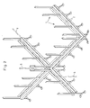
- Fig. 2 eine perspektivische Ansicht des Gerippes des Raumteilers nach Fig. 1,
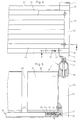
- Fig. einen Querschnitt durch einen Raumteiler nach Fig. 1,
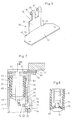
- Fig. 4 eine Seitenansicht eines Kabelkanals,
- Fig. 5 einen Querschnitt längs der Linie V - V in Fig. 4,
- Fig. 6 eine perspektivische Ansicht eines Tablarträgers,
- Fig. 7 einen Schnitt längs der Linie VII - VII in Fig. 3, und
- Fig. 8 einen Schnitt längs der Linie VIII - VIII in Fig. 7 durch den Halter.
- Der Raumteiler nach Fig. 1 ist modular auf einem Grundraster aufgebaut und besteht aus Tragsäulen 1, einem Kabelkanal 2 und Trennelementen 4. Die Trennelemente 4 können Wandelemente 42, z.B. aus schallabsorbierendem Material, sein. Mindestens einige der Trennelemente 4 sind jedoch als Versorgungskörper 40, 41 zur Aufnahme von Büroutensilien ausgebildet, z.B. als Schrankelement 40 oder Schubladenelement 41. Schrank- und Schubladenelemente 40, 41 sind modular aufgebaut und bestehen jeweils aus zwei Seitenwänden 43 aus Blech, die seitlich an einem Tablar 44 und einer Rückwand 45 festgeschraubt sind, sowie einer Frontplatte 46. Bei Schubladenelementen 41 ist die Frontplatte 46 horizontal ausziehbar, bei Schrankelementen 40 längs ihres oberen Randes schwenkbar und in der hochgeschwenkten Lage einschiebbar. Bei hohen Schrankelementen 40a, z.B. für grosse Bildschirme, ist zusätzlich die untere Hälfte 46a der Frontplatte in eine horizontale Lage abschwenkbar. Die Frontplatten 46 sind leicht nach unten aussen geneigt. Dies vereinfacht die Schliessmechanik für die klappbaren Frontplatten 46, 46a wel zum Halten der Frontplatten in der Schliessposition bloss Anschläge erforderlich sind. Als oberer Abschluss sind auf den Säulen 1 über den Elementen 40, 41 Deckel 47 befestigt.
- Aus Fig. 2 ist ersichtlich, dass beidseits der Säulen 1 je ein Kabelkanal 2 befestigt ist. Die beiden Kanäle 2 sind auf gleicher Höhe mit Abstand voneinander angeordnet. Ihre Oberkante ist annähernd auf der Höhe eines Schreibtisches 6, d.h. auf 50 cm bis 80 cm ab Boden. Als besonders zweckmässig hat sich eine Höhe von 68 cm ab Boden herausgestellt. Die Kabelkanäle 2 sind mit den Säulen 1 lösbar verbunden, z.B. verschraubt. Säulen 1 und Kanäle 2 bilden zusammen ein starres, stabiles, standfestes Gerippe, das keiner Wand- oder Deckenbefestigung bedarf. Im Gerippe sind die Trennelemente 4 eingehängt. Wie in Fig. 2 angedeutet ist, können Kabelstränge 8 durch die Stirnseiten der Kabelkanäle 2, von unten oder von oben in die Kabelkanäle 2 eingeführt werden, im letzteren Fall z.B. über das an einer Abzweig-, Kreuz- oder Abknickstelle erforderliche Sonder-Trennelement.
- In Fig. 3 ist ein Vertikalschnitt durch den Raumteiler in etwas grösserem Masstab dargestellt, wobei der besseren Uebersicht wegen die Seitenwände 43 der nur oberhalb der Kabelkanäle 2 angedeuteten Trennelemente 4 weggelassen sind. Die Tragsäule 1 besteht aus zwei im Abstand voneinander über runde, horizontale Verbindungsstangen 10 kleineren Durchmessers miteinander verschweissten Rohren 11 mit Kreisquerschnitt. Am unteren Rohrende ist ein quer abstehender Fuss 12 festgeschraubt. Nach Lösen der Schraube 12a kann der Fuss 12 um die Rohrachse gedreht werden. Am freien Ende ist in den Fuss 12 eine Standplatte 13 eingeschraubt. Sie hat einen relativ grossen Durchmesser, damit das Gewicht des Raumteilers hinreichend verteilt wird und weiche Teppichböden nicht beschädigt werden. Durch Aus- oder Einschrauben der Platten 13 kann das aus Säulen 1 und Kanälen 2 bestehende Gerippe justiert werden. Durch die relativ weit ausladenden Füsse 12 wird eine hohe Standsicherheit erreicht, auch wenn der Raumteiler wenig verzweigt und abgeknickt verlegt wird. Weil der Fuss 12 um die Rohrachse gedreht und arretiert werden kann, können trotzt seiner weiteren Ausladung Störungen an Ecken oder freien Enden des Raumteilers vermieden werden.
- An beiden Rohren 11 ist je ein U-förmiger, massiver Kabelkanalträger 14 (Fig. 5) festgeschraubt. Die beiden Schenkel 15 des Trägers 14 sind horizontal. Der vertikale Steg 16 des Trägers 14 ist konkav zylindrisch ausgefräst und liegt am Rohr 11 an. Der untere Schenkel 15 hat am freien Ende eine horizontale Querbohrung 17. Zwischen den beiden gleichgerichteten Trägern 14 benachbarter Säulen 1 sitzt ein Kabelkanalelement 20 bestehend aus einem im wesentlichen U-förmigen, seitlich offenen Profil aus Blech mit einer Bodenplatte 21, einer horizontalen Deckplatte 22 und eine Rückwand 23, sowie aus einer Klappe 24. An der Boden- und Deckplatte 21, 22 und der Rückwand 23 ist beidseits ein U-förmiges Flanschblech 25 angeschweisst, das am Träger 15 festgeschraubt ist. An der Rückwand 23 sind zwei horizontale Halteschienen 26 für elektrische Apparate, z.B. Kabelklemmen oder Steckdosen angeschweisst. Die Bodenplatte 21 ist an ihrem freien Rand zur Versteifung und zum Rückhalten von Kabeln zu einem Flansch 27 hochgebogen. In der Bodenplatte 21 ist mindestens ein Durchbruch 28 ausgestantzt, der sich vom freien Rand des Flansches 27 bis in die Rückwand 23 etwa zur unteren Halteschiene 26 erstreckt. Die Klappe 24 hat durchgehende, horizontale, im Querscnnitt dreieckförmige Versteifungssicken. Unten ist beidseits je ein Scharnierblock 29 mit einer Längsbohrung 30 und einem Längsschlitz 31 am Klappenblech angeschweisst. In der Bohrung 30 ist ein federbelasteter Scharnierdorn 32 geführt. Der Dorn 32 ragt in die Bohrung 17 und kann durch Betätigen eines durch den Schlitz 31 ragenden Querstiftes 33 aus der Bohrung 17 zurückgezogen werden. Damit ist die Klappe 24 leicht entfernbar und Kabel können durch die Durchbrüche 28 ein oder ausgeführt werden, ohne dass sie geschlauft werden müssen. Für den Fall, dass Kabel nach vorn aus dem Kabelkanal 2 austreten sollen, sind am freien Rand der Klappe 24 Kabeldurchführungsöffnungen 34 ausgespart, die auch als Griff zum Oeffnen der Klappe 24 dienen. Zum Halten der Klappe 24 in der geschlossenen Stellung dient ein Schnappelement 35.
- Die Trennelemente 4 werden beidseitig durch einen L-förmig gebogenen Tablarträger 50 aus Blech getragen (Fig. 6). Der untere, horizontale Schenkel 51 des Trägers 50 hat zwei kreissegmentförmige Ausnehmungen 52 zur Anlage an den beiden Rohren 11. Von jeder dieser Ausnehmungen 52 steht ein Vorsprung 53 ab, der im montierten Zustand in entsprechende Querbohrungen 18 (Fig. 3) in den Rohren 11 unterhalb einer der Verbindungsstangen 10 eingreift. Am vertikalen Schenkel 54 sind zwei um 180° umgebogene Finger 55 angeformt. Diese Finger 55 umgreifen im montierten Zustand eine der Verbindungsstangen 10 und übertragen die Last auf diese Stange. Die Finger 55 sind asymmetrisch ausgebildet und lassen auf der einen Seite und zwischen sich je eine freie Lücke 56 offen, die breiter ist als die Fingerbreite. Dadurch können an der gleichen Verbindungsstange 10 zwei identische Träger 50 spiegelbildlich zur Mittelebene der Säulen 1 eingehängt werden. Die Finger 55 des einen Trägers passen in die Lücken 56 des andern. Wenn die Träger 50 eingesetzt und ein Tablar 44 auf die Träger 50 ausgesetzt ist, sind die Träger 50 fixiert und können nach keiner Seite bewegen oder schwenken. Die eingesetzten Elemente 4 werden hierauf noch durch Bajonettverschlüsse fixiert, welche die Seitenwände 43 durchgreifen und in Langlöcher 19 (Fig. 3) in den Rohren 11 eingreifen.
- Die unmittelbar über den Kabelkanälen 2 angeordneten Tablare 44 von Schrankelementen 40 haben einen Längsschlitz 48 (Fig. 3) zur Durchführung von Kabeln. Diese Schrankelemente sind besonders geeignet für die Aufnahme elektronischer Arbeitsgeräte, weil ihr Tablar 44 auf bequemer Schreibtischhöhe ist und die Anschlusskabel über den Schlitz 48 und einen der Durchbrüche 28 direkt in den Kabelkanal geführt werden können.
- Wie in Fig. 7 und 8 veranschaulicht ist, sind die Deckel 47 einbruchsicher auf den beiden Rohren 11 der Säulen 1 befe stigt. Am oberen Ende sind in den Rohren 11 rechteckige Oeffnungen 60 ausgestantzt. In die Oeffnungen 60 sind Nasen 61 eines Halters 62 eingeschnappt. Der Halter 62 besteht aus einem formbeständigen Kunststoff. Sein unteres Stirnende 63 ist konkav zylindrisch. An ihm greift ein Quersteg 64 eines Spannbolzens 65 an. Der Steg 64 hat dem Stirnende 63 zugewandt eine sphärische Fläche 66. Am oberen Ende hat der Spannbolzen 65 einen Sechskantkopf 67. Beim Einführen wird der Steg 64 durch ein axiales Langloch 68 im Halter 62 gesteckt und dann um 90° gedreht. Durch die sphärische Fläche 66 wird dabei der Kopf 67 etwas nach unten gezogen, so dass er einen auf das Rohr 11 aufgesetzten Deckelträger 69 auf dem Rohr 11 festspannt. Zweckmässig ist der Deckelträger 69 auf den beiden Rohren 11 zentriert, z.B. durch je eine eingeprägte Ansenkung 70. Auf den Deckelträger 69 wird eine Sicherungsplatte 71 aufgelegt. Diese umgreift formschlüssig die Sechskantköpfe 67. Träger 69 und Platte 71 haben fluchtende Durchgangsbohrungen, durch welche der Deckel 47 von unten mit Schrauben 72 festgeschraubt wird. Die Spannbolzen 65 sind damit gegen Verdrehen gesichert und der Deckel 47 kann nur durch Lösen der Schrauben 72 entfernt werden, d.h. nach dem Oeffnen des Schrank- oder Schubladenelementes 40, 41 gegebenenfalls mit dem passenden Schlüssel. Dadurch sind die Schrank- und Schubladenelemente 40,41 einbruchsicher, d.h. ein allfälliger Einbruch ist nur durch Gewaltanwendung möglich und könnte nicht unentdeckt bleiben.
- In Fig. 7 ist eine Ausführungsform des Deckelträgers 69 dargestellt für den Fall, dass die Säule 1 eine Endsäule ist. Schliessen hingegen beidseitig an die Säule 1 Deckel 47 an, so überragt der Deckelträger 69 die Rohre 11 beidseits symmetrisch. Damit die beiden Deckel 47 fluchten, werden auf beiden Seiten Sicherungsplatten 71 aufgelegt, obwohl zur Sicherung nur eine Platte 71 erforderlich wäre.
- Wie aus Fig. 7 ersichtlich ist, ist die Seitenwand 43 der Schrank- und Schubladenelemente 40, 41 mittels eines Bajonett-Schnellverbinders 75 mit dem Rohr 11 verbunden. Der Verbinder 75 hat einen runden, scheibenförmigen Kopf 76 mit einem Innensechskant zum Eingriff eines Inbusschlüssels. Am Schaft 77 des Verbinders 75 sind zwei um 90° gegeneinander versetzte Riegel 78, 79 angeformt. Der erste Riegel 78 am freien Schaftende ist zum Durchtritt durch das Langloch 19 im Rohr 11 ausgebildet und hintergreift nach dem Drehen des Verbinders 75 mit einer sphärischen Anlagefläche 80 die Innenwand des Rohres 11. Der zweite Riegel 79 ist länger als der erste und schiebt sich beim Drehen zwischen das Rohr 11 und die Seitenwand 43. Die Oeffnung 81 in der Seitenwand 43 für den Durchtritt des Riegels 79 ist unrund und hat ihre grösste Weite in horizontaler Richtung. Durch diese Ausbildung des Verbinders 75 besteht Abstand zwischen der Säule 1 und der Seitenwand 43. Die Versorgungskörper 40, 41 sind also etwas kürzer als die lichte Weite zwischen benachbarten Säulen 1. Dadurch wird ein einfacher Ein- und Ausbau der Versorgungskörper 40, 41 ermöglicht.
- Der beschriebene Raumteiler kann ausserordentlich leicht an wechselnde Bedürfnisse angepasst werden, weil die Trennelemente 4 rasch gegen andere ausgetauscht werden können, ohne dass dazu das aus den Säulen 1 und den Kabelkanälen 2 bestehende Gerippe demontiert werden muss. Dank der grossen Standsicherheit ist der Raumteiler sehr einfach zu montieren, und es können innerhalb des gegebenen Rasters beliebige Raumgliederungen verwirklicht werden. Durch die vorzüglich erschlossene, grosse mögliche Arbeitsfläche auf Schreibtischhöhe können die elektronischen Arbeitsgeräte optimal eingesetzt werden und der Schreibtisch 6 wird frei von Kabeln und Gerätschaften. Durch den modularen Aufbau der Versorungskörper 40, 41 ist es möglich, von diesen Körpern auch Einzelteile, z.B. die Rückwand auszutauschen. Die Versorgungskörper 40, 41 können wahlweise von einer der beiden Seiten eingesetzt werden, sodass der Raumteiler wechselseitig benützbar ist.
- Im dargestellten Ausführungsbeispiel sind die Rohre 11 der Säulen 1 in der Höhe einstückig. Sie können jedoch auch in mehrere Teilstücke unterteilt sein, die durch Rohrverbinder stirnseitig lösbar miteinander verbunden sind. Die unterste Trennstelle kann z.B. auf der Höhe der Oberkante des Kabel kanals 2 sein. Durch diese Ausbildung wird eine noch grössere Flexibilität in der Aufstellung des Raumteilers erreicht.
Claims (13)
Priority Applications (1)
| Application Number | Priority Date | Filing Date | Title |
|---|---|---|---|
| AT89810065T ATE70330T1 (de) | 1988-01-28 | 1989-01-25 | Raumteiler. |
Applications Claiming Priority (2)
| Application Number | Priority Date | Filing Date | Title |
|---|---|---|---|
| CH290/88A CH671597A5 (de) | 1988-01-28 | 1988-01-28 | |
| CH290/88 | 1988-01-28 |
Publications (2)
| Publication Number | Publication Date |
|---|---|
| EP0326521A1 true EP0326521A1 (de) | 1989-08-02 |
| EP0326521B1 EP0326521B1 (de) | 1991-12-11 |
Family
ID=4183624
Family Applications (1)
| Application Number | Title | Priority Date | Filing Date |
|---|---|---|---|
| EP89810065A Expired - Lifetime EP0326521B1 (de) | 1988-01-28 | 1989-01-25 | Raumteiler |
Country Status (8)
| Country | Link |
|---|---|
| US (1) | US4932177A (de) |
| EP (1) | EP0326521B1 (de) |
| AT (1) | ATE70330T1 (de) |
| CA (1) | CA1309226C (de) |
| CH (1) | CH671597A5 (de) |
| DE (1) | DE58900538D1 (de) |
| ES (1) | ES2027830T3 (de) |
| ZA (1) | ZA89676B (de) |
Cited By (2)
| Publication number | Priority date | Publication date | Assignee | Title |
|---|---|---|---|---|
| EP0505592A1 (de) * | 1991-03-26 | 1992-09-30 | Isaria Werbetechnik Gmbh | Einrichtung zur Bildung teilabgeschirmter Arbeitsplätze |
| WO1993002260A1 (en) * | 1991-07-19 | 1993-02-04 | Teknion Furniture Systems | Monitor screen for an office panel |
Families Citing this family (32)
| Publication number | Priority date | Publication date | Assignee | Title |
|---|---|---|---|---|
| US5394658A (en) | 1988-07-29 | 1995-03-07 | Schreiner; Charles P. | Free standing modular furniture and wall system |
| US6497075B1 (en) | 1988-07-29 | 2002-12-24 | Herman Miller Inc. | Free standing modular architectural beam system |
| US5778612A (en) * | 1990-11-28 | 1998-07-14 | Kissinger; Terrance G. | Partition panel containing data processing or communications equipment |
| US5873205A (en) * | 1990-11-28 | 1999-02-23 | Advantage Office Systems, Llc | Privacy panel for use with open office furniture systems |
| US5209035A (en) | 1991-01-10 | 1993-05-11 | Steelcase Inc. | Utility panel system |
| USD357597S (en) | 1992-01-24 | 1995-04-25 | Urs Bachmann | Room divider |
| IL105542A (en) * | 1992-05-04 | 1995-12-31 | Teknion Furniture Systems | Desktop system |
| US6088981A (en) * | 1993-07-23 | 2000-07-18 | Office Specialty Inc. | Recessed cover for partition |
| US5881518A (en) * | 1993-10-15 | 1999-03-16 | Hollanding Inc. | Modular partition system |
| US5638650A (en) * | 1993-07-23 | 1997-06-17 | Hollanding Inc. | Retaining clips for office furniture partition |
| CA2101190C (en) * | 1993-10-15 | 2005-03-15 | Hollanding Inc. | Modular office furniture partition |
| US6128873A (en) | 1994-12-30 | 2000-10-10 | Steelcase Development Inc. | Integrated prefabricated furniture system for fitting-out open plan building space |
| US5746034B1 (en) | 1994-12-30 | 2000-10-17 | Steelcase Inc | Partition system |
| CA2257098C (en) * | 1996-06-04 | 2007-04-24 | Nova-Link Limited | Beam-type office furniture system and modules |
| US5852904A (en) * | 1996-08-05 | 1998-12-29 | Haworth, Inc. | Panel arrangement |
| US5943834A (en) * | 1996-12-17 | 1999-08-31 | Steelcase Inc. | Partition construction |
| US6910306B2 (en) * | 1996-12-24 | 2005-06-28 | Steelcase Development Corporation | Knock-down portable partition system |
| US6546684B2 (en) | 1998-04-15 | 2003-04-15 | Steelcase Development Corporation | Partition panel |
| US6301846B1 (en) | 1996-12-24 | 2001-10-16 | Steelcase Development Inc. | Knock-down portable partition system |
| US5899035A (en) * | 1997-05-15 | 1999-05-04 | Steelcase, Inc. | Knock-down portable partition system |
| US5836112C1 (en) * | 1997-05-09 | 2001-05-15 | Steelcase Inc | Partition system including transaction top |
| US6167664B1 (en) | 1997-05-28 | 2001-01-02 | Knoll, Inc. | Hybrid office panel construction for a modular office furniture system |
| US5901513A (en) * | 1997-06-04 | 1999-05-11 | Rosemount Office Systems, Inc. | Lay in cable channel for modular office systems |
| CA2207344C (en) * | 1997-06-09 | 2002-07-23 | Nova-Link Limited | Beam-type work station improvements |
| US6213191B1 (en) | 1999-01-29 | 2001-04-10 | Steelcase Development Inc. | Screen |
| US6711871B2 (en) | 2000-05-03 | 2004-03-30 | Herman Miller, Inc. | Wall panel with off-module components |
| CA2343861C (en) * | 2001-04-12 | 2008-08-05 | Tk Canada Limited | Workstation system |
| US20030226323A1 (en) * | 2002-06-07 | 2003-12-11 | Travez Jose V. | Structure having preinstalled utilities and amenities |
| US7677182B2 (en) | 2004-05-27 | 2010-03-16 | Steelcase Development Corporation | Two person work environment |
| TWI362442B (en) * | 2009-04-15 | 2012-04-21 | Univ Nat Taiwan Science Tech | Movable office screen system |
| US8844210B2 (en) * | 2011-01-04 | 2014-09-30 | Kimball International, Inc. | Upmount overhead brackets for office partition systems |
| TR2022002319A2 (tr) * | 2022-02-21 | 2022-03-21 | Nurol Teknoloji Sanayi Ve Madencilik Ticaret Anonim Sirketi | Modüler mobi̇l bali̇sti̇k kalkan si̇stemi̇ |
Citations (3)
| Publication number | Priority date | Publication date | Assignee | Title |
|---|---|---|---|---|
| EP0006707A1 (de) * | 1978-06-12 | 1980-01-09 | Hauserman Limited | System zur Unterteilung eines Stockwerkraumes in mehrere Arbeitzonen |
| EP0027001A2 (de) * | 1979-10-03 | 1981-04-15 | Hauserman Limited | Raumeinteilungssystem |
| EP0125869A2 (de) * | 1983-05-11 | 1984-11-21 | Mines And West Limited | Arbeitstisch, z.B. Schreibtisch |
Family Cites Families (4)
| Publication number | Priority date | Publication date | Assignee | Title |
|---|---|---|---|---|
| US3209869A (en) * | 1961-09-12 | 1965-10-05 | Andrew B Hammitt | Partition assembly |
| US3289368A (en) * | 1964-02-06 | 1966-12-06 | Interstate Ind Inc | Modular partition structure |
| US3844079A (en) * | 1973-09-28 | 1974-10-29 | Steelcase Inc | Support system for partitions |
| US4771583A (en) * | 1979-10-03 | 1988-09-20 | Hauserman, Inc. | Space divider system |
-
1988
- 1988-01-28 CH CH290/88A patent/CH671597A5/de not_active IP Right Cessation
-
1989
- 1989-01-25 EP EP89810065A patent/EP0326521B1/de not_active Expired - Lifetime
- 1989-01-25 DE DE8989810065T patent/DE58900538D1/de not_active Expired - Fee Related
- 1989-01-25 AT AT89810065T patent/ATE70330T1/de not_active IP Right Cessation
- 1989-01-25 ES ES198989810065T patent/ES2027830T3/es not_active Expired - Lifetime
- 1989-01-27 ZA ZA89676A patent/ZA89676B/xx unknown
- 1989-01-27 CA CA000589399A patent/CA1309226C/en not_active Expired - Fee Related
- 1989-01-27 US US07/302,807 patent/US4932177A/en not_active Expired - Fee Related
Patent Citations (3)
| Publication number | Priority date | Publication date | Assignee | Title |
|---|---|---|---|---|
| EP0006707A1 (de) * | 1978-06-12 | 1980-01-09 | Hauserman Limited | System zur Unterteilung eines Stockwerkraumes in mehrere Arbeitzonen |
| EP0027001A2 (de) * | 1979-10-03 | 1981-04-15 | Hauserman Limited | Raumeinteilungssystem |
| EP0125869A2 (de) * | 1983-05-11 | 1984-11-21 | Mines And West Limited | Arbeitstisch, z.B. Schreibtisch |
Cited By (2)
| Publication number | Priority date | Publication date | Assignee | Title |
|---|---|---|---|---|
| EP0505592A1 (de) * | 1991-03-26 | 1992-09-30 | Isaria Werbetechnik Gmbh | Einrichtung zur Bildung teilabgeschirmter Arbeitsplätze |
| WO1993002260A1 (en) * | 1991-07-19 | 1993-02-04 | Teknion Furniture Systems | Monitor screen for an office panel |
Also Published As
| Publication number | Publication date |
|---|---|
| EP0326521B1 (de) | 1991-12-11 |
| ZA89676B (en) | 1989-10-25 |
| US4932177A (en) | 1990-06-12 |
| CH671597A5 (de) | 1989-09-15 |
| ATE70330T1 (de) | 1991-12-15 |
| DE58900538D1 (de) | 1992-01-23 |
| ES2027830T3 (es) | 1992-06-16 |
| CA1309226C (en) | 1992-10-27 |
Similar Documents
| Publication | Publication Date | Title |
|---|---|---|
| EP0326521B1 (de) | Raumteiler | |
| DE69316247T2 (de) | Arbeitsraumtrennwandsystem | |
| DE3588157T2 (de) | Arbeitsraumeinteilungssystem | |
| WO1994016597A1 (de) | Arbeitsmöbel | |
| DE2731514A1 (de) | Trage- und haltestruktur fuer das zusammensetzen von modulelementen | |
| EP0901332A1 (de) | Modulares inneneinrichtungssystem | |
| EP0307620A1 (de) | Arbeitstisch | |
| DE2844396C3 (de) | Schiebetürschrank | |
| DE3916095C2 (de) | ||
| DE19614370C1 (de) | Laborarbeitsplatz | |
| WO2022063564A1 (de) | Möbeleckelement | |
| WO2006029895A1 (de) | Schreibtischsystem bzw. arbeitsplatzmöbel | |
| DE8432766U1 (de) | Bausatz für Montagevorrichtungen für elektrische Schalt- oder Verteilerschränke | |
| DE102009020726A1 (de) | Versorgungssystem zum Bereitstellen einer Medienversorgung | |
| DE19647781C2 (de) | Montageeinheit mit einer Montageschiene | |
| DE2643832C2 (de) | ||
| DE20121189U1 (de) | Einrichtung zum Installieren von Versorgungsleitungen | |
| DE4132387A1 (de) | Traganordnung fuer elektrische geraete | |
| DE9410031U1 (de) | Unterdecke für Gebäuderäume | |
| DE19801496C1 (de) | Arbeitsmöbel | |
| DE60315580T2 (de) | Labormöbel-Konstruktionssystem | |
| DE3934138A1 (de) | Bildschirmarbeitsplatz | |
| DE2721077C3 (de) | Kücheneinrichtung aus vorgefertigten Elementen | |
| DE9017221U1 (de) | Laboreinrichtungssystem | |
| DE19811713A1 (de) | Schaltschrank |
Legal Events
| Date | Code | Title | Description |
|---|---|---|---|
| PUAI | Public reference made under article 153(3) epc to a published international application that has entered the european phase |
Free format text: ORIGINAL CODE: 0009012 |
|
| AK | Designated contracting states |
Kind code of ref document: A1 Designated state(s): AT BE CH DE ES FR GB IT LI NL SE |
|
| 17P | Request for examination filed |
Effective date: 19890706 |
|
| 17Q | First examination report despatched |
Effective date: 19901011 |
|
| GRAA | (expected) grant |
Free format text: ORIGINAL CODE: 0009210 |
|
| AK | Designated contracting states |
Kind code of ref document: B1 Designated state(s): AT BE CH DE ES FR GB IT LI NL SE |
|
| REF | Corresponds to: |
Ref document number: 70330 Country of ref document: AT Date of ref document: 19911215 Kind code of ref document: T |
|
| ITF | It: translation for a ep patent filed | ||
| REF | Corresponds to: |
Ref document number: 58900538 Country of ref document: DE Date of ref document: 19920123 |
|
| PGFP | Annual fee paid to national office [announced via postgrant information from national office to epo] |
Ref country code: NL Payment date: 19920131 Year of fee payment: 4 |
|
| ET | Fr: translation filed | ||
| GBT | Gb: translation of ep patent filed (gb section 77(6)(a)/1977) | ||
| REG | Reference to a national code |
Ref country code: ES Ref legal event code: FG2A Ref document number: 2027830 Country of ref document: ES Kind code of ref document: T3 |
|
| PLBE | No opposition filed within time limit |
Free format text: ORIGINAL CODE: 0009261 |
|
| STAA | Information on the status of an ep patent application or granted ep patent |
Free format text: STATUS: NO OPPOSITION FILED WITHIN TIME LIMIT |
|
| 26N | No opposition filed | ||
| PGFP | Annual fee paid to national office [announced via postgrant information from national office to epo] |
Ref country code: FR Payment date: 19930114 Year of fee payment: 5 Ref country code: AT Payment date: 19930114 Year of fee payment: 5 |
|
| PGFP | Annual fee paid to national office [announced via postgrant information from national office to epo] |
Ref country code: SE Payment date: 19930120 Year of fee payment: 5 |
|
| PGFP | Annual fee paid to national office [announced via postgrant information from national office to epo] |
Ref country code: BE Payment date: 19930126 Year of fee payment: 5 |
|
| PGFP | Annual fee paid to national office [announced via postgrant information from national office to epo] |
Ref country code: ES Payment date: 19930209 Year of fee payment: 5 |
|
| PG25 | Lapsed in a contracting state [announced via postgrant information from national office to epo] |
Ref country code: NL Effective date: 19930801 |
|
| NLV4 | Nl: lapsed or anulled due to non-payment of the annual fee | ||
| PGFP | Annual fee paid to national office [announced via postgrant information from national office to epo] |
Ref country code: GB Payment date: 19931210 Year of fee payment: 6 |
|
| PG25 | Lapsed in a contracting state [announced via postgrant information from national office to epo] |
Ref country code: AT Effective date: 19940125 |
|
| PG25 | Lapsed in a contracting state [announced via postgrant information from national office to epo] |
Ref country code: SE Effective date: 19940126 Ref country code: ES Free format text: LAPSE BECAUSE OF NON-PAYMENT OF DUE FEES Effective date: 19940126 |
|
| PG25 | Lapsed in a contracting state [announced via postgrant information from national office to epo] |
Ref country code: BE Effective date: 19940131 |
|
| BERE | Be: lapsed |
Owner name: EMBRU-WERKE MANTEL & CIE Effective date: 19940131 |
|
| PG25 | Lapsed in a contracting state [announced via postgrant information from national office to epo] |
Ref country code: FR Effective date: 19940930 |
|
| REG | Reference to a national code |
Ref country code: FR Ref legal event code: ST |
|
| PG25 | Lapsed in a contracting state [announced via postgrant information from national office to epo] |
Ref country code: GB Effective date: 19950125 |
|
| EUG | Se: european patent has lapsed |
Ref document number: 89810065.6 Effective date: 19940810 |
|
| GBPC | Gb: european patent ceased through non-payment of renewal fee |
Effective date: 19950125 |
|
| REG | Reference to a national code |
Ref country code: CH Ref legal event code: NV Representative=s name: PATENTANWALTS-BUREAU ISLER AG |
|
| PGFP | Annual fee paid to national office [announced via postgrant information from national office to epo] |
Ref country code: CH Payment date: 20011119 Year of fee payment: 14 |
|
| PGFP | Annual fee paid to national office [announced via postgrant information from national office to epo] |
Ref country code: DE Payment date: 20011219 Year of fee payment: 14 |
|
| PG25 | Lapsed in a contracting state [announced via postgrant information from national office to epo] |
Ref country code: LI Free format text: LAPSE BECAUSE OF NON-PAYMENT OF DUE FEES Effective date: 20030131 Ref country code: CH Free format text: LAPSE BECAUSE OF NON-PAYMENT OF DUE FEES Effective date: 20030131 |
|
| PG25 | Lapsed in a contracting state [announced via postgrant information from national office to epo] |
Ref country code: DE Free format text: LAPSE BECAUSE OF NON-PAYMENT OF DUE FEES Effective date: 20030801 |
|
| REG | Reference to a national code |
Ref country code: CH Ref legal event code: PL |
|
| REG | Reference to a national code |
Ref country code: ES Ref legal event code: FD2A Effective date: 20030922 |
|
| PG25 | Lapsed in a contracting state [announced via postgrant information from national office to epo] |
Ref country code: IT Free format text: LAPSE BECAUSE OF NON-PAYMENT OF DUE FEES;WARNING: LAPSES OF ITALIAN PATENTS WITH EFFECTIVE DATE BEFORE 2007 MAY HAVE OCCURRED AT ANY TIME BEFORE 2007. THE CORRECT EFFECTIVE DATE MAY BE DIFFERENT FROM THE ONE RECORDED. Effective date: 20050125 |