EP0326636A1 - Dispositif d'alimentation en produits à peser pour balances de remplissage - Google Patents
Dispositif d'alimentation en produits à peser pour balances de remplissage Download PDFInfo
- Publication number
- EP0326636A1 EP0326636A1 EP88101605A EP88101605A EP0326636A1 EP 0326636 A1 EP0326636 A1 EP 0326636A1 EP 88101605 A EP88101605 A EP 88101605A EP 88101605 A EP88101605 A EP 88101605A EP 0326636 A1 EP0326636 A1 EP 0326636A1
- Authority
- EP
- European Patent Office
- Prior art keywords
- weighing
- container
- preliminary
- goods
- containers
- Prior art date
- Legal status (The legal status is an assumption and is not a legal conclusion. Google has not performed a legal analysis and makes no representation as to the accuracy of the status listed.)
- Granted
Links
Images

Classifications
-
- G—PHYSICS
- G01—MEASURING; TESTING
- G01G—WEIGHING
- G01G19/00—Weighing apparatus or methods adapted for special purposes not provided for in the preceding groups
- G01G19/387—Weighing apparatus or methods adapted for special purposes not provided for in the preceding groups for combinatorial weighing, i.e. selecting a combination of articles whose total weight or number is closest to a desired value
- G01G19/393—Weighing apparatus or methods adapted for special purposes not provided for in the preceding groups for combinatorial weighing, i.e. selecting a combination of articles whose total weight or number is closest to a desired value using two or more weighing units
-
- G—PHYSICS
- G01—MEASURING; TESTING
- G01G—WEIGHING
- G01G13/00—Weighing apparatus with automatic feed or discharge for weighing-out batches of material
- G01G13/02—Means for automatically loading weigh pans or other receptacles, e.g. disposable containers, under control of the weighing mechanism
- G01G13/04—Means for automatically loading weigh pans or other receptacles, e.g. disposable containers, under control of the weighing mechanism involving dribble-feed means controlled by the weighing mechanism to top up the receptacle to the target weight
- G01G13/06—Means for automatically loading weigh pans or other receptacles, e.g. disposable containers, under control of the weighing mechanism involving dribble-feed means controlled by the weighing mechanism to top up the receptacle to the target weight wherein the main feed is effected by gravity from a hopper or chute
Definitions
- the invention relates to a feed device for weighing goods on filling scales, preferably on combination combination filling scales.
- Filling scales of this type have a conveying element for transferring the weighing goods from a storage container to a central distribution device, often in the form of an oscillating conveyor trough.
- a central distribution device often in the form of an oscillating conveyor trough.
- Several metering troughs are connected to the distribution device, which transfer the goods to be weighed into the preliminary container and, after being called up, into the actual weighing container.
- the weighing containers are combined with electrical load cells, the measurement result of which is passed on to a central processing unit, from where the signal to open the actual weighing container in a funnel is given to all weighing containers whose total weight comes closest to the target weight desired.
- Such a device is shown and described for example in DE-PS 31 11 811.
- This known design of a feed device for partial quantity combination filling scales has the disadvantage that fragile goods that are sensitive to breakage and / or easily damaged on the surface, such as thin biscuits, filled thin-shelled candies, chocolate-coated confectionery and similar items, are handed over between the individual stations of the Feeder is damaged or even breaks, because the transfer between the individual stations at different points occurs in free fall.
- fragile goods that are sensitive to breakage and / or easily damaged on the surface, such as thin biscuits, filled thin-shelled candies, chocolate-coated confectionery and similar items, are handed over between the individual stations of the Feeder is damaged or even breaks, because the transfer between the individual stations at different points occurs in free fall.
- the items of the goods to be weighed fall directly from the conveyor from the storage container onto the conical distributor plate, from where they reach the various metering troughs.
- the transfer from the feed troughs to the pre-container also takes place in free fall in the previously known construction; likewise the transfer from the preliminary container after its opening into the actual weighing container and again from this into the funnel, which directs the selected partial quantities to the filling station.
- a feed device which is characterized in that at the outlet end of the metering channel in the conveying direction inclined downward and lockable with a flap slides are provided and that Pre-containers of each weighing unit are designed as swivel containers, which can be pivoted in alignment about an axis between a filling position with the slide and an emptying position with an inclined bottom of the weighing container.
- the idea of the invention consists essentially in making the preliminary container arranged in a fixed manner above the weighing container in known constructions and converting it into part of the conveying elements in the form of a trough which cooperates with the metering trough cooperating with the conical distributor plate.
- This cooperation is further improved in the sense of the task according to the invention in that the metering channel itself is provided with a slide which is designed and arranged such that the preliminary container designed as a pivoting container swings back and forth between the actual weighing container and the slide interacting with the metering channel can be.
- the transfer of the goods to be weighed from the actual weighing container into the funnel arranged below is also improved. This is achieved in that the fixed sloping bottom of the weighing container is approximately aligned with the conical inner cylinder wall of the funnel, so that when the bottom flap of the weighing container is opened, the goods to be weighed do not fall into the funnel, but can slide into the funnel along the common inclined plane .
- a known feed device according to the preamble of claim 1 is to be mentioned in the introduction.
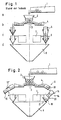
- Such a feed device is shown, for example, in the weighing machine according to FIG. 1 of DE-PS 31 11 811. Compared to the representation in the cited patent specification, the representation of FIG. 1 is somewhat more schematized.
- the known feed device contains a conveyor element in the form of a vibrating conveyor trough 1, from which the weighing goods originating from the storage container, which is shown in the form of small balls in the drawing, reaches the conical distributor plate 3 in free fall through a funnel-shaped tube 2.
- the goods to be weighed are passed radially from this distributor plate to a plurality of metering troughs 4 and fall into the preliminary container 5 at the end of these metering troughs.
- the preliminary container 5 shown on the left in FIG. 1 is shown with closed flaps, so that the goods to be weighed collect in the preliminary container 5.
- the flaps of the preliminary container 5 are open, so that the goods to be weighed can fall into the actual weighing container 6.
- the weight of the articles accumulated in the weighing container 6 is registered by the weighing cell 7 and from there fed to a central processing unit (not shown in the drawing), where the results are evaluated in a known manner.
- the computer registers the weights determined by the individual weighing units and compares them with one another. Those partial quantities are determined whose total weight best corresponds to the specified target weight, whereupon the flaps controlled by the computer are opened and the test quantities belonging to the determined combination are discharged together into the collecting funnel arranged below the weighing units.
- FIG. 2 The embodiment of a feed device according to the invention shown in FIG. 2 allows the described To largely eliminate disadvantages by redesigning the transfer devices at three points compared to the previously known construction so that the free fall leading to breakage or damage to the weighing sample is avoided and the weighing sample is transported gently.
- FIG. 2 the entrance area up to the conical distributor plate 3 is essentially unchanged. You can also arrange the vibrating conveyor trough so that its outlet opening lies close to the funnel-shaped tube 2 in order to achieve the smoothest possible transition from the trough 1 to the distributor plate 3 in this area.
- the same parts in FIGS. 1, 2 and 3 are provided with the same reference numbers.
- slides 9 are arranged at a certain adjustable angle which is inclined downwards in the conveying direction.
- These slides 9 each have a flap 10 at their ends, which can be pivoted about the pivot axis 11 from the closed position shown in FIG. 3 to an open position.
- the closed position is shown in Fig. 2 on the right side and the open position on the left side.
- the flap 10 is moved via an actuating member 12 in the form of a pneumatic or hydraulic cylinder, a rotary magnet or another known device which acts on the pivoting lever 13.
- the pre-container 14 is designed as a swivel container, which about the axis 15 from the in Fig. 2 left in the right in Fig. 2 position is pivotable. 3, the swivel container 14 is in the filling position according to the left representation in FIG. 2.
- the pre-container 14 can be pivoted from the filling position into the emptying position via an actuating member 16, which acts on the pivoting lever 17, which is firmly connected to the pivoting container and pivots the pivoting container 14 downward in FIG. 3 when the organ 16 is actuated accordingly, so that the bottom 18 of the swivel container 14 comes into contact with the fixed bottom 19 of the weighing container 20.
- the opening and closing of the flap 10 and the pivoting movement of the container 14 are carried out synchronously and controlled by the computer of the combination filling scale in an adjustable time cycle.
- the flap 10 is controlled so that it is only closed when the swiveling reservoir 14 adjoining the chute 9 is being pivoted or is in its emptying position according to FIG. 2, right side.
- the swivel container 14 does not have a bottom flap for emptying the goods to be weighed into the weighing container 20. It is emptied into the weighing container 20 only by pivoting about the axis 15.
- the flap 21 of the weighing container 20 can be rotated about the pivot axis 22.
- the actuation takes place via similar organs to the slide 9 or the swivel container 14, which are not shown in FIG. 3, however.
- the movement of the flap 21 is also controlled in the computer-controlled cycle of the machine.
- the slide 9 can be adjusted more or less steeply depending on the type of goods to be weighed.
- the chute 9 and the swivel container 12 can of course also be provided in a known manner in a similar manner to the vibrating conveyor trough, the conical distributor plate 3 and the metering troughs 4 with a vibrating device, for example a vibrating magnet drive, in order to make the conveying more continuous and the formation of bulk material angles in to avoid the different funding areas.
- a vibrating device for example a vibrating magnet drive
- both the fixed chute 9 and the pivotable reservoir 14 can be equipped with conveyor belts (not shown in the drawing) in a known manner, whereby the material to be weighed is conveyed in a particularly gentle manner.
- conveyor belts not shown in the drawing
- individual elements of the feed device, in particular the adjustable chutes 9, the swivel container 14, the weighing container 20 and the funnel, are expediently made of plastic.
- the feed device according to the invention can also be used advantageously for a single scale.
- a metering channel 4 a chute 9 with a flap 10, a pivotable preliminary container 14 and a single weighing container 20 with a load cell 7 are then provided.
Landscapes
- Physics & Mathematics (AREA)
- General Physics & Mathematics (AREA)
- Basic Packing Technique (AREA)
- Weight Measurement For Supplying Or Discharging Of Specified Amounts Of Material (AREA)
- Control And Other Processes For Unpacking Of Materials (AREA)
Priority Applications (5)
| Application Number | Priority Date | Filing Date | Title |
|---|---|---|---|
| AT88101605T ATE71722T1 (de) | 1988-02-04 | 1988-02-04 | Zufuehreinrichtung fuer waegegueter an abfuellwaagen. |
| DE8888101605T DE3867829D1 (de) | 1988-02-04 | 1988-02-04 | Zufuehreinrichtung fuer waegegueter an abfuellwaagen. |
| DE8801400U DE8801400U1 (de) | 1988-02-04 | 1988-02-04 | Zuführeinrichtung für Wägegüter an Abfüllwaagen |
| EP88101605A EP0326636B1 (fr) | 1988-02-04 | 1988-02-04 | Dispositif d'alimentation en produits à peser pour balances de remplissage |
| ES198888101605T ES2028916T3 (es) | 1988-02-04 | 1988-02-04 | Instalacion de conduccion de produccion de pesaje a balanzas envasadoras. |
Applications Claiming Priority (1)
| Application Number | Priority Date | Filing Date | Title |
|---|---|---|---|
| EP88101605A EP0326636B1 (fr) | 1988-02-04 | 1988-02-04 | Dispositif d'alimentation en produits à peser pour balances de remplissage |
Publications (2)
| Publication Number | Publication Date |
|---|---|
| EP0326636A1 true EP0326636A1 (fr) | 1989-08-09 |
| EP0326636B1 EP0326636B1 (fr) | 1992-01-15 |
Family
ID=8198706
Family Applications (1)
| Application Number | Title | Priority Date | Filing Date |
|---|---|---|---|
| EP88101605A Expired - Lifetime EP0326636B1 (fr) | 1988-02-04 | 1988-02-04 | Dispositif d'alimentation en produits à peser pour balances de remplissage |
Country Status (4)
| Country | Link |
|---|---|
| EP (1) | EP0326636B1 (fr) |
| AT (1) | ATE71722T1 (fr) |
| DE (2) | DE8801400U1 (fr) |
| ES (1) | ES2028916T3 (fr) |
Cited By (2)
| Publication number | Priority date | Publication date | Assignee | Title |
|---|---|---|---|---|
| WO1997042471A1 (fr) * | 1996-05-06 | 1997-11-13 | MULTIPOND Wägetechnik GmbH | Balance pour peser par combinaison |
| CN110294152A (zh) * | 2019-08-01 | 2019-10-01 | 大洲新燕(厦门)生物科技有限公司 | 一种智能分装机 |
Families Citing this family (4)
| Publication number | Priority date | Publication date | Assignee | Title |
|---|---|---|---|---|
| DE8801400U1 (de) * | 1988-02-04 | 1988-04-07 | Multipond Wägetechnik GmbH, 8264 Waldkraiburg | Zuführeinrichtung für Wägegüter an Abfüllwaagen |
| JP3528119B2 (ja) * | 1997-10-27 | 2004-05-17 | Ykk株式会社 | 粉粒体の計量方法 |
| DE202017002310U1 (de) | 2017-05-03 | 2017-06-06 | MULTIPOND Wägetechnik GmbH | Schlechtwasserableitung für Wägesysteme |
| GB2640437A (en) * | 2024-04-18 | 2025-10-22 | Ishida Europe Ltd | Computer combination weighing apparatus |
Citations (8)
| Publication number | Priority date | Publication date | Assignee | Title |
|---|---|---|---|---|
| EP0105756A2 (fr) * | 1982-10-01 | 1984-04-18 | Kabushiki Kaisha Ishida Koki Seisakusho | Dispositif de pesage combinatoire et méthode |
| DE3416516A1 (de) * | 1983-05-05 | 1984-11-08 | Irma A/S, Roedovre | Anlage zum einteilen zugefuehrter produkte in gruppen mit annaehernd dem gleichen erwuenschten gewicht |
| GB2147111A (en) * | 1983-09-28 | 1985-05-01 | Yamato Scale Co Ltd | Combination weighing with volumetric metering |
| EP0143346A2 (fr) * | 1983-10-28 | 1985-06-05 | Kabushiki Kaisha Ishida Koki Seisakusho | Dispositif pour mesurer des corps longs |
| US4600065A (en) * | 1985-01-07 | 1986-07-15 | Industrial Manufacturers Of Orosi | Apparatus for filling containers with primary and secondary supply chutes |
| DE3537426A1 (de) * | 1985-10-21 | 1987-04-23 | Multipond Mess Und Regelungste | Kombinationswaage |
| DE8801400U1 (de) * | 1988-02-04 | 1988-04-07 | Multipond Wägetechnik GmbH, 8264 Waldkraiburg | Zuführeinrichtung für Wägegüter an Abfüllwaagen |
| DE3636923A1 (de) * | 1986-10-30 | 1988-05-05 | Affeldt Verpackungsmasch | Wiegevorrichtung insbes. fuer obst und gemuese, wie aepfel, paprika, tomaten oder dergl. |
-
1988
- 1988-02-04 DE DE8801400U patent/DE8801400U1/de not_active Expired
- 1988-02-04 DE DE8888101605T patent/DE3867829D1/de not_active Expired - Lifetime
- 1988-02-04 AT AT88101605T patent/ATE71722T1/de not_active IP Right Cessation
- 1988-02-04 ES ES198888101605T patent/ES2028916T3/es not_active Expired - Lifetime
- 1988-02-04 EP EP88101605A patent/EP0326636B1/fr not_active Expired - Lifetime
Patent Citations (8)
| Publication number | Priority date | Publication date | Assignee | Title |
|---|---|---|---|---|
| EP0105756A2 (fr) * | 1982-10-01 | 1984-04-18 | Kabushiki Kaisha Ishida Koki Seisakusho | Dispositif de pesage combinatoire et méthode |
| DE3416516A1 (de) * | 1983-05-05 | 1984-11-08 | Irma A/S, Roedovre | Anlage zum einteilen zugefuehrter produkte in gruppen mit annaehernd dem gleichen erwuenschten gewicht |
| GB2147111A (en) * | 1983-09-28 | 1985-05-01 | Yamato Scale Co Ltd | Combination weighing with volumetric metering |
| EP0143346A2 (fr) * | 1983-10-28 | 1985-06-05 | Kabushiki Kaisha Ishida Koki Seisakusho | Dispositif pour mesurer des corps longs |
| US4600065A (en) * | 1985-01-07 | 1986-07-15 | Industrial Manufacturers Of Orosi | Apparatus for filling containers with primary and secondary supply chutes |
| DE3537426A1 (de) * | 1985-10-21 | 1987-04-23 | Multipond Mess Und Regelungste | Kombinationswaage |
| DE3636923A1 (de) * | 1986-10-30 | 1988-05-05 | Affeldt Verpackungsmasch | Wiegevorrichtung insbes. fuer obst und gemuese, wie aepfel, paprika, tomaten oder dergl. |
| DE8801400U1 (de) * | 1988-02-04 | 1988-04-07 | Multipond Wägetechnik GmbH, 8264 Waldkraiburg | Zuführeinrichtung für Wägegüter an Abfüllwaagen |
Non-Patent Citations (1)
| Title |
|---|
| PATENT ABSTRACTS OF JAPAN, Band 12, Nr. 161 (P-702)[3008], 17. Mai 1988; & JP-A-62 276 416 (YAMATO SCALE CO. LTD) 01-12-1987 * |
Cited By (4)
| Publication number | Priority date | Publication date | Assignee | Title |
|---|---|---|---|---|
| WO1997042471A1 (fr) * | 1996-05-06 | 1997-11-13 | MULTIPOND Wägetechnik GmbH | Balance pour peser par combinaison |
| DE19617982A1 (de) * | 1996-05-06 | 1997-11-13 | Multipond Waegetechnik Gmbh | Kombinationswaage |
| US5962816A (en) * | 1996-05-06 | 1999-10-05 | Multipond Wagetechnik Gmbh | Combinatorial weighing apparatus |
| CN110294152A (zh) * | 2019-08-01 | 2019-10-01 | 大洲新燕(厦门)生物科技有限公司 | 一种智能分装机 |
Also Published As
| Publication number | Publication date |
|---|---|
| DE8801400U1 (de) | 1988-04-07 |
| DE3867829D1 (de) | 1992-02-27 |
| ATE71722T1 (de) | 1992-02-15 |
| EP0326636B1 (fr) | 1992-01-15 |
| ES2028916T3 (es) | 1992-07-16 |
Similar Documents
| Publication | Publication Date | Title |
|---|---|---|
| DE69626731T2 (de) | Körnchenbarriere und Körnchenwägeapparat damit | |
| DE3152283C2 (de) | Vorrichtung zur Erzielung eines bestimmten Endgewichts einer aus mehreren Gegenständen bestehenden Menge | |
| EP1992924B1 (fr) | Procédé et dispositif de formation de portions en matière fibreuse et de transport dedites portions | |
| EP0124740B1 (fr) | Dispositif pour former et pour transporter des portions de tabac | |
| DE1685596B2 (de) | Arbeitsverfahren und Vorrichtung zum Zusammenstellen von Fasermischungen | |
| DE69927563T2 (de) | Automatische Waage für Obst und ähnliches | |
| EP0937969B1 (fr) | Dispositif pour produits en vrac pouvant s'écouler | |
| DE1947219A1 (de) | Vorrichtung zur Handhabung von Formbeschickungsmengen geschmolzenen Glases | |
| EP0326636B1 (fr) | Dispositif d'alimentation en produits à peser pour balances de remplissage | |
| EP0045839A1 (fr) | Dispositif de dosage pour matériau en vrac sous forme de poussière ou de poudre ou capable de s'écouler | |
| DE2122518B2 (de) | Vorrichtung zum Einspeichern von Schüttgut in zum Böschungswinkel parallelen Schichten | |
| DE4404897A1 (de) | Teilmengenkombinationswaage | |
| DE1235614B (de) | Waegevorrichtung zum Dosieren mehrerer Komponenten einer Charge, insbesondere fuer die Zubereitung von Beton, mit einem auf der Waegevorrichtung abgestuetzten Foerderband, auf welches die Komponenten nacheinander aufgegeben werden | |
| EP0548769B1 (fr) | Installation pour la mise en ordre en vue d'un emballage de produits alimentaires longs livrés en vrac, par exemple des bâtonnets salés | |
| EP0223088A2 (fr) | Balance combinatoire | |
| DE2805565B1 (de) | Dosiereinrichtung fuer Schuettgueter bei pneumatischen Foerderanlagen | |
| DE19806729C1 (de) | Dosiervorrichtung für rieselfähige Schüttgüter | |
| DE102022120523B4 (de) | Futtermischwagen mit getrennten Behältern und Abgabeförderern | |
| EP0272666B1 (fr) | Dispositif de pesage | |
| EP0313757B2 (fr) | Dispositif d'emmagasinage et de transport de matériaux en vrac | |
| DE3438597A1 (de) | Verfahren und vorrichtung zur zuteilung von futter | |
| DE3416516A1 (de) | Anlage zum einteilen zugefuehrter produkte in gruppen mit annaehernd dem gleichen erwuenschten gewicht | |
| DE3116481A1 (de) | Dosiervorrichtung fuer rieselfaehige futtermittel mit einer in ihrer groesse veraenderbarer dosierkammer | |
| AT238099B (de) | Vorrichtung zum Ausrichten von Eiern | |
| DE3304366C1 (de) | Einrichtung zum Befüllen von Futterstellen |
Legal Events
| Date | Code | Title | Description |
|---|---|---|---|
| PUAI | Public reference made under article 153(3) epc to a published international application that has entered the european phase |
Free format text: ORIGINAL CODE: 0009012 |
|
| AK | Designated contracting states |
Kind code of ref document: A1 Designated state(s): AT BE CH DE ES FR GB IT LI NL SE |
|
| 17P | Request for examination filed |
Effective date: 19890925 |
|
| 17Q | First examination report despatched |
Effective date: 19900803 |
|
| GRAA | (expected) grant |
Free format text: ORIGINAL CODE: 0009210 |
|
| AK | Designated contracting states |
Kind code of ref document: B1 Designated state(s): AT BE CH DE ES FR GB IT LI NL SE |
|
| REF | Corresponds to: |
Ref document number: 71722 Country of ref document: AT Date of ref document: 19920215 Kind code of ref document: T |
|
| REF | Corresponds to: |
Ref document number: 3867829 Country of ref document: DE Date of ref document: 19920227 |
|
| ET | Fr: translation filed | ||
| ITF | It: translation for a ep patent filed | ||
| GBT | Gb: translation of ep patent filed (gb section 77(6)(a)/1977) | ||
| REG | Reference to a national code |
Ref country code: ES Ref legal event code: FG2A Ref document number: 2028916 Country of ref document: ES Kind code of ref document: T3 |
|
| PLBE | No opposition filed within time limit |
Free format text: ORIGINAL CODE: 0009261 |
|
| STAA | Information on the status of an ep patent application or granted ep patent |
Free format text: STATUS: NO OPPOSITION FILED WITHIN TIME LIMIT |
|
| 26N | No opposition filed | ||
| REG | Reference to a national code |
Ref country code: FR Ref legal event code: R1 |
|
| REG | Reference to a national code |
Ref country code: FR Ref legal event code: ST |
|
| PGFP | Annual fee paid to national office [announced via postgrant information from national office to epo] |
Ref country code: SE Payment date: 19940131 Year of fee payment: 7 |
|
| PGFP | Annual fee paid to national office [announced via postgrant information from national office to epo] |
Ref country code: GB Payment date: 19940201 Year of fee payment: 7 |
|
| PGFP | Annual fee paid to national office [announced via postgrant information from national office to epo] |
Ref country code: BE Payment date: 19940209 Year of fee payment: 7 |
|
| PGFP | Annual fee paid to national office [announced via postgrant information from national office to epo] |
Ref country code: ES Payment date: 19940216 Year of fee payment: 7 Ref country code: CH Payment date: 19940216 Year of fee payment: 7 |
|
| PGFP | Annual fee paid to national office [announced via postgrant information from national office to epo] |
Ref country code: FR Payment date: 19940223 Year of fee payment: 7 Ref country code: AT Payment date: 19940223 Year of fee payment: 7 |
|
| PGFP | Annual fee paid to national office [announced via postgrant information from national office to epo] |
Ref country code: NL Payment date: 19940228 Year of fee payment: 7 Ref country code: DE Payment date: 19940228 Year of fee payment: 7 |
|
| REG | Reference to a national code |
Ref country code: FR Ref legal event code: DS |
|
| EAL | Se: european patent in force in sweden |
Ref document number: 88101605.9 |
|
| PG25 | Lapsed in a contracting state [announced via postgrant information from national office to epo] |
Ref country code: GB Effective date: 19950204 Ref country code: AT Effective date: 19950204 |
|
| PG25 | Lapsed in a contracting state [announced via postgrant information from national office to epo] |
Ref country code: SE Effective date: 19950205 |
|
| PG25 | Lapsed in a contracting state [announced via postgrant information from national office to epo] |
Ref country code: ES Free format text: LAPSE BECAUSE OF NON-PAYMENT OF DUE FEES Effective date: 19950206 |
|
| PG25 | Lapsed in a contracting state [announced via postgrant information from national office to epo] |
Ref country code: LI Effective date: 19950228 Ref country code: CH Effective date: 19950228 Ref country code: BE Effective date: 19950228 |
|
| BERE | Be: lapsed |
Owner name: MULTIPOND WAGETECHNIK G.M.B.H. Effective date: 19950228 |
|
| PG25 | Lapsed in a contracting state [announced via postgrant information from national office to epo] |
Ref country code: NL Effective date: 19950901 |
|
| GBPC | Gb: european patent ceased through non-payment of renewal fee |
Effective date: 19950204 |
|
| PG25 | Lapsed in a contracting state [announced via postgrant information from national office to epo] |
Ref country code: FR Effective date: 19951031 |
|
| NLV4 | Nl: lapsed or anulled due to non-payment of the annual fee |
Effective date: 19950901 |
|
| PG25 | Lapsed in a contracting state [announced via postgrant information from national office to epo] |
Ref country code: DE Effective date: 19951101 |
|
| EUG | Se: european patent has lapsed |
Ref document number: 88101605.9 |
|
| REG | Reference to a national code |
Ref country code: FR Ref legal event code: ST |
|
| REG | Reference to a national code |
Ref country code: ES Ref legal event code: FD2A Effective date: 19990301 |
|
| PG25 | Lapsed in a contracting state [announced via postgrant information from national office to epo] |
Ref country code: IT Free format text: LAPSE BECAUSE OF NON-PAYMENT OF DUE FEES;WARNING: LAPSES OF ITALIAN PATENTS WITH EFFECTIVE DATE BEFORE 2007 MAY HAVE OCCURRED AT ANY TIME BEFORE 2007. THE CORRECT EFFECTIVE DATE MAY BE DIFFERENT FROM THE ONE RECORDED. Effective date: 20050204 |