EP0326639A2 - Commande de soupape pour outil d'enfoncement pneumatique - Google Patents
Commande de soupape pour outil d'enfoncement pneumatique Download PDFInfo
- Publication number
- EP0326639A2 EP0326639A2 EP88110554A EP88110554A EP0326639A2 EP 0326639 A2 EP0326639 A2 EP 0326639A2 EP 88110554 A EP88110554 A EP 88110554A EP 88110554 A EP88110554 A EP 88110554A EP 0326639 A2 EP0326639 A2 EP 0326639A2
- Authority
- EP
- European Patent Office
- Prior art keywords
- bore
- valve
- control
- piston
- auxiliary
- Prior art date
- Legal status (The legal status is an assumption and is not a legal conclusion. Google has not performed a legal analysis and makes no representation as to the accuracy of the status listed.)
- Granted
Links
- 238000007789 sealing Methods 0.000 claims description 25
- 238000009423 ventilation Methods 0.000 claims description 3
- 239000002184 metal Substances 0.000 claims 1
- 238000013461 design Methods 0.000 abstract description 3
- 238000000034 method Methods 0.000 description 7
- 230000006978 adaptation Effects 0.000 description 5
- 238000006073 displacement reaction Methods 0.000 description 4
- 230000006835 compression Effects 0.000 description 3
- 238000007906 compression Methods 0.000 description 3
- 230000000694 effects Effects 0.000 description 3
- 230000001960 triggered effect Effects 0.000 description 2
- 238000013459 approach Methods 0.000 description 1
- 238000004891 communication Methods 0.000 description 1
- 230000007423 decrease Effects 0.000 description 1
- 230000001419 dependent effect Effects 0.000 description 1
- 239000013536 elastomeric material Substances 0.000 description 1
- 238000010304 firing Methods 0.000 description 1
- 238000012423 maintenance Methods 0.000 description 1
- 238000004519 manufacturing process Methods 0.000 description 1
- 238000003825 pressing Methods 0.000 description 1
- 239000000126 substance Substances 0.000 description 1
- 210000003462 vein Anatomy 0.000 description 1
Images


Classifications
-
- B—PERFORMING OPERATIONS; TRANSPORTING
- B25—HAND TOOLS; PORTABLE POWER-DRIVEN TOOLS; MANIPULATORS
- B25C—HAND-HELD NAILING OR STAPLING TOOLS; MANUALLY OPERATED PORTABLE STAPLING TOOLS
- B25C1/00—Hand-held nailing tools; Nail feeding devices
- B25C1/04—Hand-held nailing tools; Nail feeding devices operated by fluid pressure, e.g. by air pressure
- B25C1/041—Hand-held nailing tools; Nail feeding devices operated by fluid pressure, e.g. by air pressure with fixed main cylinder
- B25C1/043—Trigger valve and trigger mechanism
Definitions
- the innovation relates to a control valve device on a device operated with compressed air for driving in fasteners according to the preamble of claim 1.
- the driving piston for actuating the driving plunger is operated pneumatically.
- the release takes place with the help of a pusher or a release lever that actuates a release valve.
- the trigger valve in turn controls a control valve which, in its open position, connects the displacement of the working piston to a compressed air source while it is in vented the working displacement in the closed position.
- a control valve device has become known in which a control piston is constantly biased by a spring in the closed position.
- a control valve piston is provided coaxially with the control piston and pushes the control piston into the open position when the pressure is applied accordingly.
- the pressurized air supply to the control piston is controlled by a reversing valve, which optionally applies an atmosphere or compressed air to an active surface of the control valve.
- a disadvantage of The known device is that the return spring on the control piston is a pronounced wearing part that tires after a certain number of driving operations.
- Another disadvantage is that the control piston is brought into the open position with the aid of the control valve piston. As a result, the control valve piston and the control piston are subjected to high mechanical loads. There are also unpleasant noises.
- a control valve device has also become known from DE-PS 1 603 839, in which the control chamber facing a main control valve slide is connected to the piston return chamber via an additional pressure-sensitive valve, this connection being controlled by an auxiliary valve slide.
- the piston return chamber serves to move the piston from the bottom dead center position back to the top dead center position by filling it with compressed air when the driving piston has approximately reached its bottom dead center position.
- the return chamber is connected to a bore below the piston in the bottom dead center position with the cylinder, so that the air stored in the return chamber can now accomplish the return stroke.
- part of the compressed air is now branched off from the piston return chamber in order to move the main valve slide back into the closed position.
- the pressure conditions in the piston return chamber are dependent on various factors, such as the friction of the working piston, the seals, etc., so that reproducible pressures are not always achieved.
- the additional valve therefore does not open reproducibly at a certain position of the working piston. It is therefore also with this valve device there is no exact synchronization between the movement of the driving piston and the switching operations of the control valve device. Moving the main valve spool to the closed position requires a certain pressure and a certain volume, which may not be available for piston return. There is also a risk with the known valve that the reversing process takes place too quickly and the driving piston does not reach its top dead center position reached before the working displacement is reconnected to the compressed air source. Finally, the known valve requires a large number of dynamically stressed sealing rings as well as a return spring in the additional valve. However, sealing rings and springs are wear parts that need to be replaced from time to time.
- the main valve is also designed as a head valve.
- the auxiliary valve slide is slidably arranged in a sleeve, which in turn is slidably mounted in the housing of the driving tool.
- the sleeve In single-shot mode, the sleeve remains in a predetermined end position.
- the sleeve is acted upon by the pressure in the piston return space and adjusted relative to the auxiliary valve spool. This brings it back to its original position and the main valve is reversed in this way.
- This known valve arrangement also has some disadvantages.
- the sleeve, which oscillates in repetition mode is relatively large and therefore has a relatively large mass, which is unfavorable for high repetition frequencies.
- the oscillating sleeve is provided with a large number of dynamically loaded O-rings that are subject to relatively heavy wear.
- a higher reversing force is required for O-rings.
- the difference areas are also relatively small. A reversal therefore only takes place after almost complete pressure build-up or reduction. At higher repetition frequencies there is therefore a risk that the working piston is already pressurized with compressed air while it is still in the return stroke.
- a control valve device of the type mentioned has become known from DE-PS 19 08 150.
- An auxiliary valve spool is also designed in the form of a stepped piston, which delimits its own control space with a piston step, which can be connected to the pressure line in the open valve position and to a vent line in the closed valve position via a line controllable by the main valve spool.
- the auxiliary valve spool in turn controls the pressurization of the main valve spool.
- the reversing of the main valve spool only begins when the main valve spool is completely in the open position has reached so that sufficient pressure can build up in the working stroke space to drive the driving piston. Another working cycle is only initiated when almost no air flows out of the working cylinder during the piston return stroke.
- the outflowing air is introduced into the further control chamber via a controllable line, so that its ventilation can only occur when the countercurrent air has almost or completely escaped from the working stroke space.
- an adaptation to the movement sequence of the driving piston is to be achieved in such a way that the driving piston always executes a full working and a full return stroke.
- the time that elapses between the reversal processes is essentially predetermined by the connecting channels, which may have throttling points.
- the innovation is therefore based on the task of creating a control valve device on a device operated with compressed air for driving in fasteners, which has a minimum of wearing parts and, above all, an exact adaptation of the switching processes to the movement of the driving piston even at high driving frequencies in the so-called repeating mode guaranteed.
- the new control valve device like the generic valve device, does not require any dynamically loaded springs.
- a compression spring can be provided for the release valve or its stem, but is not dynamically loaded.
- the new control valve device also comes with a very small number of dynamically loaded sealing rings, so that it has minimal susceptibility to wear and allows longer maintenance intervals.
- the device according to the innovation manages with only two valve spools, the main valve spool controlling the channel to the working push chamber, while the auxiliary valve spool controls the pressurization of the larger effective area of the main valve spool.
- the second active surface of the auxiliary valve slide is directly connected to the piston return space.
- This connection which can be formed by a simple transverse bore, preferably contains a throttle, for example in the form of an adjusting screw or a needle for adjusting the flow cross section. If the hole is completely closed, the new device works in single-shot mode.
- the flow cross-section in the bore set by the throttle determines the repetition frequency of the automatically operating control valve.
- the release valve ensures, in the relaxed or non-actuated state, that the larger effective area of the main valve spool is acted upon by the pressure of the compressed air source, for example the reservoir in the handle of the driving tool.
- the main valve spool remains in the closed position and blocks the connection of the compressed air source to the working drawer.
- Actuation of the trigger valve however, the larger effective area of the main valve spool is vented.
- the auxiliary valve slide can keep its position. For example, a space connected to the atmosphere by actuation of the trigger valve in the starting position of the auxiliary valve spool can be permanently connected via a connection to the larger effective area of the main valve spool.
- the pressure on the smaller effective area of the main valve slide therefore leads to an adjustment to its open position, in which it releases the connecting channel between the compressed air source and the working push chamber.
- the driving piston is driven down and drives the fastener into a workpiece.
- the driving piston has reached its lower position (bottom dead center)
- the compressed air can flow into a return space surrounding the cylinder via a hole in the cylinder.
- Some air flows out of the return space via the described bore and the throttle arranged therein to the second active surface of the auxiliary valve spool. This is then adjusted to its second position, in which it now connects the larger effective area of the main valve spool with the compressed air source.
- the main valve spool is then moved back to the closed position, therefore separates the connection between the compressed air source and the working drawer and sets instead, the working push room in atmosphere.
- the air stored in the return space now pushes the piston towards the top dead center position.
- the return chamber is under a certain pressure until the end, so that this pressure is applied to the second active surface of the auxiliary valve spool and prevents the auxiliary valve spool from returning to the initial position.
- the air flows under pressure from the second active surface of the auxiliary valve spool to the return space and thereby supports its return effect.
- the second effective area of the auxiliary valve spool is designed to be large, it can easily be achieved that the auxiliary valve spool only returns to its first or initial position when the driving piston has reached its top dead center position with certainty. At some point the auxiliary valve spool is returned to the initial position by the pressure of the compressed air source, so that it connects the larger effective area of the main valve spool with atmosphere again and a new work cycle can begin.
- the automatic valve according to the invention can only be switched over when the driving piston actually has its bottom dead center position has reached. Conversely, the working stroke of the driving piston is only connected to the pressure source when it has reached its top dead center position.
- the maximum available energy is therefore used to drive in fasteners effectively, and above all in repeating operation.
- the valve according to the innovation has a fixed control sleeve, which cooperates in a sealing manner with a central bore in the main valve spool.
- the control sleeve can have a radial flange through which the main control space, to which the larger effective area of the main valve spool faces, delimits.
- the auxiliary valve slide is displaceably guided in the bore of the control sleeve.
- the second effective area of the auxiliary valve slide which is optionally exposed to the pressure of the piston return space, is preferably designed to be much larger than the first effective area. If the auxiliary valve slide is also provided with an effective area that is constantly exposed to the pressure of the compressed air source, the second effective area is selected to be large enough that it is at least twice as large as the pressure of the compressed air source set effective area. In this way it is ensured that during the return stroke of the piston the auxiliary valve spool remains in a position in which the control chamber of the main valve spool is connected to the compressed air source.
- the first active surface of the auxiliary valve slide is preferably formed by a piston section.
- Another piston section of the auxiliary valve spool is sealingly arranged in the bore of the control sleeve.
- the piston sections described are such that only one of the two cooperates in a sealing manner with the bore of the control sleeve.
- the piston sections are of smooth cylindrical design without sealing elements, so that seals susceptible to wear are largely eliminated in the auxiliary valve slide. Only the piston section, which forms the second active surface, is preferred in the associated housing bore sealed with an O-ring.
- the auxiliary valve spool is therefore extremely smooth-moving, which is of considerable advantage for achieving high repetition frequencies of up to 2000 per minute.
- the auxiliary valve slide can consist of two parts, one of which has the cylindrical sections interacting with the control sleeve and the other has the second active surface.
- This subdivision is advantageous since the lower part does not have to be arranged exactly coaxially with the upper part and thus different, offset positions of the valve bores in the housing and in the valve cover can be realized. This means that the position tolerances for production can be relatively rough.
- the frequency can be continuously adjusted in automatic mode by changing the throttle between the piston return chamber and the auxiliary valve slide until finally only individual shots are fired.
- a so-called mixed operation is required, ie first some clips are specifically used for fixing in single-shot operation of the substance. Then the work continues in automatic mode with a high firing order.
- a screw has to be actuated by about three to four turns. This may take too long. Therefore, an embodiment of the invention provides that a bore directed toward the trigger of the trigger valve is provided for the second active surface and is connected to the atmosphere when the trigger is not actuated.
- a section of the trigger carries a sealing element which seals the bore when the trigger is actuated.
- the relationship of the trigger valve to the trigger is such that although the trigger valve is activated from a first distance of the trigger to trigger a shot, the bore below the second active surface remains open. Despite the automatic setting of the throttle in the channel to the second active surface, the automatic mode is suppressed, and a new single shot can only be triggered when the trigger is released and actuated again. If, on the other hand, the trigger is adjusted a second distance following the first distance, the sealing element closes the hole and the driving tool works in automatic mode.
- the arrangement described is preferably chosen so that the operator at the Actuation of the trigger, for example a trigger lever, feels two pressure points, the first being relatively easy to overcome, while the second one can feel a more or less clear stop.
- the valve according to the innovation manages with a minimum number of moving parts or ensures an exact adaptation to the movement sequence of the driving piston. Even at the highest repetition frequencies, there is no loss of impact energy due to the fact that the valve switches over during the up and down movement. Rather, the piston return is only initiated when the impact has been carried out. The next stroke is only switched over when the piston has reached its top dead center position.
- the valve according to the invention also works with a minimum of wear parts or only those parts which have a very long service life, so as not to cause a failure over a longer period even at the highest repetition frequencies. In particular, loaded springs and dynamically highly loaded sealing elements (O-rings) are eliminated.
- the valve according to the invention is infinitely variable in a very wide control range from single shot to a maximum limit of 30 Hz, for example.
- the innovation is The design of the valve is such that it can be installed in the existing housing of driving tools without special adaptation measures having to be provided.
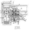
- the driving tool shown partially in section in FIGS. 1 to 5 has a housing 10 and a working cylinder 11 which receives a driving piston 12 to which a driving plunger 13 is connected. At the lower end of the working cylinder 11, a brake ring 14 is arranged.
- the working cylinder 11 is surrounded by a piston return chamber 15 which is connected to the working cylinder 11 via first radial bores 16 and second radial bores 17, the bores 16 on the side of the return chamber 15 being closed by an O-ring 18 which forms a check valve .
- the housing 11 has a handle part 20, in which a reservoir 21 for compressed air is formed, which can be connected to a compressed air source (not shown), for example via a compressed air hose.
- a ventilation channel 22 is formed in the handle part 20.
- a valve plate 23 is attached to the underside of the grip part 20, which engages with a projection 24 in a corresponding recess in the housing 10.
- the valve plate 23 is screwed to the handle 20 by means of a screw 25 which is arranged countersunk in the valve plate 23.
- the valve plate 23 supports a release lever 26 which is pivotably mounted at 27.
- a bore 30 in the grip part 20 is connected to a channel 31, which leads to the working space 32 of the cylinder 11. Above, the working drawer 32 is closed by a cover plug 33.
- a control valve device 36 is received in the bore 30. It has a main valve spool 37 and an auxiliary valve spool 38.
- the main valve spool 37 is designed as a stepped piston with an end-side active surface 37a facing the reservoir 21 and an oppositely directed larger active surface facing a main control chamber 39.
- the piston section of the main valve spool 37 which has the active surface 37a has two axially spaced O-rings 41, 42, the O-ring 41 cooperating with an upper valve seat, as a result of which the connection between the channel 31 and the reservoir 21 is interrupted.
- the lower O-ring 42 interacts with a stepped bush 43 which is sealingly received by the bore 30.
- the bushing bore guides the piston section of the main valve spool 37 in a sliding and sealing manner.
- the channel 31 is connected to an annular space 45 surrounding the main valve spool 37, which is connected to an annular space 46 surrounding the bush 43 via radial bores in the bush 43, which is in constant communication with the Vent channel 22.
- the working displacement 32 is therefore under atmospheric pressure.
- the central bore of the main valve spool 37 slidably and sealingly receives the upper end of a control sleeve 48 which has a radial flange 49 which is seated in an enlarged section of the bore 30.
- the control sleeve 48 has a plurality of radial bores 50 which connect the bore of the control sleeve 48 to the main control chamber 39.
- the radial flange 49 bears against the bush 43 from below and is in turn held by the valve plate 23 from below.
- the bore of the control sleeve 48 receives the upper part of the two-part auxiliary valve spool 38. This consists of an upper smooth cylindrical section 51 with an active surface 52 which faces the reservoir 21 via the bore 47 of the main valve slide 37.
- the upper part of the auxiliary valve slide also has a smooth cylindrical section 53.
- the intermediate rod is triangular in cross section in the central region, as shown at 54.
- a passage is thereby formed between the sections 51 and 53 between the rod 54 and the bore wall of the control sleeve 48 Bore of the control sleeve 48 has in the region of the flange 49 an enlarged section 55 into which the smooth cylindrical section 53 can be inserted in a sealing manner.
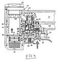
- the distance between the smooth cylindrical sections 51, 53 is such that either the upper smooth cylindrical section 51 sits sealingly in the bore of the control sleeve 48, while the section 53 releases the bore section 55, or the smooth cylindrical section 53 sits in the bore section 55, in which case the smooth cylindrical Section 51 projects upwards so far from the control sleeve 48 that the passage around the valve rod 54 is connected to the bore 47 of the main valve spool and thus to the reservoir 21 (FIG. 4).
- the lower part of the auxiliary valve spool 38 is arranged in a bore 56a of the valve plate 23. It has a valve piston section 56 which can be moved in a sealed manner in the bore 56a.
- a piston section 57 with a polygonal cross section - preferably triangular - is seated in a corresponding bore in the valve plate 23.
- the lower part of the auxiliary valve spool 38 has an active surface 57a and a polygonal active surface 66, which together via an oblique bore 58 in the valve plate 23 with the return chamber 15 communicates.
- a plunger 60 of a release valve 61 interacts with the release lever 26. It is pressed by the air pressure in the grip space 21 and in a bore 63a of an insert 63 supported by a spring 62 in the direction of the release lever 26. An O-ring 62a closes the bore in the valve plate 23 downwards.
- the plunger 60 which is triangular in cross-section in the lower region, has a further sealing ring 64 at the upper end, which sealingly cooperates with the bore 63a in the insert 63 when the plunger is lifted upwards using the release lever 26.
- a control chamber 65 is separated from the reservoir 21, which is connected to the bore 56a in the position of the auxiliary valve slide 38 shown in FIG. 1.
- the control valve device described operates as follows.
- Fig. 1 shows the unactuated state again.
- the trigger lever 26 is shown in its unactuated position.
- the pressure in the chamber 65 is the same as in the reservoir 21, since a connection is made via the bore 63a.
- the effective area 40 of the main valve slide 37 is larger than the effective area 37a facing the reservoir 21, the main valve slide is held in the closed position shown in FIG. 1, in which it blocks the connecting channel 31 from the compressed air and via the annular space 45 to the outlet channel 22 connects.
- the piston 12 is in its top dead center position.
- the main valve spool 37 is held in the closed position even when the upper part of the auxiliary valve spool 38 is in its upper position (which is shown approximately in FIG. 4).
- the cylindrical portion 51 is then outside the bore of the control sleeve 48, so that the passage between the connecting rod 54 and the control sleeve 48 is also connected via the bore 47 of the main valve spool 37 with compressed air, which then also via the radial bores 50 in the Main control chamber 39 can enter.
- valve tappet of the release valve 61 is raised and the sealing ring connected to the valve tappet 64 enters the lower section of the bore 63a of the insert 63, so that the compressed air is shut off.
- the sealing ring 62a emerges from the associated bore of the valve plate 23. Since the valve tappet is polygonal, preferably triangular in cross section in the lower region, a connection of the control chamber 65 to the atmosphere is established.
- the bores 56a, 55 and the radial bores 50 now also connect the main control chamber 39 to the atmosphere.
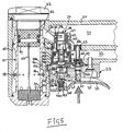
- the pressure acting on the smaller effective surface 37a of the main valve spool 37 therefore moves the main valve spool 37 into the opening position shown in FIG. 3, in which the O-rings 41, 42 interact with the bore of the bush-shaped insert 43 and thereby connect the connecting channel 31 to Shut off outlet duct 22.
- the compressed air enters the working stroke space 32 and drives the driving piston 12 downward so that a driving impact is carried out on a fastening means.
- the driving piston 12 hits the brake ring 14 with its lower end face. Its upper end face exposes the bores 16, and the compressed air can come out of the working space 32 via the bores 16 and the seal acting as a check valve Ring 18 flow into the return chamber 15.
- the return chamber 15 is connected to the bore 56a via the bores 58 and 58a. If this bore is closed (the throttling of bore 58 will be described further below), the control valve device described operates as a single-shot device. As long as the trigger lever 26 is actuated, the driving piston 12 remains in the bottom dead center position. When the release lever 26 is released, the valve pin 60 is pushed down again by the compression spring 62 and the air pressure.
- auxiliary control chamber 65 This separates the auxiliary control chamber 65 from the atmosphere.
- the auxiliary control chamber 65 is pressure-connected to the reservoir 21, so that a pressure can build up again in the main control chamber 39, which adjusts the main valve slide 37 back to the closed position.
- the working stroke space 32 is reconnected to the atmosphere, and the compressed air stored in the return space 15 drives the driving piston 12 back to the top dead center position. A state as shown in FIG. 1 is thereby obtained again.
- the control valve device described operates as an automatic valve. If the compressed air from the return chamber 15 passes through the bore 58 and 58a into the bore 56a, it acts on the lower active surface 57a and on the polygonal lower active surface 66 of the lower part of the auxiliary valve spool 38 and presses it upwards, while at the same time pressing the upper one Takes part and reached the position shown in Fig. 4.
- the plate 23 has a connection bore 102 below the bore 56a, in which the second part of the auxiliary valve spool is arranged, which normally goes into the atmosphere.
- a threaded bore of the release lever 26 sits a screw or threaded sleeve 100, the bore of which receives a cylindrical sealing element 101 made of elastomeric material, which is provided with a conical tip 105 at the upper end.
- the bore 102 remains free. As shown in Fig.
- the trigger lever 26 is raised so that the trigger valve 61 responds by the Sealing ring 64 dips into the corresponding bore 63a, but not so far that the conical tip 105 cooperates sealingly with the bore 102, the driving-in device described above is triggered, but only in single-shot operation, even if the throttle 59 in the connecting channel between the return chamber 15 and the second active surface 57a is open.
- the connection of the second active surface 57a to the atmosphere has the effect that the auxiliary valve slide cannot initiate automatic reversal of the main valve as long as the bore 102 is connected to the atmosphere.
- the operating mode depends on the actuation position of the release lever 26.
- sealing element other than the one shown can also effect a bore 102 seal, for example an annular seal.
- Fig. 6 shows a section through the housing 10 and part of the valve plate 23 in the region of a seal 70, via which the extension 24 is sealed off from the housing 10.
- the bore 58a can be seen, which connects the return chamber 15 to the bore 56a via the bore 58.
- the throttle 59 can be seen, which cooperates with the bore 58. It consists of a screw which has a knurled head 71, a threaded section 72 and a throttle section 73, which is conical at 74 at the end. With the help of the throttle screw, the size of the flow cross-section through the bore 58 can be set as desired. It determines the repetition frequency of the control valve device.
- the control valve device shown has the following advantages. It works without dynamically loaded springs. The only spring provided is the compression spring 62 for the trigger valve. However, it is not dynamically loaded. Furthermore, the control valve device shown is provided with very little dynamically loaded O-rings. In the embodiment shown, only five O-rings dynamically loaded with the stroke frequency are required, a number that is far exceeded by known control valve devices. For example, the upper part of the auxiliary valve spool 38 works completely without O-rings and the lower part has only one O-ring.
- the control valve device described can be used equally for single-shot and repeating operation.
- single-shot operation the lower part of the auxiliary valve slide remains in its lower position shown in FIG. 1.
- the control valve device shown provides an adaptation to the movement of the driving piston 12.
- the main valve spool is not switched to the closed position until the driving piston 12 has actually reached the bottom.
- the entire available driving energy can be used.
- the working stroke space 32 is only pressurized from the reservoir 21 when the driving piston 12 has actually reached its top dead center position.
- the piston sections 56 and 57 of the lower part have a particularly large active surface 57a and 66. It is therefore sufficient to hold the auxiliary valve slide 38 in the upper position, so that a reversal only takes place when the driving piston 12 has actually assumed its top dead center position.
- control valve device described can be installed in conventional nailers which are already in operation. Only the hole 58a has to be made additionally.
Landscapes
- Physics & Mathematics (AREA)
- Fluid Mechanics (AREA)
- Engineering & Computer Science (AREA)
- Mechanical Engineering (AREA)
- Portable Nailing Machines And Staplers (AREA)
- Automatic Assembly (AREA)
- Fluid-Driven Valves (AREA)
Applications Claiming Priority (2)
| Application Number | Priority Date | Filing Date | Title |
|---|---|---|---|
| DE8801114U | 1988-01-30 | ||
| DE8801114U DE8801114U1 (de) | 1988-01-30 | 1988-01-30 | Steuerventileinrichtung an einem mit Druckluft betriebenen Gerät zum Eintreiben von Befestigungsmitteln |
Publications (3)
| Publication Number | Publication Date |
|---|---|
| EP0326639A2 true EP0326639A2 (fr) | 1989-08-09 |
| EP0326639A3 EP0326639A3 (en) | 1990-02-28 |
| EP0326639B1 EP0326639B1 (fr) | 1992-07-01 |
Family
ID=6820119
Family Applications (1)
| Application Number | Title | Priority Date | Filing Date |
|---|---|---|---|
| EP88110554A Expired - Lifetime EP0326639B1 (fr) | 1988-01-30 | 1988-07-01 | Commande de soupape pour outil d'enfoncement pneumatique |
Country Status (4)
| Country | Link |
|---|---|
| US (1) | US4915013A (fr) |
| EP (1) | EP0326639B1 (fr) |
| JP (1) | JPH01210227A (fr) |
| DE (2) | DE8801114U1 (fr) |
Cited By (4)
| Publication number | Priority date | Publication date | Assignee | Title |
|---|---|---|---|---|
| EP0600206A1 (fr) * | 1992-12-02 | 1994-06-08 | Joh. Friedrich Behrens AG | Joint d'étanchéité pour le dispositif d'entraînement dans un outil pneumatique pour la mise en place de moyens de fixation |
| EP0600202A1 (fr) * | 1992-12-02 | 1994-06-08 | Joh. Friedrich Behrens AG | Dispositif de commande de valve |
| EP0774327A1 (fr) * | 1995-11-16 | 1997-05-21 | Stanley-Bostitch, Inc. | Outil d'enfoncement d'éléments de fixation avec un ensemble de soupape de contrÔle amélioré et ajustement de sensitivité de détente |
| EP0778109A1 (fr) * | 1995-12-07 | 1997-06-11 | Stanley-Bostitch, Inc. | Dispositif d'enfoncement d'éléments de fixation avec un clapet principal et un deuxième élément de clapet |
Families Citing this family (27)
| Publication number | Priority date | Publication date | Assignee | Title |
|---|---|---|---|---|
| US5174485A (en) * | 1989-12-19 | 1992-12-29 | Duo-Fast Corporation | Fastener driving tool |
| US5575051A (en) * | 1993-06-10 | 1996-11-19 | Marson/Creative Fastener Group | High impact power tool having shock absorbing means |
| US5604532A (en) * | 1994-06-06 | 1997-02-18 | Tillmanns; Josef | Apparatus and method for insitu inspection of pressurized vessels |
| WO1996012591A1 (fr) * | 1994-10-21 | 1996-05-02 | Senco Products, Inc. | Outil pneumatique de pose de fixations et sa commande electronique |
| US5522532A (en) * | 1995-03-14 | 1996-06-04 | Testo Industry Corp. | Single-shooting/continuous-shooting control switch for penumatic nail guns |
| IT1281548B1 (it) * | 1995-04-19 | 1998-02-18 | Fasco Spa | Meccanismo di scatto con dispositivo di sicurezza per fissatrice ad aria compressa |
| DE29508658U1 (de) * | 1995-05-24 | 1995-07-27 | Joh. Friedrich Behrens AG, 22926 Ahrensburg | Eintreibgerät für Befestigungsmittel |
| IT1279670B1 (it) * | 1995-11-02 | 1997-12-16 | Fasco Spa | Fissatrice ad aria compressa a valvola in testa funzionante a colpo singolo e a ripetizione. |
| US5896933A (en) * | 1995-11-16 | 1999-04-27 | Stanley Fastening Systems, L.P. | Fastener driving device having interchangeable control modules |
| US5628444A (en) * | 1995-11-16 | 1997-05-13 | Stanley-Bostitch, Inc. | Fastener driving device with main valve/frame valve arrangement |
| US5669542A (en) * | 1996-05-17 | 1997-09-23 | Stanley-Bostitch, Inc. | Fastener driving device having full cycle valve |
| EP0942808B1 (fr) * | 1996-12-06 | 2000-10-18 | Stanley Fastening Systems L.P. | Dispositif d'entrainement de fixation avec ensemble d'actionnement ameliore |
| US5806748A (en) * | 1997-12-03 | 1998-09-15 | Lee; Yun-Chung | Ejection switch for nailer |
| US6763990B2 (en) * | 2002-07-30 | 2004-07-20 | Yun-Chung Lee | Rotary cover head of nail gun |
| ITBO20030740A1 (it) * | 2003-12-10 | 2005-06-11 | Fasco Spa | Macchina fissatrice pneumatica |
| CN1293995C (zh) * | 2005-05-19 | 2007-01-10 | 力肯实业股份有限公司 | 打钉枪的扳机阀 |
| JP2007237328A (ja) * | 2006-03-08 | 2007-09-20 | Hitachi Koki Co Ltd | 燃焼式動力工具 |
| DE202007006646U1 (de) * | 2006-05-09 | 2007-08-09 | SAMSON POWER TOOL CO., LTD., Ta Li City | Schaltmechanismus für Auslöser von Druckluftwerkzeugen |
| US7784560B2 (en) | 2008-03-31 | 2010-08-31 | Illinois Tool Works Inc. | Cap assembly of a fastener-driving tool having switch mechanism incorporated therein for switching modes of operation of the fastener-driving tool |
| TWI404603B (zh) * | 2009-04-03 | 2013-08-11 | Basso Ind Corp | 具擊發保險裝置之打釘槍 |
| EP2434970B1 (fr) | 2009-05-26 | 2016-11-30 | Zimmer, Inc. | Outil à main destiné à enfoncer un clou à os dans un os fracturé |
| US9987067B2 (en) | 2012-07-11 | 2018-06-05 | Zimmer, Inc. | Bone fixation tool |
| EP3125797B1 (fr) | 2014-04-03 | 2019-05-22 | Zimmer, Inc. | Outil orthopedic pour la fixation d'un os |
| JP6819045B2 (ja) * | 2016-01-26 | 2021-01-27 | 工機ホールディングス株式会社 | 打込機 |
| TWI696527B (zh) * | 2016-03-18 | 2020-06-21 | 鑽全實業股份有限公司 | 氣動工具的安全性擊發控制裝置 |
| US10966704B2 (en) | 2016-11-09 | 2021-04-06 | Biomet Sports Medicine, Llc | Methods and systems for stitching soft tissue to bone |
| PL3446833T3 (pl) * | 2017-08-23 | 2020-10-19 | Joh. Friedrich Behrens Ag | Gwoździarka pneumatyczna z układem zaworu bezpieczeństwa |
Family Cites Families (18)
| Publication number | Priority date | Publication date | Assignee | Title |
|---|---|---|---|---|
| US3278103A (en) * | 1965-04-06 | 1966-10-11 | Senco Products | Fastener applying device |
| DE1603710A1 (de) * | 1966-03-11 | 1970-09-17 | Behrens Friedrich Joh | Druckluftbetaetigtes Eintreibgeraet zum Einschlagen von Befestigungsmitteln |
| US3477629A (en) * | 1966-11-23 | 1969-11-11 | Senco Products | Pneumatic fastener applying device |
| GB1199060A (en) * | 1966-12-19 | 1970-07-15 | Fastener Corp | Fastener Driving Tool |
| DE1603839C3 (de) * | 1967-07-13 | 1974-01-17 | Dieter Haubold Industrielle Nagelgeraete, 3005 Hemmingen-Westerfeld | Steuerventileinrichtung für einen Druckluftnagler |
| GB1226837A (fr) * | 1967-07-13 | 1971-03-31 | ||
| US3547003A (en) * | 1968-06-17 | 1970-12-15 | Fastener Corp | Fastener driving tool |
| US3583496A (en) * | 1969-02-19 | 1971-06-08 | Behrens Friedrich Joh | Compressed air-operated drive-in apparatus to drive-in fastening means such as nails, staples or the like |
| DE2104949A1 (de) * | 1970-02-11 | 1971-08-26 | Scala Raincomatic S.r.l., Bologna (Italien) | Automatische mit Druckluft beaufschlagte Einschlagpistole für das Einschlagen von Bolzen, Nägeln, Heftklammern u.dgl. mit wahlweiser Einstellung der Ausstoßhäufigkeit |
| US3771710A (en) * | 1971-09-27 | 1973-11-13 | Spotnails | Pneumatically powered fastener-driving tool |
| US3808620A (en) * | 1972-04-17 | 1974-05-07 | Senco Products | Remote valve for pneumatic tool |
| US3888404A (en) * | 1973-09-13 | 1975-06-10 | Duo Fast Corp | Safety for fastener driving tool |
| DE2516157C3 (de) * | 1975-04-14 | 1979-07-26 | Fa. Joh. Friedrich Behrens Ag, 2070 Ahrensburg | Drucklufteintreibgerät mit einem aus dem Mundstück herausragenden, als Führungszapfen dienenden Eintreibstößel |
| US4304349B1 (en) * | 1979-10-09 | 1996-02-27 | Duo Fast Cord | Fastener driving tool |
| US4319705A (en) * | 1979-10-31 | 1982-03-16 | Duo-Fast Corporation | Fastener driving tool |
| US4344555A (en) * | 1980-02-19 | 1982-08-17 | Signode Corporation | Self-cycling pneumatic fastener applying tool |
| JPS57157584A (en) * | 1981-03-24 | 1982-09-29 | Nippon Telegr & Teleph Corp <Ntt> | Photocoupling circuit for semiconductor laser |
| US4436237A (en) * | 1981-11-16 | 1984-03-13 | Senco Products, Inc. | Automatic firing system for pneumatic tools |
-
1988
- 1988-01-30 DE DE8801114U patent/DE8801114U1/de not_active Expired
- 1988-07-01 EP EP88110554A patent/EP0326639B1/fr not_active Expired - Lifetime
- 1988-07-01 DE DE8888110554T patent/DE3872508D1/de not_active Expired - Fee Related
- 1988-07-11 US US07/217,613 patent/US4915013A/en not_active Expired - Fee Related
- 1988-08-18 JP JP63205638A patent/JPH01210227A/ja active Pending
Cited By (4)
| Publication number | Priority date | Publication date | Assignee | Title |
|---|---|---|---|---|
| EP0600206A1 (fr) * | 1992-12-02 | 1994-06-08 | Joh. Friedrich Behrens AG | Joint d'étanchéité pour le dispositif d'entraînement dans un outil pneumatique pour la mise en place de moyens de fixation |
| EP0600202A1 (fr) * | 1992-12-02 | 1994-06-08 | Joh. Friedrich Behrens AG | Dispositif de commande de valve |
| EP0774327A1 (fr) * | 1995-11-16 | 1997-05-21 | Stanley-Bostitch, Inc. | Outil d'enfoncement d'éléments de fixation avec un ensemble de soupape de contrÔle amélioré et ajustement de sensitivité de détente |
| EP0778109A1 (fr) * | 1995-12-07 | 1997-06-11 | Stanley-Bostitch, Inc. | Dispositif d'enfoncement d'éléments de fixation avec un clapet principal et un deuxième élément de clapet |
Also Published As
| Publication number | Publication date |
|---|---|
| DE3872508D1 (de) | 1992-08-06 |
| DE8801114U1 (de) | 1988-03-31 |
| JPH01210227A (ja) | 1989-08-23 |
| EP0326639B1 (fr) | 1992-07-01 |
| EP0326639A3 (en) | 1990-02-28 |
| US4915013A (en) | 1990-04-10 |
Similar Documents
| Publication | Publication Date | Title |
|---|---|---|
| EP0326639B1 (fr) | Commande de soupape pour outil d'enfoncement pneumatique | |
| DE3119956C2 (de) | Schallgedämpftes Eintreibgerät für Befestigungsmittel | |
| DE1703110C3 (de) | Druckluftwerkzeug, insbesondere Druckluftnagler | |
| DE3347605C2 (de) | Pneumatisches Werkzeug | |
| DE1868901U (de) | Federloses druckventil. | |
| EP0600202A1 (fr) | Dispositif de commande de valve | |
| DE3222949C2 (de) | Automatische Abschußvorrichtung für ein pneumatisch betriebenes Werkzeug | |
| EP0205633B1 (fr) | Assemblage de soupape | |
| DE69607564T2 (de) | Eintreibgerät für Befestigungsmittel mit Hauptventil/Gehäuse-Ventilanordnung | |
| DE2604287C2 (de) | Druckluftnagler | |
| DE4022159C2 (de) | Vorrichtung zum Erzeugen eines Stufenfluiddruckes | |
| EP1130272B1 (fr) | Distributeur | |
| DE2607263A1 (de) | Druckluft-blindnietwerkzeug | |
| DE3131301A1 (de) | "vorrichtung zum verbinden mindestens zweier duennwandiger werkstuecke durch ein scher-quetsch-verfahren" | |
| DE102004046976B4 (de) | Mehrwegeventil | |
| DE2516157C3 (de) | Drucklufteintreibgerät mit einem aus dem Mundstück herausragenden, als Führungszapfen dienenden Eintreibstößel | |
| DE1603785A1 (de) | Pneumatische Eintreibvorrichtung fuer Naegel,Klammern od.dgl. | |
| DE2250475C3 (de) | Steuerventileinrichtung für den doppelt wirkenden Arbeitszylinder eines mit Druckluft betriebenen Schlaggeräts | |
| DE19804456C1 (de) | Auslösegesichertes Eintreibgerät für Befestigungsmittel | |
| DE3709557C1 (de) | Vorrichtung zur Bildung eines Kunststoff-Reaktionsgemisches | |
| DE1478882C (de) | Ventilanordnung zum selbsttätigen Steuern des Rückhubes für eine pneumatische Nagelvorrichtung | |
| AT241987B (de) | Druckmittelsteuerung für Pressen mit einer Kupplung und einer Bremse | |
| DE1908150C3 (de) | Steuerventileinrichtung an einem Druckluftnagler | |
| DE2035647C3 (de) | Steuereinrichtung an einem druckmittelbetätigten Nagler | |
| DE2103016C3 (de) | Druckluftschlagwerkzeug |
Legal Events
| Date | Code | Title | Description |
|---|---|---|---|
| PUAI | Public reference made under article 153(3) epc to a published international application that has entered the european phase |
Free format text: ORIGINAL CODE: 0009012 |
|
| AK | Designated contracting states |
Kind code of ref document: A2 Designated state(s): DE FR GB IT |
|
| PUAL | Search report despatched |
Free format text: ORIGINAL CODE: 0009013 |
|
| AK | Designated contracting states |
Kind code of ref document: A3 Designated state(s): DE FR GB IT |
|
| 17P | Request for examination filed |
Effective date: 19900305 |
|
| 17Q | First examination report despatched |
Effective date: 19910610 |
|
| GRAA | (expected) grant |
Free format text: ORIGINAL CODE: 0009210 |
|
| AK | Designated contracting states |
Kind code of ref document: B1 Designated state(s): DE FR GB IT |
|
| REF | Corresponds to: |
Ref document number: 3872508 Country of ref document: DE Date of ref document: 19920806 |
|
| ITF | It: translation for a ep patent filed | ||
| GBT | Gb: translation of ep patent filed (gb section 77(6)(a)/1977) | ||
| ET | Fr: translation filed | ||
| PLBE | No opposition filed within time limit |
Free format text: ORIGINAL CODE: 0009261 |
|
| STAA | Information on the status of an ep patent application or granted ep patent |
Free format text: STATUS: NO OPPOSITION FILED WITHIN TIME LIMIT |
|
| 26N | No opposition filed | ||
| PGFP | Annual fee paid to national office [announced via postgrant information from national office to epo] |
Ref country code: FR Payment date: 19950519 Year of fee payment: 8 |
|
| PGFP | Annual fee paid to national office [announced via postgrant information from national office to epo] |
Ref country code: GB Payment date: 19950620 Year of fee payment: 8 |
|
| PGFP | Annual fee paid to national office [announced via postgrant information from national office to epo] |
Ref country code: DE Payment date: 19950823 Year of fee payment: 8 |
|
| PG25 | Lapsed in a contracting state [announced via postgrant information from national office to epo] |
Ref country code: GB Effective date: 19960701 |
|
| GBPC | Gb: european patent ceased through non-payment of renewal fee |
Effective date: 19960701 |
|
| PG25 | Lapsed in a contracting state [announced via postgrant information from national office to epo] |
Ref country code: FR Effective date: 19970328 |
|
| PG25 | Lapsed in a contracting state [announced via postgrant information from national office to epo] |
Ref country code: DE Effective date: 19970402 |
|
| REG | Reference to a national code |
Ref country code: FR Ref legal event code: ST |
|
| PG25 | Lapsed in a contracting state [announced via postgrant information from national office to epo] |
Ref country code: IT Free format text: LAPSE BECAUSE OF NON-PAYMENT OF DUE FEES;WARNING: LAPSES OF ITALIAN PATENTS WITH EFFECTIVE DATE BEFORE 2007 MAY HAVE OCCURRED AT ANY TIME BEFORE 2007. THE CORRECT EFFECTIVE DATE MAY BE DIFFERENT FROM THE ONE RECORDED. Effective date: 20050701 |