EP0326738A2 - Dochte - Google Patents
Dochte Download PDFInfo
- Publication number
- EP0326738A2 EP0326738A2 EP88307922A EP88307922A EP0326738A2 EP 0326738 A2 EP0326738 A2 EP 0326738A2 EP 88307922 A EP88307922 A EP 88307922A EP 88307922 A EP88307922 A EP 88307922A EP 0326738 A2 EP0326738 A2 EP 0326738A2
- Authority
- EP
- European Patent Office
- Prior art keywords
- wick
- strip
- tube
- fixtures
- junction
- Prior art date
- Legal status (The legal status is an assumption and is not a legal conclusion. Google has not performed a legal analysis and makes no representation as to the accuracy of the status listed.)
- Withdrawn
Links
Images



Classifications
-
- F—MECHANICAL ENGINEERING; LIGHTING; HEATING; WEAPONS; BLASTING
- F23—COMBUSTION APPARATUS; COMBUSTION PROCESSES
- F23D—BURNERS
- F23D3/00—Burners using capillary action
- F23D3/02—Wick burners
- F23D3/08—Wick burners characterised by shape, construction, or material, of wick
Definitions
- the present invention relates to a hollow tubular burning wick produced by forming into a tube a strip of wick material consisting of a burner part and an fuel suction part by abutting and joining to each other the ends of the strip.
- wicks for lamps or the like Some comprise a burner part and an oil suction part and others also include a stretching part.
- a wick body having a burner part and an oil suction part is knitted into a continuous strip on a wrap knitting machine (raschel machine).
- the wick is then cut to a predetermined length by an appropriate cutter.
- the wick body is formed by looping the strip to form a hollow tube by abutting the opposite cut end edges, and thereafter, the abutted end edges are stitched together by zigzag stitching along the join which extends axially of the wick.
- Such a type of burning wick is disclosed, for example, in Japanese Utility Model laid open No. 52-157535 (No. 157535/1977), Japanese Patent laid open No. 51-17038 (No. 17038/1966) and No. 51-44325 (No. 44325/1976).
- the required stitching work complicates the manufacturing process and increases the cost.
- Japanese Patent laid open No. 61-246505 (No. 246505/1986) corresponding to U.S. Patent No. 4652235 and No. 62-66008 (No. 66008/1987) discloses a method of obtaining a hollow tube burning wick without requiring any stitching work of the opposite abutting edges, as mentioned above.
- the present invention provides a tubular wick comprising a strip of wick material including a burner part and a fuel suction part, the ends of the strip being abutted and joined to form the tube, characterised by a plurality of discrete staple- or channel-like connecting fixtures inserted from the outside of the tube through the wick material straddling the junction of the abutting ends of the strip, the ends of the fixtures on the inside of the tube being bent back towards the wick material to grip the wick material; and a holding tape which is disposed along the junction over said connecting fixtures and extends part-way along the wick material on both sides of the junction and over parts of the burner part and said fuel suction part.
- the invention also provides a method of forming a tubular wick comprising a strip of wick material including a burner part and a fuel suction part, including the steps of forming the strip of material into a tube by abutting and joining the ends of the strip, characterised by the steps of inserting a plurality of discrete staple- or channel-like connecting fixtures from the outside of the tube through the wick material straddling and spaced along the junction of the abutting ends of the strip, and bending back the ends of the fixtures on the inside of the tube towards the wick material to grip the wick material; and applying a holding tape along the junction over the connecting fixtures and extending part-way along the wick material on both sides of the junction and over parts of the burner part and fuel suction part.
- connecting fixtures which may be anticorrosion treated and which are arranged to straddle the opposite abutting edges of the wick material, and by a holding tape which is applied on the connecting fixtures so as to straddle on the opposite abutting edges of the wick body and on a burner part and an oil suction part in an axial direction of the wick body, whereby a very low manufacturing and material cost is obtained.
- the wick 1 comprises a burner part 2 and an oil suction part 3.
- the burner part 2 is made of heat resistant fibre yarn, such as glass fibre or the like.
- the oil suction part consists of oil soakable fibre yarn, such as cotton, staple fibre or the like.
- the burner part 2 and the oil suction part 3 are knitted simultaneously on a wrap knitting machine (raschel machine) in a well known manner.
- a wrap knitting machine raschel machine
- return ends of the yarns 2 b and 3 a intermix one into another to be crossed in a comb like shape.
- This cross connecting portion 4 is integrally combined by a binding yarn 5.
- the knitting of the wick body in such a shape is done automatically knitted on a wrap knitting machine of the type mentioned above.
- the wick body thus obtained is then cut laterally to a predetermined required length and is looped to form a hollow tube by abutting the respective end edge portions of the burner part 2 and the oil suction part 3.
- An outer applying tape 7 is then wound entirely around the wick to straddle the opposite abutting edges 6 and overlie the cross connecting portion 4 of the burner part 2 and the oil suction part 3.
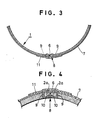
- a plurality of channel-like or staple-like connecting fixtures 8 which are formed independently from each other, are inserted across the abutting edge portions spaced along the join.
- the connecting fixtures 8 are treated by a conventional anticorrosion treatment using for example an anticorrosion pigment, such as zinc chromate, lead cyanamide or the like.
- the connecting fixture 8 has a leg portion 9 at each end which passes through the wick respectively on opposite sides of the join.
- the leading edges of the leg portions 9 are further returned from the inside of the wick body toward the outside direction thereby firmly embracing respective yarns 2a by means of leading engaging edges 10 (see Figure 4).
- leading engaging edges 10 see Figure 4
- the same structure also exists in the oil suction part 3.
- the connecting fixtures 8 are respectively constituted independently from each other, the distance between them and their position can be selected according to the desired joining strength.
- the connecting fixtures 8 are arranged along the opposite abutting edges 6, it is easy to automate the process using an automatic machine because the joining line is straight.
- an oval shaped holding tape 11 is applied to the outside of the wick over the connecting fixtures 8 and along the axial direction of the abutting edge 6 and extends over parts of the burner part 2 and the oil suction portion 3.
- the holding tape 11 may be, for example, synthetic resins, papers on which a reinforcing treatment has been performed, or other similar materials.
- the width of the holding tape 11 may be such that it does not extend far around the wick beyond the join because the opposite abutting edges 6 of the join are firmly combined by the connecting fixtures 8 and further are joined more closely to the connecting fixtures 8 by the holding tape 11. Accordingly, the opposite edges 6 are joined and held integrally by triple connecting means of the outer applying tape 7, the connecting fixtures 8 and the holding tape 11. Therefore, the strength is high in vertical, horizontal and slant directions of the opposite abutting edges and the formation of gaps between the edges is prevented.
- the connecting fixtures are constituted independently from each other and their number and position may be freely selected in accordance with the joining strength of the opposite abutting edges, it is very economical. For example, if a strong joining strength is required, as for a large sized wick, the number of connecting fixtures can be increased and they may be arranged closely at the opposite abutting edges of the burner part and the oil suction part. Further, because the anticorrosion treatment is performed on the connecting fixtures, they will not be corroded by the fuel and so the very firm connection lasts for a long time.
- the connecting fixture itself is very simple in its shape and structure and the holding tape has the size covering only relatively closely around the opposite abutting edges of the wick body, a reinforced joining tape having a large area joining element having a zigzag or checkers shape is not required. Therefore, with the present invention, the fully satisfactory effect in the material field is obtained and the joining strength is strong despite the simple joining structure, and so the wick has the necessary mechanical strength required when the wick is raised and lowered in use.
Landscapes
- Engineering & Computer Science (AREA)
- Chemical & Material Sciences (AREA)
- Combustion & Propulsion (AREA)
- Mechanical Engineering (AREA)
- General Engineering & Computer Science (AREA)
- Lighters Containing Fuel (AREA)
- Connection Of Plates (AREA)
- Knitting Of Fabric (AREA)
- Clamps And Clips (AREA)
- Professional, Industrial, Or Sporting Protective Garments (AREA)
Applications Claiming Priority (2)
| Application Number | Priority Date | Filing Date | Title |
|---|---|---|---|
| JP12370/88 | 1988-02-01 | ||
| JP1988012370U JPH01117415U (de) | 1988-02-01 | 1988-02-01 |
Publications (2)
| Publication Number | Publication Date |
|---|---|
| EP0326738A2 true EP0326738A2 (de) | 1989-08-09 |
| EP0326738A3 EP0326738A3 (de) | 1990-05-02 |
Family
ID=11803380
Family Applications (1)
| Application Number | Title | Priority Date | Filing Date |
|---|---|---|---|
| EP88307922A Withdrawn EP0326738A3 (de) | 1988-02-01 | 1988-08-26 | Dochte |
Country Status (5)
| Country | Link |
|---|---|
| US (1) | US4836773A (de) |
| EP (1) | EP0326738A3 (de) |
| JP (1) | JPH01117415U (de) |
| KR (1) | KR890013414A (de) |
| CN (1) | CN1040671A (de) |
Families Citing this family (3)
| Publication number | Priority date | Publication date | Assignee | Title |
|---|---|---|---|---|
| JP3285502B2 (ja) * | 1996-10-30 | 2002-05-27 | 株式会社東海 | 液体燃料用燃焼器具 |
| WO2006061904A1 (ja) * | 2004-12-09 | 2006-06-15 | Toyotomi Co., Ltd. | 液体燃料燃焼器具用芯 |
| KR100698773B1 (ko) * | 2005-03-02 | 2007-03-23 | 손현자 | 역류방지용 배수트랩 |
Family Cites Families (10)
| Publication number | Priority date | Publication date | Assignee | Title |
|---|---|---|---|---|
| BE425015A (de) * | ||||
| US1367392A (en) * | 1919-05-26 | 1921-02-01 | Sears Roebuck & Co | Lighting-ring |
| US2493961A (en) * | 1948-01-22 | 1950-01-10 | Metal Textile Corp | Wick for oil burners |
| GB693123A (en) * | 1950-11-14 | 1953-06-24 | Alexander White Hick | Improved wick for kerosene and like burners |
| GB708412A (en) * | 1951-08-02 | 1954-05-05 | Alexander White Hick | Improved wick for kerosene and like burners |
| DE1188874B (de) * | 1963-02-07 | 1965-03-11 | E H Hans Ziller Dr Ing | Verfahren zum Verbinden von Rissen in Stahlseilfoerdergurten |
| JPS572905A (en) * | 1980-06-09 | 1982-01-08 | Matsushita Electric Ind Co Ltd | Wick for kerosene burner |
| JPS5912211A (ja) * | 1983-05-12 | 1984-01-21 | Silver Kogyo Kk | 燃焼器具用芯 |
| JPH0646086B2 (ja) * | 1985-04-22 | 1994-06-15 | 有限会社喜立産業 | 無縫製石油燃焼芯 |
| JPS6266008A (ja) * | 1985-09-17 | 1987-03-25 | Kiritsu Sangyo:Kk | 無縫製燃焼芯 |
-
1988
- 1988-02-01 JP JP1988012370U patent/JPH01117415U/ja active Pending
- 1988-08-22 KR KR1019880010657A patent/KR890013414A/ko not_active Ceased
- 1988-08-26 EP EP88307922A patent/EP0326738A3/de not_active Withdrawn
- 1988-08-30 US US07/238,278 patent/US4836773A/en not_active Expired - Fee Related
- 1988-08-31 CN CN88106461A patent/CN1040671A/zh active Pending
Also Published As
| Publication number | Publication date |
|---|---|
| CN1040671A (zh) | 1990-03-21 |
| US4836773A (en) | 1989-06-06 |
| JPH01117415U (de) | 1989-08-08 |
| EP0326738A3 (de) | 1990-05-02 |
| KR890013414A (ko) | 1989-09-23 |
Similar Documents
| Publication | Publication Date | Title |
|---|---|---|
| DE69714419T2 (de) | Verbesserung an jalousien | |
| DE3513909A1 (de) | Elektrischer heizkoerper und verfahren zu seiner herstellung | |
| NZ192168A (en) | Producing endless fabric | |
| US4501133A (en) | Dual needle arrangement | |
| EP1085120A1 (de) | Band für den Umlauf in Maschinen sowie Verfahren zu dessen Herstellung | |
| DE2855603A1 (de) | Umwicklungseinrichtung | |
| EP0326738A2 (de) | Dochte | |
| KR19990028274A (ko) | 병합된 클립 조립체 | |
| DE2930642C2 (de) | Gewebtes Reißverschlußband | |
| US4720260A (en) | Burning wick for oil burning apparatus | |
| DE2554408B2 (de) | Kettengewirkte Verstärkungseinlage | |
| KR900005058B1 (ko) | 오일연소장치용 관형심지 | |
| NO855121L (no) | Spiral-leddbaand med redusert luftgjennomtrengelighet. | |
| JPS5913446Y2 (ja) | 燃焼器具用芯 | |
| JPS6274815A (ja) | ピントルワイヤのまわりに巻き付けられた充填ヘリツクスを有するスパイラルリンクベルト | |
| DE2944453C2 (de) | Kragen für Bekleidungsstücke und Verfahren zu seiner Herstellung | |
| JPH0220577Y2 (de) | ||
| JPS5913447Y2 (ja) | 燃焼器具用芯 | |
| JPS6341882Y2 (de) | ||
| JPH018806Y2 (de) | ||
| KR960008706Y1 (ko) | 끈 결속 바늘 | |
| JPS629360Y2 (de) | ||
| DE29808348U1 (de) | Textilband für Transportzwecke | |
| JPS6329760Y2 (de) | ||
| JPS63214315A (ja) | 排水用濾材とその製造方法 |
Legal Events
| Date | Code | Title | Description |
|---|---|---|---|
| PUAI | Public reference made under article 153(3) epc to a published international application that has entered the european phase |
Free format text: ORIGINAL CODE: 0009012 |
|
| AK | Designated contracting states |
Kind code of ref document: A2 Designated state(s): BE DE ES FR GB IT NL |
|
| PUAL | Search report despatched |
Free format text: ORIGINAL CODE: 0009013 |
|
| AK | Designated contracting states |
Kind code of ref document: A3 Designated state(s): BE DE ES FR GB IT NL |
|
| 17P | Request for examination filed |
Effective date: 19900703 |
|
| 17Q | First examination report despatched |
Effective date: 19910821 |
|
| STAA | Information on the status of an ep patent application or granted ep patent |
Free format text: STATUS: THE APPLICATION IS DEEMED TO BE WITHDRAWN |
|
| 18D | Application deemed to be withdrawn |
Effective date: 19920103 |