EP0326741A2 - Capteur à élément magnétorésistif unique non polarisé pour tête de lecture multiple - Google Patents
Capteur à élément magnétorésistif unique non polarisé pour tête de lecture multiple Download PDFInfo
- Publication number
- EP0326741A2 EP0326741A2 EP88309855A EP88309855A EP0326741A2 EP 0326741 A2 EP0326741 A2 EP 0326741A2 EP 88309855 A EP88309855 A EP 88309855A EP 88309855 A EP88309855 A EP 88309855A EP 0326741 A2 EP0326741 A2 EP 0326741A2
- Authority
- EP
- European Patent Office
- Prior art keywords
- sense
- sensor
- regions
- magneto
- contacts
- Prior art date
- Legal status (The legal status is an assumption and is not a legal conclusion. Google has not performed a legal analysis and makes no representation as to the accuracy of the status listed.)
- Withdrawn
Links
Images

Classifications
-
- G—PHYSICS
- G11—INFORMATION STORAGE
- G11B—INFORMATION STORAGE BASED ON RELATIVE MOVEMENT BETWEEN RECORD CARRIER AND TRANSDUCER
- G11B5/00—Recording by magnetisation or demagnetisation of a record carrier; Reproducing by magnetic means; Record carriers therefor
- G11B5/127—Structure or manufacture of heads, e.g. inductive
- G11B5/33—Structure or manufacture of flux-sensitive heads, i.e. for reproduction only; Combination of such heads with means for recording or erasing only
- G11B5/39—Structure or manufacture of flux-sensitive heads, i.e. for reproduction only; Combination of such heads with means for recording or erasing only using magneto-resistive devices or effects
- G11B5/3903—Structure or manufacture of flux-sensitive heads, i.e. for reproduction only; Combination of such heads with means for recording or erasing only using magneto-resistive devices or effects using magnetic thin film layers or their effects, the films being part of integrated structures
- G11B5/3906—Details related to the use of magnetic thin film layers or to their effects
- G11B5/3945—Heads comprising more than one sensitive element
- G11B5/3948—Heads comprising more than one sensitive element the sensitive elements being active read-out elements
- G11B5/3958—Heads comprising more than one sensitive element the sensitive elements being active read-out elements the active elements being arranged in a single plane, e.g. "matrix" disposition
- G11B5/3961—Heads comprising more than one sensitive element the sensitive elements being active read-out elements the active elements being arranged in a single plane, e.g. "matrix" disposition disposed at an angle to the direction of the track or relative movement
-
- G—PHYSICS
- G01—MEASURING; TESTING
- G01R—MEASURING ELECTRIC VARIABLES; MEASURING MAGNETIC VARIABLES
- G01R33/00—Arrangements or instruments for measuring magnetic variables
- G01R33/02—Measuring direction or magnitude of magnetic fields or magnetic flux
- G01R33/06—Measuring direction or magnitude of magnetic fields or magnetic flux using galvano-magnetic devices
- G01R33/09—Magnetoresistive devices
-
- G—PHYSICS
- G11—INFORMATION STORAGE
- G11B—INFORMATION STORAGE BASED ON RELATIVE MOVEMENT BETWEEN RECORD CARRIER AND TRANSDUCER
- G11B5/00—Recording by magnetisation or demagnetisation of a record carrier; Reproducing by magnetic means; Record carriers therefor
- G11B5/02—Recording, reproducing, or erasing methods; Read, write or erase circuits therefor
- G11B5/09—Digital recording
-
- G—PHYSICS
- G11—INFORMATION STORAGE
- G11B—INFORMATION STORAGE BASED ON RELATIVE MOVEMENT BETWEEN RECORD CARRIER AND TRANSDUCER
- G11B5/00—Recording by magnetisation or demagnetisation of a record carrier; Reproducing by magnetic means; Record carriers therefor
- G11B5/127—Structure or manufacture of heads, e.g. inductive
- G11B5/33—Structure or manufacture of flux-sensitive heads, i.e. for reproduction only; Combination of such heads with means for recording or erasing only
- G11B5/39—Structure or manufacture of flux-sensitive heads, i.e. for reproduction only; Combination of such heads with means for recording or erasing only using magneto-resistive devices or effects
- G11B5/3903—Structure or manufacture of flux-sensitive heads, i.e. for reproduction only; Combination of such heads with means for recording or erasing only using magneto-resistive devices or effects using magnetic thin film layers or their effects, the films being part of integrated structures
- G11B5/398—Specially shaped layers
-
- H—ELECTRICITY
- H10—SEMICONDUCTOR DEVICES; ELECTRIC SOLID-STATE DEVICES NOT OTHERWISE PROVIDED FOR
- H10N—ELECTRIC SOLID-STATE DEVICES NOT OTHERWISE PROVIDED FOR
- H10N50/00—Galvanomagnetic devices
- H10N50/10—Magnetoresistive devices
Definitions
- This invention relates to unbiased single magneto-resistive element ganged read head sensors.
- an unbiased single magneto-resistive element ganged read head sensor characterised by comprising: a elongate magneto-resistive sensor element; a plurality of sense current contacts contacting the sensor element and defining a plurality of sense regions between the contacts; the regions of the sensor element in the area of the contacts being maintained with substantially the same coercivity as that of the sense regions; and no transverse biasing means.
- the sensor element has a lower edge
- the easy axis of magnetisation to said sensor element is parallel with said lower edge
- the contacts have parallel facing sides each of which is perpendicular to the lower edge
- apparatus comprising: an unbiased ganged, magneto-resistive sensor characterised by comprising: a plurality of sense regions formed from a single magneto-resistive element having a magnetisation vector M aligned parallel to the easy axis in the absence of external fields; means for providing a sense current in each of the sense regions, each sense current having a vector I substantially parallel with said easy axis magnetisation vector M; a magnetic recording medium mounted adjacent to said sensor such that relative motion between them can occur, the magnetic medium having a plurality of magnetisation transitions recorded thereon in a parallel track arrangement providing magnetic flux pulses to respective of said sense regions as the transitions of respective tracks pass the sensor, the peak flux amplitude of the pulses being sufficient to rotate a respective sense region's magnetisation vector M away from the sense current vector I so that the angle between them is in the range of 40° to 50°, whereby the sensor response in the region of the pulse peak is approximately a linear function of magnetic flux of the
- Figure 1 illustrates part of an unbiased single magneto-resistive element ganged read head sensor according to the present invention having an elongate magneto-resistive sensor element 10. Whilst the head sensor is shown with only two sensor regions 12,14 for sensing two data tracks 32,34 of a flat recording media 30, the concept of the present invention can be extended to any number of sense regions and tracks. Further, while the present invention is described in relation to data tracks having guard bands 36, the present invention is also useful for reading servo tracks (not shown) by proper electronic switching.
- the sensor element 10 is conventionally composed of 80:20 nickel-iron alloy.
- the sensor element 10 has an upper edge 13 and a lower edge 11, the edges being parallel to each other and, when mounted in a read head (the other elements of which are not shown in Figure 1 for the purpose of clarity), the edges are also parallel to the recording media 30.
- the head sensor In some devices, such as Winchester disk drives, the head sensor will fly a short distance above the recording media. In other devices, such as tape drives, the head sensor will be mechanically fixed in relation to the recording media.
- the easy axis of magnetisation of the sensor element 10 is directed parallel to these upper and lower edges 11,13, as indicated by a magnetic vector M.
- the sensor element 10 is divided into the two sense regions 12,14 by contacts 20,22,24 connected to the sensor element on one side thereof. In those portions of the contacts connected to the sensor element 10, the facing sides of the contacts are parallel to each other and perpendicular to the lower edge 11 of the sensor element.
- each sense region 12,14 between facing contacts 20,22 and 22,24 is nominally the width of one of the tracks 32,34 in which data has been magnetically pre-recorded.
- the tracks are conventionally separated by the guard bands 36.
- the width of contacts 20,22,24 is nominally that of the guard bands 36.
- the recording media 30 is in motion relative to the sensor element in the direction shown by vector V.
- Data recorded along the track in the form of magnetic flux transitions passes serially under a sense region and causes a localised change in resistivity which can be electronically sensed and converted into data.
- a current source is connected to the conductor 20 and a current drain is connected to the conductor 24. So connected, current I flows through the sensor element 10 in the direction indicated by vector I.
- a first voltage sensor 16 is connected between the contact 20 and the contact 22, and a second voltage sensor 18 is connected between the contact 22 and the contact 24.
- the voltage drop across the sense region 12 is sensed by the voltage sensor 16 and the voltage drop across the other sense region 14 is sensed by the voltage sensor 18. It will be appreciated that the voltage drop across the respective sense regions will change according to the magnetic fields in the sense regions originating from the recording media 30 (and tracks 32, 34 when the sensor element is properly aligned above them).
- the peak flux strength of a transistion from the recording media 30 should be sufficient to rotate the magnetisation vector M so that the response of the sensor to the peak flux is a linear replication of the flux. This occurs when the peak flux rotates the vector M approximately 40° to 50°.
- the provision of no external magnetic biasing fields permits the operation of magnetic relaxation of the sensor element. This inherently reduces the transmission of the effects of a localised magnetic perturbation through the sensor element. As a result cross talk from adjacent tracks is reduced. This permits tracks to be recorded far more closely together than would otherwise be expected.
- sufficient signal-to-noise ratio exists with conventional low noise thin film recording media recorded conventionally with data yielding a 300 gauss (0.03 T) peak magnetic field at the surface of the recording media with the sensor element spaced (i.e. flying or mechanically fixed) from the recording media 30 a distance of 0.05 - 0.25 ⁇ m such that the distance between the facing surfaces of the contacts 20,22,24 can be in the range of 2 to 4 ⁇ m and the width of the contacts 20,22,24 being in the range 1 to 2 ⁇ m, with the tracks 32,34 and guard bands being of corresponding dimensions, such that around 2400 tracks per centimetre (6000 tracks per inch) can be read.
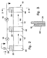
- Figure 2 illustrates a second embodiment of an unbiased single magneto-resitive element ganged read head sensor according to the present invention in which cross talk is even further reduced, thereby permitting even greater track density.
- This embodiment is essentially the same as that of Figure 1, with the addition of anti-ferro-magnetic material 40,42,44 exchange-coupled to the sensor element 10 in the region of the contacts 20,22,24, but on the opposite side of the sensor element 10 therefrom. Deposition of the anti-ferro-magnetic material on the opposite side of the contacts is not necessary if the anti-ferro-magnetic material is a conductor.
- the anti-ferro-magnetic material 40,42,44 which is convention strictlyally 50:50 iron-manganese, is exchange-coupled to cover substantially the same area of the sensor element as the corresponding contacts 20,22,24, but on the opposite side of the sensor element as shown in Figure 3.
- This exchange-coupled anti-ferro-magnetic material "freezes" the magnetic orientation of the magneto-resistive material of the sensor element to which it is coupled. This effectively prevents magnetic perturbation induced in one sense region 12,14 from being transmitted through the sensor element to the other sense region 14,12. Thus cross talk is reduced to only that caused by the direct influence of one track, e.g. the track 32, on the adjacent sense region, e.g. the sense region 14.
Landscapes
- Engineering & Computer Science (AREA)
- Manufacturing & Machinery (AREA)
- Physics & Mathematics (AREA)
- Mathematical Physics (AREA)
- Condensed Matter Physics & Semiconductors (AREA)
- General Physics & Mathematics (AREA)
- Magnetic Heads (AREA)
- Measuring Magnetic Variables (AREA)
Applications Claiming Priority (2)
| Application Number | Priority Date | Filing Date | Title |
|---|---|---|---|
| US07/152,783 US4851944A (en) | 1987-02-17 | 1988-02-05 | Ganged MR head sensor |
| US152783 | 1988-02-05 |
Publications (2)
| Publication Number | Publication Date |
|---|---|
| EP0326741A2 true EP0326741A2 (fr) | 1989-08-09 |
| EP0326741A3 EP0326741A3 (fr) | 1991-01-09 |
Family
ID=22544425
Family Applications (1)
| Application Number | Title | Priority Date | Filing Date |
|---|---|---|---|
| EP19880309855 Withdrawn EP0326741A3 (fr) | 1988-02-05 | 1988-10-20 | Capteur à élément magnétorésistif unique non polarisé pour tête de lecture multiple |
Country Status (3)
| Country | Link |
|---|---|
| US (1) | US4851944A (fr) |
| EP (1) | EP0326741A3 (fr) |
| JP (1) | JPH01208715A (fr) |
Cited By (4)
| Publication number | Priority date | Publication date | Assignee | Title |
|---|---|---|---|---|
| EP0381541A3 (fr) * | 1989-02-03 | 1991-02-06 | Sharp Kabushiki Kaisha | Dispositif magnétorésistif supraconducteur |
| EP0472162A1 (fr) * | 1990-08-21 | 1992-02-26 | Sony Corporation | Tête magnétique |
| EP0440386A3 (en) * | 1990-01-29 | 1993-04-14 | International Business Machines Corporation | Magnetic head and process for manufacturing same |
| EP0989547A3 (fr) * | 1998-07-31 | 2005-09-28 | Koninklijke Philips Electronics N.V. | Dispositif à tête magnétique à films minces |
Families Citing this family (11)
| Publication number | Priority date | Publication date | Assignee | Title |
|---|---|---|---|---|
| US5229894A (en) * | 1988-02-16 | 1993-07-20 | M.R. Sensors Limited | Method and apparatus for reading and decoding information using a magnetoresistive sensor |
| US5107385A (en) * | 1989-11-16 | 1992-04-21 | Applied Magnetics Corporation | Read head assembly for multiple-width tracks |
| DE69126082T2 (de) * | 1990-09-27 | 1997-10-02 | Toshiba Kawasaki Kk | Magnetischer Kopf |
| US5155643A (en) * | 1990-10-30 | 1992-10-13 | Mars Incorporated | Unshielded horizontal magnetoresistive head and method of fabricating same |
| US5323285A (en) * | 1992-06-23 | 1994-06-21 | Eastman Kodak Company | Shielded dual element magnetoresistive reproduce head exhibiting high density signal amplification |
| JPH077196A (ja) * | 1992-12-29 | 1995-01-10 | Eastman Kodak Co | 磁界センサ及び磁界検知方法 |
| US5825593A (en) * | 1994-02-18 | 1998-10-20 | Seagate Technology, Inc. | Electric field modulated MR sensor |
| US7405907B2 (en) * | 2004-08-03 | 2008-07-29 | O-Mass As | Adjacent magnetoresistive read head and method for obtaining position error signal |
| US20070019335A1 (en) * | 2005-07-20 | 2007-01-25 | Hitachi Global Storage Technologies, Inc. | Tape medium read head with unitary formation of multiple elements |
| US8243398B2 (en) * | 2008-06-18 | 2012-08-14 | Oracle America, Inc. | Hybrid trackwidth read element |
| US10002625B1 (en) * | 2017-02-14 | 2018-06-19 | Seagate Technology Llc | Recording head with multiple magnetic writers simultaneously writing to adjacent tracks |
Family Cites Families (6)
| Publication number | Priority date | Publication date | Assignee | Title |
|---|---|---|---|---|
| US3967368A (en) * | 1972-10-11 | 1976-07-06 | International Business Machines Corporation | Method for manufacturing and using an internally biased magnetoresistive magnetic transducer |
| US3887944A (en) * | 1973-06-29 | 1975-06-03 | Ibm | Method for eliminating part of magnetic crosstalk in magnetoresistive sensors |
| US3921218A (en) * | 1973-12-26 | 1975-11-18 | Honeywell Inf Systems | Thin film magnetoresistive transducers with rotated magnetic easy axis |
| JPS5298510A (en) * | 1976-02-14 | 1977-08-18 | Toshiba Corp | Multichannel magnetic head |
| JPS59218617A (ja) * | 1983-05-27 | 1984-12-08 | Hitachi Ltd | 磁気抵抗効果型多トラツクヘツド |
| US4713708A (en) * | 1986-10-31 | 1987-12-15 | International Business Machines | Magnetoresistive read transducer |
-
1988
- 1988-02-05 US US07/152,783 patent/US4851944A/en not_active Expired - Lifetime
- 1988-09-05 JP JP63220599A patent/JPH01208715A/ja active Pending
- 1988-10-20 EP EP19880309855 patent/EP0326741A3/fr not_active Withdrawn
Cited By (5)
| Publication number | Priority date | Publication date | Assignee | Title |
|---|---|---|---|---|
| EP0381541A3 (fr) * | 1989-02-03 | 1991-02-06 | Sharp Kabushiki Kaisha | Dispositif magnétorésistif supraconducteur |
| EP0440386A3 (en) * | 1990-01-29 | 1993-04-14 | International Business Machines Corporation | Magnetic head and process for manufacturing same |
| EP0472162A1 (fr) * | 1990-08-21 | 1992-02-26 | Sony Corporation | Tête magnétique |
| US5585983A (en) * | 1990-08-21 | 1996-12-17 | Sony Corporation | Magnetic head |
| EP0989547A3 (fr) * | 1998-07-31 | 2005-09-28 | Koninklijke Philips Electronics N.V. | Dispositif à tête magnétique à films minces |
Also Published As
| Publication number | Publication date |
|---|---|
| EP0326741A3 (fr) | 1991-01-09 |
| US4851944A (en) | 1989-07-25 |
| JPH01208715A (ja) | 1989-08-22 |
Similar Documents
| Publication | Publication Date | Title |
|---|---|---|
| EP0657059B1 (fr) | Ensemble tete de lecture et d'ecriture magnetoresistive bidirectionnelle a couche mince | |
| KR100259429B1 (ko) | 강화된 자기저항을 갖는 스핀 밸브 센서 | |
| EP0326741A2 (fr) | Capteur à élément magnétorésistif unique non polarisé pour tête de lecture multiple | |
| US5218497A (en) | Magnetic recording-reproducing apparatus and magnetoresistive head having two or more magnetoresistive films for use therewith | |
| US5963401A (en) | Magnetic tape head assembly including modules having a plurality of magneto-resistive head elements | |
| US5883763A (en) | Read/write head having a GMR sensor biased by permanent magnets located between the GMR and the pole shields | |
| EP0216062A1 (fr) | Assemblage de transducteur de lecture magnétorésistif | |
| JPS63117309A (ja) | 磁気抵抗性読取変換器 | |
| US5483402A (en) | Magneto resistive head having symmetric off-track performance profile | |
| US4001890A (en) | Double chip flying head | |
| EP0656620A2 (fr) | Tête magnétorésistive duale pour reproduction de données à courte longueur d'onde de largeur de piste très étroite | |
| EP0768642A2 (fr) | Tête magnétique à élément GMR polarisé et compensation du courant de lecture | |
| KR950004105A (ko) | 경사진 하드바이어스 자기 저항성 헤드(canted hardbias magnetoresistive head)를 갖는 자기 저장 시스템 | |
| US6456460B1 (en) | Track width definition by patterning of shared pole for integrated thin film/magnetoresistive head | |
| WO1986006864A1 (fr) | Centrage de piste sensible au flux | |
| EP0675486A2 (fr) | Transducteur magnétorésistif à culasse intégrée et dérivation magnétique | |
| US4488194A (en) | Magnetoresistant transducer for reading very high-density data | |
| EP0111755B1 (fr) | Transducteur magnétique à double élément | |
| US5986856A (en) | Magnetoresistive sensor with improved stability | |
| WO1996002052A1 (fr) | Bandes d'effacement pour enregistrement vertical | |
| KR0145034B1 (ko) | 자기 트랜스듀서와, 자기 트랜스듀서를 포함하는 매체 드라이브 | |
| US5363251A (en) | Magnetic recorIding device | |
| US4611249A (en) | Flux sensitive tracking | |
| JP2002100009A (ja) | 磁気抵抗効果型磁気ヘッド | |
| EP0372420B1 (fr) | Appareil d'enregistrement et de reproduction magnétique et tête magnétorésistive à cet usage |
Legal Events
| Date | Code | Title | Description |
|---|---|---|---|
| PUAI | Public reference made under article 153(3) epc to a published international application that has entered the european phase |
Free format text: ORIGINAL CODE: 0009012 |
|
| AK | Designated contracting states |
Kind code of ref document: A2 Designated state(s): DE FR GB |
|
| PUAL | Search report despatched |
Free format text: ORIGINAL CODE: 0009013 |
|
| AK | Designated contracting states |
Kind code of ref document: A3 Designated state(s): DE FR GB |
|
| RAP1 | Party data changed (applicant data changed or rights of an application transferred) |
Owner name: SEAGATE TECHNOLOGY INTERNATIONAL |
|
| 17P | Request for examination filed |
Effective date: 19901228 |
|
| 17Q | First examination report despatched |
Effective date: 19920811 |
|
| STAA | Information on the status of an ep patent application or granted ep patent |
Free format text: STATUS: THE APPLICATION IS DEEMED TO BE WITHDRAWN |
|
| 18D | Application deemed to be withdrawn |
Effective date: 19931201 |