EP0326824A2 - Source de particules pour un dispositif réactif d'érosion à faisceau ionique ou de déposition à plasma - Google Patents
Source de particules pour un dispositif réactif d'érosion à faisceau ionique ou de déposition à plasma Download PDFInfo
- Publication number
- EP0326824A2 EP0326824A2 EP89100449A EP89100449A EP0326824A2 EP 0326824 A2 EP0326824 A2 EP 0326824A2 EP 89100449 A EP89100449 A EP 89100449A EP 89100449 A EP89100449 A EP 89100449A EP 0326824 A2 EP0326824 A2 EP 0326824A2
- Authority
- EP
- European Patent Office
- Prior art keywords
- container
- particle source
- source according
- plasma
- magnetic field
- Prior art date
- Legal status (The legal status is an assumption and is not a legal conclusion. Google has not performed a legal analysis and makes no representation as to the accuracy of the status listed.)
- Granted
Links
- 239000002245 particle Substances 0.000 title claims abstract description 76
- 238000010884 ion-beam technique Methods 0.000 title claims description 8
- 230000008021 deposition Effects 0.000 title claims description 7
- 238000005530 etching Methods 0.000 title claims description 6
- 230000005291 magnetic effect Effects 0.000 claims abstract description 66
- 230000007935 neutral effect Effects 0.000 claims abstract description 12
- 239000000203 mixture Substances 0.000 claims abstract description 6
- 150000002500 ions Chemical class 0.000 claims description 41
- 238000000605 extraction Methods 0.000 claims description 29
- 230000001133 acceleration Effects 0.000 claims description 8
- 230000005294 ferromagnetic effect Effects 0.000 claims description 5
- 239000003302 ferromagnetic material Substances 0.000 claims description 4
- 238000000926 separation method Methods 0.000 claims description 3
- 239000002826 coolant Substances 0.000 claims description 2
- 239000012811 non-conductive material Substances 0.000 claims description 2
- 239000000969 carrier Substances 0.000 claims 1
- 238000009413 insulation Methods 0.000 claims 1
- 239000000758 substrate Substances 0.000 abstract description 6
- 210000002381 plasma Anatomy 0.000 description 68
- 239000007789 gas Substances 0.000 description 17
- 239000004020 conductor Substances 0.000 description 10
- 230000008878 coupling Effects 0.000 description 9
- 238000010168 coupling process Methods 0.000 description 9
- 238000005859 coupling reaction Methods 0.000 description 9
- 238000009826 distribution Methods 0.000 description 9
- 230000005284 excitation Effects 0.000 description 8
- 230000005855 radiation Effects 0.000 description 8
- 230000008901 benefit Effects 0.000 description 6
- 238000000151 deposition Methods 0.000 description 5
- XEEYBQQBJWHFJM-UHFFFAOYSA-N Iron Chemical compound [Fe] XEEYBQQBJWHFJM-UHFFFAOYSA-N 0.000 description 4
- 238000000034 method Methods 0.000 description 4
- 239000000126 substance Substances 0.000 description 4
- 238000006243 chemical reaction Methods 0.000 description 3
- 238000001816 cooling Methods 0.000 description 3
- 230000000694 effects Effects 0.000 description 3
- 230000005672 electromagnetic field Effects 0.000 description 3
- 238000007373 indentation Methods 0.000 description 3
- 239000010453 quartz Substances 0.000 description 3
- VYPSYNLAJGMNEJ-UHFFFAOYSA-N silicon dioxide Inorganic materials O=[Si]=O VYPSYNLAJGMNEJ-UHFFFAOYSA-N 0.000 description 3
- XLYOFNOQVPJJNP-UHFFFAOYSA-N water Substances O XLYOFNOQVPJJNP-UHFFFAOYSA-N 0.000 description 3
- 239000002800 charge carrier Substances 0.000 description 2
- 238000011109 contamination Methods 0.000 description 2
- 238000005516 engineering process Methods 0.000 description 2
- 239000011521 glass Substances 0.000 description 2
- 230000006698 induction Effects 0.000 description 2
- 229910052742 iron Inorganic materials 0.000 description 2
- 239000002184 metal Substances 0.000 description 2
- 229910052751 metal Inorganic materials 0.000 description 2
- 230000009257 reactivity Effects 0.000 description 2
- 239000007787 solid Substances 0.000 description 2
- 230000003321 amplification Effects 0.000 description 1
- QVGXLLKOCUKJST-UHFFFAOYSA-N atomic oxygen Chemical compound [O] QVGXLLKOCUKJST-UHFFFAOYSA-N 0.000 description 1
- 230000004888 barrier function Effects 0.000 description 1
- 239000011248 coating agent Substances 0.000 description 1
- 238000000576 coating method Methods 0.000 description 1
- 230000008602 contraction Effects 0.000 description 1
- 230000001419 dependent effect Effects 0.000 description 1
- 230000006866 deterioration Effects 0.000 description 1
- 238000001784 detoxification Methods 0.000 description 1
- 230000005684 electric field Effects 0.000 description 1
- 238000010292 electrical insulation Methods 0.000 description 1
- 230000005670 electromagnetic radiation Effects 0.000 description 1
- 238000010894 electron beam technology Methods 0.000 description 1
- 230000004907 flux Effects 0.000 description 1
- 238000000265 homogenisation Methods 0.000 description 1
- 230000003116 impacting effect Effects 0.000 description 1
- 230000006872 improvement Effects 0.000 description 1
- 238000009434 installation Methods 0.000 description 1
- 230000003993 interaction Effects 0.000 description 1
- 238000002955 isolation Methods 0.000 description 1
- 238000010169 landfilling Methods 0.000 description 1
- 230000007246 mechanism Effects 0.000 description 1
- 229910052756 noble gas Inorganic materials 0.000 description 1
- 150000002835 noble gases Chemical class 0.000 description 1
- 238000003199 nucleic acid amplification method Methods 0.000 description 1
- 230000003647 oxidation Effects 0.000 description 1
- 238000007254 oxidation reaction Methods 0.000 description 1
- 229910052760 oxygen Inorganic materials 0.000 description 1
- 239000001301 oxygen Substances 0.000 description 1
- 238000001020 plasma etching Methods 0.000 description 1
- 238000004886 process control Methods 0.000 description 1
- 230000000644 propagated effect Effects 0.000 description 1
- 230000001105 regulatory effect Effects 0.000 description 1
- 238000009774 resonance method Methods 0.000 description 1
- 229910052710 silicon Inorganic materials 0.000 description 1
- 239000010703 silicon Substances 0.000 description 1
- 238000004544 sputter deposition Methods 0.000 description 1
- 238000000992 sputter etching Methods 0.000 description 1
- 230000003068 static effect Effects 0.000 description 1
- 230000007704 transition Effects 0.000 description 1
Images


Classifications
-
- H—ELECTRICITY
- H05—ELECTRIC TECHNIQUES NOT OTHERWISE PROVIDED FOR
- H05H—PLASMA TECHNIQUE; PRODUCTION OF ACCELERATED ELECTRICALLY-CHARGED PARTICLES OR OF NEUTRONS; PRODUCTION OR ACCELERATION OF NEUTRAL MOLECULAR OR ATOMIC BEAMS
- H05H1/00—Generating plasma; Handling plasma
- H05H1/02—Arrangements for confining plasma by electric or magnetic fields; Arrangements for heating plasma
- H05H1/16—Arrangements for confining plasma by electric or magnetic fields; Arrangements for heating plasma using externally-applied electric and magnetic fields
-
- H—ELECTRICITY
- H01—ELECTRIC ELEMENTS
- H01J—ELECTRIC DISCHARGE TUBES OR DISCHARGE LAMPS
- H01J37/00—Discharge tubes with provision for introducing objects or material to be exposed to the discharge, e.g. for the purpose of examination or processing thereof
- H01J37/02—Details
- H01J37/04—Arrangements of electrodes and associated parts for generating or controlling the discharge, e.g. electron-optical arrangement or ion-optical arrangement
- H01J37/08—Ion sources; Ion guns
-
- H—ELECTRICITY
- H05—ELECTRIC TECHNIQUES NOT OTHERWISE PROVIDED FOR
- H05H—PLASMA TECHNIQUE; PRODUCTION OF ACCELERATED ELECTRICALLY-CHARGED PARTICLES OR OF NEUTRONS; PRODUCTION OR ACCELERATION OF NEUTRAL MOLECULAR OR ATOMIC BEAMS
- H05H1/00—Generating plasma; Handling plasma
- H05H1/24—Generating plasma
- H05H1/46—Generating plasma using applied electromagnetic fields, e.g. high frequency or microwave energy
Definitions
- the invention relates to a particle source, in particular for a reactive ion beam etching or plasma deposition system, with a container made of a non-ferromagnetic and non-conductive material for a gas or gas mixture or plasma, which has an upper end and a side end and which has an opening opposite the upper end possesses, from which gaseous particles can emerge from the container; a supply for a gas or a gas mixture into the container; a device for supplying electromagnetic waves, preferably microwaves, which connects to the upper end of the container; at least one magnetic field generator which is arranged outside the container and which contains at least one north pole and one south pole, the north and south poles being directed towards the container in such a way that a curved magnetic field is formed between the north and south poles, which leads into the interior of the container protrudes.
- a method for etching or chemically treating surfaces by means of a microwave or UHF plasma is known, in which a thin and disk-shaped plasma is generated (US Pat. No. 4,507,588, US Pat. No. 4,585,668, US Pat. No. 4 630,566, U.S. Patent 4,691,662).
- the diameter of a plasma disk is relatively large and is approximately 50 cm.
- the device with which the known method is carried out can have a static magnetic field which surrounds the plasma source and which serves to generate an electron cyclotron resonance.
- the disadvantage of this device is that it has a movable metal plate which is moved towards or away from the plasma disk in order to produce certain resonance conditions.
- a microwave plasma source which has a vacuum chamber which serves as an unloading space and in which the microwave energy is fed into this unloading space (US Pat. No. 4,433,228).
- a permanent magnet that generates a magnetic field in the discharge space is arranged in the path of the microwave that leads to the discharge space. This magnetic field is used to guide the plasma generated by the microwave, i. H. essentially for guiding the plasma electrons along the B field lines. This is intended to bring the plasma as close as possible to the substrate, which means that the magnetic field lines at least partially penetrate the substrate. An electron cyclotron resonance is not generated by the magnetic field of the permanent magnet.
- a device is known with which a plasma is generated by means of a high-frequency wave which is input into a wave guide in which there is a glass tube in which plasma is generated (DE-OS 31 44 016; Kimura, Murakami, Miyake, Warabisako , Sunami and Tokuyama: "Low Temperature Oxidation of Silicon in a Microwave-Discharged Oxygen Plasma", J. Electrochem. Soc., Solid-State Science and Technology, Vol. 132, No. 6, 1985, pp. 1460 - 1466, Fig. 1).
- a coil is provided which generates a magnetic field along the axis of the glass tube.
- a device with which a film can be applied to a substrate by means of a plasma of low temperature (EP-A2 0 209 109).
- This device has a first chamber in which the low-temperature plasma is generated, and a second chamber in which the substrate to be coated is located. With the help of a grid electrode, the plasma is drawn from the first chamber into the second chamber, so that a film of activated gas is deposited on the surface of the substrate.
- An electromagnet is placed around the first chamber, which generates an electron cyclotron resonance in the plasma.
- a disadvantage of this known device is that a cavity resonator is used to couple the electromagnetic field and that electromagnets are used to generate the magnetic field necessary for the electron cyclotron resonance conditions, which enclose the plasma chamber and the cavity resonator.
- the shape and size of the plasma chamber cannot be chosen arbitrarily, but are subject to restrictions.
- An enlargement of the resonator or the plasma chamber over a diameter of d ⁇ 30 cm requires large magnetic coils to generate the necessary magnetic field. Such coils can only be realized with great effort.
- the distribution of the magnetic field resulting from the coil arrangement is not optimal for the generation of a homogeneous plasma.
- the size and shape of the resonator have a strong effect on the efficiency of the plasma excitation because, depending on the resonator geometry, the number of propagable modes of the electromagnetic microwave field that do not contribute to plasma excitation also increases.
- This ion source has an ion suction device with an expansion shell which has an opening which is connected to the microwave excitation space. The plasma density is greatest near the opening of the expansion shell and is zero at a suction electrode. Even with this known ion source, homogeneous plasma distributions cannot be achieved.
- a cavity resonator In a known microwave broad-beam ion source for generating a large-area ion beam, a cavity resonator, a magnet coil and an extraction system are provided (DD-248 904-A1).
- the cylindrical cavity resonator has an unloading space with the height h, which is the same as the diameter d as h / d - 0.7.
- This discharge space is enclosed by an annular magnetic coil, the height of which corresponds to the height of the cavity resonator.
- very high currents have to flow through the coil.
- a coupling hole is provided for the coupling of the electromagnetic waves, the diameter of which is only about half as large as the diameter of the cavity resonator in which the plasma is located.
- the microwaves are guided over an E01 circular waveguide, the diameter of which corresponds to the diameter of the coupling hole.
- an ion source which has a vacuum container which extends in the same direction as an incoming microwave (JP-62-80950-A1). Permanent magnets are provided around the vacuum container, the north pole of one permanent magnet and the south pole of the adjacent permanent magnet producing an arcuate magnetic field which projects into the vacuum container. With the high field strength that modern permanent magnets can produce, it is easily possible to meet the ECR requirement. With this ion source too, the electromagnetic waves are coupled in by means of a circular waveguide, the diameter of which corresponds to only half the diameter of the vacuum vessel. The abrupt transition from the circular waveguide to the vacuum vessel strongly influences the radiation field, which leads to a reflection of the feeding waves and to the excitation of other wave types in the aperture.
- the invention is therefore based on the object of generating a beam with a high particle current density from charged and / or neutral particles, which has a large area and which can have any cross section.
- the device for supplying electromagnetic waves is a funnel radiator, the widest funnel opening of which essentially corresponds to the area of the upper end of the container, that the lateral end of the container is surrounded by an electrically conductive, but non-ferromagnetic hollow body, and that the magnetic field generator is arranged on the outside of the hollow body and extends in height substantially from the opening of the container to the widest funnel opening of the funnel radiator.
- the advantage achieved by the invention is, in particular, that very uniform and large-area radiation of particles is made possible, the charged particles being drawn off essentially by control grids.
- the waveguide radiator used which is flared at the open end, is called a horn radiator.
- the expansion has rectangular, square or round cross-section.
- the horn is referred to as the E sector horn or the H sector horn.
- the funnel-shaped extension of the horn a wave type similar to the injected wave type is continued until the aperture is opened, while higher wave types excited due to the discontinuity at the neck of the horn - if the horn opening angle is not too large - are strongly (reactive) damped and hardly contribute to the radiation.
- the Pyramidenhorn and the Kegelhorn are also known.
- the radiation of the pyramid horn can be understood as a combination of the E and H sector horns.
- Horn emitters are used, among other things, to convert spherical waves into plane waves, as is known from optics with regard to the parabolic mirror.
- a particular advantage of the invention is that this energy continuously enters the plasma through the microwave radiation via the horn, so that mainly active power is transmitted.
- cavity resonators as is largely customary in the prior art, a very high proportion of reactive power occurs.
- a particle source is created with which it is possible to generate a plasma beam, an ion beam, an electron beam or a neutral particle beam, which is used for structuring solid surfaces, for modifying the structural properties of surfaces, such as amorphizing, compacting or implanting, and for Landfilling can be used.
- Deposition is possible from the jet, by deposition from a gas phase or by sputtering from a solid.
- the jet produced according to the invention is very large and has any shape. However, it is preferably round, rectangular or oval. Has a round beam for example, a usable diameter of more than 200 millimeters.
- the particle current density, based on simply positively charged ions, is greater than 10 mA / m2.
- the particle energy is variable in the range> 10 eV - ⁇ 10 KeV.
- a homogeneity of the particle current density of> 95% is achieved with the beam, ie the particle density variation over the beam cross section is less than 5%.
- the particle source according to the invention operates at a high degree of ionization in the pressure range from P ⁇ 10 ⁇ 4 mbar to P ⁇ 10 mbar. Operation with inert and reactive substances is possible, e.g. B. reactive gases, noble gases and gas mixtures.
- the high absolute degree of ionization of the plasma is achieved in particular through the combination of the toroidal magnetic fields with the microwave coupling via horn radiators.
- the use of one or two ring-shaped magnet sets and, if necessary, the use of an additional superimposing magnetic field results in a homogeneous plasma distribution.
- the use of special extraction optics and a plasma container made of quartz minimizes the plasma contamination. Since the permanent magnets are arranged outside the plasma, no contamination occurs within the plasma.
- An embodiment of the invention is characterized by the use of permanent magnets and by the special shape of the magnetic field caused by the magnet arrangement.
- toroidal or double toroidal magnetic fields result, which leads to particularly low-loss plasmas, which are distinguished by high ionization density, high reactivity and thus high productivity.
- Such an arrangement provides the prerequisite for a high particle current density in the extracted particle beam.
- the rotationally symmetrical structure and the external toroidal magnetic field result in a very good radial uniformity of the plasma distribution and thus extremely high beam homogeneity.
- the use of a second, central magnetic field in the rotationally symmetrical arrangement brings about a further improvement in the radial uniformity.
- Inhomogeneous, non-toroidal magnetic fields generally generate charge carrier drift movements in plasma, which ent for positive ions and electrons are opposed.
- the charge separation hereby creates plasma instabilities, which increase the plasma losses and lower the mean electron density.
- Toroidal magnetic fields such as that used in the invention, have the advantage that the charge carrier drift movements do not lead to charge separation, and thus the above-mentioned plasma instabilities cannot occur.
- the electron density is particularly high in such torus magnetic field-guided plasmas. As a result, chemical reactivity is increased, which is a purpose of the invention.
- the extraction behavior and the beam properties can also be positively influenced.
- the magnetic poles are preferably arranged at an angle of 90 ° with respect to the direction of extraction.
- the source according to the invention is not limited to a cylindrically symmetrical arrangement, but that any source shapes and thus also any beam shapes can be realized without a deterioration in the source efficiency.
- the superposition of an additional magnetic field allows the operating behavior of the source to be influenced, for example by minimizing the wall losses in the plasma room or by shifting the zone of the electron cyclotron resonance in the plasma room, which influences the beam homogeneity.
- the particle source according to the invention is particularly suitable for use in microstructure technology because, in contrast to the known plasma and ion etching, it meets the constantly increasing requirements.
- FIG. 1 shows an ion beam etching or plasma deposition system 1 in principle, which has a reaction chamber 2, an ion source 3 with an extraction device 4, a pump system 5 for aggressive substances, an exhaust gas detoxification device 6, a sample positioning device 7 with a fixing mechanism 8, and a vacuum lock 9 with a sample transfer device, a connection 10 for a cassette station and a pump system 11 for the vacuum lock 9.
- the pump system 5 for the aggressive substances contains two pumps 12, 13 and four valves 14 to 17, while the pump system 11 for the vacuum lock is provided with two pumps 18, 19 and three valves 20, 21, 22. Pump systems of this type are known and are therefore not described in detail.
- a device 23 is also provided for carrying out analyzes and for process control.
- the particle beam 24, which arrives in the reaction chamber 2 from the ion source 3, is indicated by numerous points.
- Arrows 25, 91 indicate that the sample positioning device 7 can be rotated about an axis for setting any bombardment means of the sample, and one that is rotatable about the central axis Owns the sample platform.
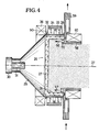
- FIG. 2 shows further details of this particle source.
- This particle source has a container 26 made of quartz, which has a round flat or arched bottom 27 and a cylindrical side wall 28.
- a conical horn 29 connects to the bottom 27 of the container 26 and is flanged to a hollow body 90 made of conductive, non-ferromagnetic material surrounding the container 26.
- An electromagnetic wave is fed into the horn radiator 29 via a coupling element 30 and a coupling pin 31.
- Two permanent magnets 32, 33 are placed around the cylindrical side wall 28, the north pole of one permanent magnet 32 facing the container 26, while the north pole of the other permanent magnet 33 points away from this container 26.
- These permanent magnets 32, 33 which have extremely strong fields and are, for example, of the Vacumax 140 or Vacudyn type, are surrounded by an external iron yoke 34 in order to generate a toroidal magnetic field 35 in the interior of the container serving as a reactor vessel, which provides magnetic induction, that at a given
- Excitation frequency of the microwave field meets the electron cyclotron resonance conditions.
- a horseshoe magnet or electromagnet instead of two permanent magnets, it is also possible to use a horseshoe magnet or electromagnet.
- a plasma of high ionization density is generated within the container 26 using this electron cyclotron resonance (ECR).
- ECR electron cyclotron resonance
- the given excitation frequency of z. B. 2.45 GHz necessary to meet the ECR conditions induction of 875 Gaus results from the toroidal magnetic field 35.
- microwaves and “ECR conditions” in the following, all frequency ranges of electromagnetic radiation are hereby included, with which ECR conditions can be met and as long as excitable modes of the electromagnetic field are propagated.
- the resonance condition does not always have to be met, but it suffices if a not insignificant amplification occurs.
- an additional electromagnet 36 is provided, which is placed around the horn 29, directly after the magnet 32. With the help of this electromagnet, a magnetic field is generated, the field lines of which run essentially parallel to the central axis 37 of the horn radiator 29 and which influences the plasma distribution.
- the extraction device 4 At the outlet of the container 26 is the extraction device 4. This has three extraction grids 38, 39, 40, which are at different potentials. Each of these extraction grids 38, 39, 40 is connected at its edge region to its own carrier 41, 42, 43, which has a cavity 44, 45, 46. This cavity 44, 45, 46 serves to receive a coolant, for. B. of water.
- the water is introduced through openings in the supports 41 to 43 - which is indicated by the arrows 47, 48, 49 - and is led out of the supports 41 to 43 through outflow openings, which is indicated by the arrows 50, 51, 52.
- An electrical insulation layer 53, 54 is provided between two adjacent supports 41, 42 and 42, 43, respectively.
- the carrier 41 which is connected to the grid 38 which is directly opposite the container 26, has a gas inlet 55 which is an integral part of this carrier 41.
- the gas is fed into this gas inlet through at least one bore in the carrier 41.
- the inflow of the gas is indicated by the arrows 56, 57.
- the gas which flows into the container 26 through the gas inlet 55 is ionized by the electromagnetic wave which is emitted by the horn radiator 29. Due to the magnetic field distribution, which is caused by the permanent magnets 32, 33, a "race track" for electrons and ions is formed within the quartz container 26, as is also known from magnetron sputter cathodes. This makes it possible to significantly increase the degree of ionization, which is not yet very large due to the microwave radiation alone.
- the advantage of the toroidal magnetic field over other magnetic fields in the electron cyclotron resonance method is that in the edge region of the container 26, i. H. a magnetic field is created in the effective range of the alternating electromagnetic field, which fulfills the ECR conditions.
- the superimposed magnetic field of the electromagnet 36 causes, depending on the direction of the magnetic field generated, a radial contraction or a radial expansion of the ECR excitation area and serves to control the plasma density distribution in the container 26.
- the plasma located in the container 26, which is indicated by dots in FIG. 2, can only serve as an ion source, electron source or as a source for neutral particles with the aid of special control methods.
- grid 38 is set to positive potential
- grid 39 to negative potential and grid 40 to potential zero (ground) they remain negative charged particles (electrons, negative ions) trapped in the container, while the positively charged particles (positive ions) are sucked off.
- the positive particles are first extracted with a high voltage (sum of the voltages at grid 38 and 39) - this results in a high particle current density - and then decelerated by the potential difference between grid 39 and grid 40 (acceleration, deceleration).
- high ion current densities can be achieved with low ion energy.
- the grid 38 is set to negative potential, the grid 39 to positive potential and the grid 40 to zero potential (mass), the positive particles remain trapped in the container while the negatively charged particles (electrons, negative ions) are drawn off.
- the negative particles are in turn extracted with a high voltage (sum of the voltages between grid 38 and 39), which results in a high particle current density, and slowed down by the potential difference between grid 39 and grid 40.
- Neutral parts can e.g. B. generated by the fact that the grid 38 is at a positive potential, the grid 39 is at a negative potential and the grid 40 is in turn at a positive potential, the potentials must be chosen so high that the grid is considered a barrier for electrically charged particles and only let neutral particles pass through, which, however, are not then accelerated electrically, but only have the speed of the temperature-dependent molecular movement.
- the cooling of the supports 41, 42, 43 by means of water or another medium also cools the grids 38 to 40 themselves. This has the advantage that they do not heat up excessively by impacting plasma particles and are thereby destroyed.
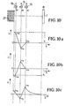
- FIGS. 10a to 10c The voltage profiles which result from the different grid potentials are shown in FIGS. 10a to 10c and are described there again with regard to their effect.
- FIG. 3 shows a perspective view of the container 26 with the permanent magnets 32, 33 surrounding it.
- the toroidal magnetic field for generating the electron cyclotron resonance can clearly be seen here.
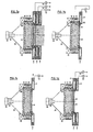
- FIG. 4 shows a further embodiment of the invention, in which the plasma is generated in the same way as in the device according to FIG. 2, but other means are provided for the extraction of the charged particles.
- magnetic fields are used for the extraction.
- annular body 58 which contains the gas supply 55 and which is provided with a cooling device 59, an electromagnet 60 is placed, which generates a magnetic field, the central field lines of which run along the axis 37.
- FIG. 5 shows a further embodiment of the invention, in which the microwave radiation is not coupled in by a horn, but by a suitably dimensioned coaxial waveguide 61 which has an inner conductor 62 and an outer conductor 63.
- a further peculiarity lies in the use of an annular electromagnet 64, which is arranged similarly to the electromagnet 36 of FIG. 2, and in the use of an annular magnet 65, which is arranged in the end piece of the inner conductor 62 of the coaxial waveguide.
- the end piece of the inner conductor 62 of the coaxial waveguide 61 projects with the part which contains the annular magnet 65 into an indentation 68 of the bottom 27 of the container 26.
- the poles of the annular magnet 65 are located completely in the indentation 68 and point to the inside of the container 26 and generate a second toroidal magnetic field inside the container.
- the direction of the magnetic field lines 69 can coincide with the direction of the magnetic field lines 35 or be opposite to them.
- the direction of the magnetic field lines 69 can be selected by appropriate installation of the ring magnets 66, 67 in the bulge 68.
- the use of two toroidal magnetic fields creates two electron racetracks and thus two ring-shaped ECR zones. This allows the density distribution in the plasma space and thus the homogeneity of the particle beam to be extracted to be influenced.
- An intensification of this homogenization effect is also possible in that the electromagnet 64 is provided, which surrounds the end of the outer conductor 63.
- the outer conductor 63 and the inner conductor 62 of the coaxial cable 61 are adapted to the geometry of the container 26.
- the diameter of the outer conductor 63 essentially corresponds to the diameter of the container, while the diameter of the inner conductor 62 essentially corresponds to the diameter of the indentation 68.
- the exemplary embodiment shown in FIG. 6 is a mixed form of the embodiments shown in FIGS. 4 and 5.
- the permanent magnets 32, 33, the electromagnets 36, 60, the gas supply 55 and the cooling device 59 are arranged according to the device according to FIG. 4, while the supply of the microwave energy and the second ECR region are arranged according to the device according to FIG. 5.
- a magnetic field is therefore used for particle extraction in the device according to FIG. 6, this magnetic field being generated by the electromagnets 36 and 60.
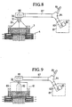
- FIG. 7a shows the ion source according to FIG. 2 again, but now the electrical connections of the grids are shown. It can be seen that the grids each have any potential. These potentials are symbolized by the voltage sources 73, 74, 75.
- FIG. 7b shows an ion source which has only one extraction grid 38 and in which the ions are extracted by means of an alternating voltage.
- the extraction grid 38 consists of conductive material, which can be provided with an insulating coating.
- One pole of an AC voltage source 76 lies on the carrier 41 of the grid 38, the other pole of which is connected to a metal strip 77 which surrounds the side wall 28 in a ring shape.
- a DC voltage extraction with only one DC potential is shown in FIG. 7c.
- a DC voltage source 78 is connected to one terminal and the carrier 41 and thus to the grid 38, while the other terminal of the DC voltage source is connected to ground.
- FIG. 7d shows a direct current two-grid arrangement in which the two grids 38, 39 are each at a certain potential. These potentials are provided by the DC voltage sources 79, 80.
- All DC voltage sources 73, 78, 79, 80 can both be regulated from zero to a specific maximum value and can be switched over with regard to their polarity.
- a microwave generator 81 is provided, which consists of the actual generator 82 and a connector 83.
- This connector is connected to a circulator 84, to which a matching resistor 85 is connected, which serves as a so-called microwave sump.
- the circulator 84 is in turn connected to an impedance transformer 86 via a rectangular waveguide 87.
- This impedance transformer 86 is connected to the horn radiator 29 via a coupling element 30.
- An isolator can be inserted into the coupling member 30 for potential isolation.
- the microwaves are fed in via the coaxial waveguide 61.
- FIG. 10 shows the plasma chamber with the bottom 27, three voltage sources 73, 74, 75, the grids 38, 39, 40 and the sample table 7 in principle.
- the effective acceleration voltage that is present directly at the outlet of the plasma chamber 27 is characterized by the intersection of the dashed lines with the U-axis.
- the potential applied to the grid 38 is positive and slightly less than the effective acceleration voltage. This creates a negative voltage gradient that attracts the positive ions and repels negative electrons.
- the effective acceleration voltage for the extraction of electrons and negative ions is shown in FIG. 10b as the point of intersection of the dashed line with the U-axis.
- This effective voltage is slightly less negative than the voltage on grid 38, so that there is a positive voltage gradient that attracts the electrons and negative ions.
- FIG. 1 A potential curve over the distance between the plasma chamber and sample table 7, with which neutral particles are withdrawn from the plasma chamber 10c is shown in FIG.
- the negative voltage drop between the grid 38 and the exit of the chamber initially pulls positive particles out of the chamber and blocks negative particles. Due to their kinetic energy, neutral particles pass freely through all potential thresholds that are built up by the grids 38, 39, 40.
- the positive particles located between the grids 38, 39 are further accelerated by the negative voltage gradient, at the same time negative particles which had overcome the potential threshold at the grid 38 are accelerated towards the chamber by the positive voltage drop and are thus kept away from the sample table 7.
- There is a strong positive voltage drop between the grids 39 and 40 which decelerates the positive particles and keeps them away from the sample table 7. This means that only neutral particles get onto the sample table.
- the additional electromagnets 66, 67 provided in connection with a coaxial cable can analogously also be provided in an arrangement according to FIGS. 1 to 4, wherein their toroidal fields can protrude into the container 26 both vertically and horizontally.
Landscapes
- Physics & Mathematics (AREA)
- Plasma & Fusion (AREA)
- Engineering & Computer Science (AREA)
- Chemical & Material Sciences (AREA)
- Spectroscopy & Molecular Physics (AREA)
- Analytical Chemistry (AREA)
- Electromagnetism (AREA)
- Optics & Photonics (AREA)
- Plasma Technology (AREA)
- Electron Sources, Ion Sources (AREA)
- Drying Of Semiconductors (AREA)
- Physical Vapour Deposition (AREA)
- ing And Chemical Polishing (AREA)
- Physical Deposition Of Substances That Are Components Of Semiconductor Devices (AREA)
Priority Applications (1)
| Application Number | Priority Date | Filing Date | Title |
|---|---|---|---|
| AT89100449T ATE104089T1 (de) | 1988-02-05 | 1989-01-12 | Teilchenquelle fuer eine reaktive ionenstrahlaetz- oder plasmadepositionsanlage. |
Applications Claiming Priority (2)
| Application Number | Priority Date | Filing Date | Title |
|---|---|---|---|
| DE3803355A DE3803355A1 (de) | 1988-02-05 | 1988-02-05 | Teilchenquelle fuer eine reaktive ionenstrahlaetz- oder plasmadepositionsanlage |
| DE3803355 | 1988-02-05 |
Publications (3)
| Publication Number | Publication Date |
|---|---|
| EP0326824A2 true EP0326824A2 (fr) | 1989-08-09 |
| EP0326824A3 EP0326824A3 (en) | 1990-01-31 |
| EP0326824B1 EP0326824B1 (fr) | 1994-04-06 |
Family
ID=6346638
Family Applications (1)
| Application Number | Title | Priority Date | Filing Date |
|---|---|---|---|
| EP89100449A Expired - Lifetime EP0326824B1 (fr) | 1988-02-05 | 1989-01-12 | Source de particules pour un dispositif réactif d'érosion à faisceau ionique ou de déposition à plasma |
Country Status (7)
| Country | Link |
|---|---|
| US (1) | US4987346A (fr) |
| EP (1) | EP0326824B1 (fr) |
| JP (1) | JPH02103932A (fr) |
| KR (1) | KR920003019B1 (fr) |
| AT (1) | ATE104089T1 (fr) |
| DE (2) | DE3803355A1 (fr) |
| FI (1) | FI95340C (fr) |
Cited By (2)
| Publication number | Priority date | Publication date | Assignee | Title |
|---|---|---|---|---|
| FR2722213A1 (fr) * | 1994-07-05 | 1996-01-12 | Plasmion | Dispositif pour creer un faisceau d'ions d'energie ajustable notamment pour le traitement au defile et sous vide de surfaces de grandes dimensions |
| WO1997004474A1 (fr) * | 1995-07-21 | 1997-02-06 | Applied Materials, Inc. | Appareil a faisceau ionique |
Families Citing this family (50)
| Publication number | Priority date | Publication date | Assignee | Title |
|---|---|---|---|---|
| FR2631199B1 (fr) * | 1988-05-09 | 1991-03-15 | Centre Nat Rech Scient | Reacteur a plasma |
| DE3920835C2 (de) * | 1989-06-24 | 1997-12-18 | Leybold Ag | Einrichtung zum Beschichten von Substraten |
| DE3920834A1 (de) * | 1989-06-24 | 1991-02-21 | Leybold Ag | Mikrowellen-kathodenzerstaeubungseinrichtung |
| US5173641A (en) * | 1990-09-14 | 1992-12-22 | Tokyo Electron Limited | Plasma generating apparatus |
| DE4113142A1 (de) * | 1991-03-14 | 1992-09-17 | Leybold Ag | Vorrichtung zur erzeugung von glimmentladungen |
| US5189446A (en) * | 1991-05-17 | 1993-02-23 | International Business Machines Corporation | Plasma wafer processing tool having closed electron cyclotron resonance |
| US5234526A (en) * | 1991-05-24 | 1993-08-10 | Lam Research Corporation | Window for microwave plasma processing device |
| DE4119362A1 (de) * | 1991-06-12 | 1992-12-17 | Leybold Ag | Teilchenquelle, insbesondere fuer reaktive ionenaetz- und plasmaunterstuetzte cvd-verfahren |
| DE4203632C2 (de) * | 1992-02-08 | 2003-01-23 | Applied Films Gmbh & Co Kg | Vakuumbeschichtungsanlage |
| JPH0653170A (ja) * | 1992-03-18 | 1994-02-25 | Nec Corp | Ecrプラズマエッチング装置 |
| US5783102A (en) * | 1996-02-05 | 1998-07-21 | International Business Machines Corporation | Negative ion deductive source for etching high aspect ratio structures |
| DE19737548A1 (de) * | 1997-08-28 | 1999-03-04 | Inst Oberflaechenmodifizierung | Kipp-, rotier- und thermostatierbare Substratstation zum Ionenstrahlätzen |
| JP2976965B2 (ja) * | 1998-04-02 | 1999-11-10 | 日新電機株式会社 | 成膜方法及び成膜装置 |
| DE19829760B4 (de) * | 1998-07-03 | 2006-10-12 | Institut für Oberflächenmodifizierung e.V. | Koaxialer Mikrowellenapplikator zur Erzeugung eines Plasmas mit automatischer oder manueller Anpassung |
| DE19927806A1 (de) * | 1999-06-18 | 2001-01-04 | Bosch Gmbh Robert | Vorrichtung und Verfahren zum Hochratenätzen eines Substrates mit einer Plasmaätzanlage und Vorrichtung und Verfahren zum Zünden eines Plasmas und Hochregeln oder Pulsen der Plasmaleistung |
| JP4073174B2 (ja) * | 2001-03-26 | 2008-04-09 | 株式会社荏原製作所 | 中性粒子ビーム処理装置 |
| US20030000921A1 (en) * | 2001-06-29 | 2003-01-02 | Ted Liang | Mask repair with electron beam-induced chemical etching |
| DE10243406A1 (de) * | 2002-09-18 | 2004-04-01 | Leybold Optics Gmbh | Plasmaquelle |
| FR2858333B1 (fr) * | 2003-07-31 | 2006-12-08 | Cit Alcatel | Procede et dispositif pour le depot peu agressif de films dielectriques en phase vapeur assiste par plasma |
| US7421973B2 (en) * | 2003-11-06 | 2008-09-09 | Axcelis Technologies, Inc. | System and method for performing SIMOX implants using an ion shower |
| US7748344B2 (en) * | 2003-11-06 | 2010-07-06 | Axcelis Technologies, Inc. | Segmented resonant antenna for radio frequency inductively coupled plasmas |
| US20050266173A1 (en) * | 2004-05-26 | 2005-12-01 | Tokyo Electron Limited | Method and apparatus of distributed plasma processing system for conformal ion stimulated nanoscale deposition process |
| DE102004039969A1 (de) * | 2004-08-18 | 2006-02-23 | Leybold Optics Gmbh | Plasmaquellenvorrichtung, Anordnung mit einer Plasmaquellenvorrichtung sowie Abstrahleinheit für eine Plasmaquellenvorrichtung |
| JP2006079924A (ja) * | 2004-09-09 | 2006-03-23 | Tdk Corp | イオンビーム照射装置及び当該装置用絶縁スペーサ |
| US7105840B2 (en) * | 2005-02-03 | 2006-09-12 | Axcelis Technologies, Inc. | Ion source for use in an ion implanter |
| JP4099181B2 (ja) * | 2005-07-11 | 2008-06-11 | Tdk株式会社 | イオンビームエッチング方法及びイオンビームエッチング装置 |
| JP5313893B2 (ja) * | 2006-07-20 | 2013-10-09 | エスピーティーエス テクノロジーズ イーティー リミティド | イオンデポジション装置 |
| EP2044610B1 (fr) * | 2006-07-20 | 2012-11-28 | SPP Process Technology Systems UK Limited | Sources de plasma |
| WO2008009898A1 (fr) * | 2006-07-20 | 2008-01-24 | Aviza Technology Limited | Sources d'ions |
| US20080090022A1 (en) * | 2006-10-12 | 2008-04-17 | Energy Conversion Devices, Inc. | High rate, continuous deposition of high quality amorphous, nanocrystalline, microcrystalline or polycrystalline materials |
| EP2188411B1 (fr) * | 2007-08-30 | 2011-10-26 | Koninklijke Philips Electronics N.V. | Système de pulvérisation cathodique |
| JP2009267203A (ja) * | 2008-04-28 | 2009-11-12 | Panasonic Corp | プラズマドーピング装置 |
| CN105101604A (zh) * | 2010-07-16 | 2015-11-25 | 财团法人工业技术研究院 | 电子回旋共振磁性模块与电子回旋共振装置 |
| CN103262663B (zh) * | 2011-04-28 | 2016-12-14 | 住友理工株式会社 | 微波等离子体生成装置和采用该装置的磁控溅射成膜装置 |
| US20130098553A1 (en) * | 2011-10-20 | 2013-04-25 | Applied Materials, Inc. | Electron beam plasma source with profiled chamber wall for uniform plasma generation |
| US20130098552A1 (en) * | 2011-10-20 | 2013-04-25 | Applied Materials, Inc. | E-beam plasma source with profiled e-beam extraction grid for uniform plasma generation |
| US20130098872A1 (en) * | 2011-10-20 | 2013-04-25 | Applied Materials, Inc. | Switched electron beam plasma source array for uniform plasma production |
| JP5907701B2 (ja) * | 2011-11-18 | 2016-04-26 | 住友理工株式会社 | フィルム部材の製造方法 |
| US9443700B2 (en) | 2013-03-12 | 2016-09-13 | Applied Materials, Inc. | Electron beam plasma source with segmented suppression electrode for uniform plasma generation |
| KR101427720B1 (ko) * | 2013-03-27 | 2014-08-13 | (주)트리플코어스코리아 | 단차부 및 블록부를 이용한 플라즈마 도파관 |
| US20140356768A1 (en) * | 2013-05-29 | 2014-12-04 | Banqiu Wu | Charged beam plasma apparatus for photomask manufacture applications |
| DE102013219199A1 (de) * | 2013-09-24 | 2015-03-26 | Fraunhofer-Gesellschaft zur Förderung der angewandten Forschung e.V. | Neues Bewitterungsverfahren für Proben |
| GB201319438D0 (en) * | 2013-11-04 | 2013-12-18 | Univ Lancaster | Waveguide |
| US9799491B2 (en) * | 2015-10-29 | 2017-10-24 | Applied Materials, Inc. | Low electron temperature etch chamber with independent control over plasma density, radical composition and ion energy for atomic precision etching |
| US20170140900A1 (en) * | 2015-11-13 | 2017-05-18 | Applied Materials, Inc. | Uniform low electron temperature plasma source with reduced wafer charging and independent control over radical composition |
| EP3217771B1 (fr) * | 2016-03-11 | 2019-01-09 | Deutsches Elektronen-Synchrotron DESY | Appareil accélérateur de particules chargées, canon à particules chargées et procédé d'accélération de particules chargées |
| EP3309815B1 (fr) * | 2016-10-12 | 2019-03-20 | Meyer Burger (Germany) AG | Dispositif de traitement au plasma comprenant deux sources de plasma excitées par micro-ondes couplées ensemble et procédé de fonctionnement d'un tel dispositif de traitement au plasma |
| US11037765B2 (en) * | 2018-07-03 | 2021-06-15 | Tokyo Electron Limited | Resonant structure for electron cyclotron resonant (ECR) plasma ionization |
| ES2696227B2 (es) * | 2018-07-10 | 2019-06-12 | Centro De Investig Energeticas Medioambientales Y Tecnologicas Ciemat | Fuente de iones interna para ciclotrones de baja erosion |
| KR102773476B1 (ko) * | 2019-10-10 | 2025-02-27 | 삼성전자주식회사 | 전자 빔 발생기, 이를 갖는 플라즈마 처리 장치 및 이를 이용한 플라즈마 처리 방법 |
Family Cites Families (35)
| Publication number | Priority date | Publication date | Assignee | Title |
|---|---|---|---|---|
| DE252916C (fr) * | ||||
| FR2147497A5 (fr) * | 1971-07-29 | 1973-03-09 | Commissariat Energie Atomique | |
| JPS5211175A (en) * | 1975-07-18 | 1977-01-27 | Toshiba Corp | Activated gas reacting apparatus |
| DE2944467A1 (de) * | 1979-11-03 | 1981-05-14 | Kernforschungszentrum Karlsruhe Gmbh, 7500 Karlsruhe | Plasma- und ionenquelle |
| CA1159012A (fr) * | 1980-05-02 | 1983-12-20 | Seitaro Matsuo | Dispositif de deposition de plasma |
| JPS5779621A (en) * | 1980-11-05 | 1982-05-18 | Mitsubishi Electric Corp | Plasma processing device |
| JPS5782955A (en) * | 1980-11-12 | 1982-05-24 | Hitachi Ltd | Microwave plasma generating apparatus |
| JPS58111727A (ja) * | 1981-12-24 | 1983-07-02 | Seikosha Co Ltd | 光ビ−ムの照射位置検出装置 |
| JPH0635323B2 (ja) * | 1982-06-25 | 1994-05-11 | 株式会社日立製作所 | 表面処理方法 |
| JPH06105597B2 (ja) * | 1982-08-30 | 1994-12-21 | 株式会社日立製作所 | マイクロ波プラズマ源 |
| EP0103461B1 (fr) * | 1982-09-10 | 1988-11-17 | Nippon Telegraph And Telephone Corporation | Appareil et procédé de dépôt à plasma |
| JPS59119729A (ja) * | 1982-12-25 | 1984-07-11 | Fujitsu Ltd | マイクロ波処理方法及び装置 |
| US4507588A (en) * | 1983-02-28 | 1985-03-26 | Board Of Trustees Operating Michigan State University | Ion generating apparatus and method for the use thereof |
| US4585668A (en) * | 1983-02-28 | 1986-04-29 | Michigan State University | Method for treating a surface with a microwave or UHF plasma and improved apparatus |
| US4691662A (en) * | 1983-02-28 | 1987-09-08 | Michigan State University | Dual plasma microwave apparatus and method for treating a surface |
| JPS59194407A (ja) * | 1983-04-19 | 1984-11-05 | Ulvac Corp | 電子サイクロトロン共鳴形イオン源用磁石装置 |
| JPS60103626A (ja) * | 1983-11-11 | 1985-06-07 | Hitachi Ltd | プラズマ陽極酸化装置 |
| JPH0627323B2 (ja) * | 1983-12-26 | 1994-04-13 | 株式会社日立製作所 | スパツタリング方法及びその装置 |
| JPS60243955A (ja) * | 1984-05-18 | 1985-12-03 | Hitachi Ltd | マイクロ波イオン源 |
| JPH0616384B2 (ja) * | 1984-06-11 | 1994-03-02 | 日本電信電話株式会社 | マイクロ波イオン源 |
| US4630566A (en) * | 1984-08-16 | 1986-12-23 | Board Of Trustees Operating Michigan State University | Microwave or UHF plasma improved apparatus |
| JPS61131450A (ja) * | 1984-11-30 | 1986-06-19 | Canon Inc | ドライエツチング装置 |
| EP0197668B1 (fr) * | 1985-03-14 | 1989-10-04 | Denton Vacuum Inc | Canon pour production d'un plasma externe |
| US4739170A (en) * | 1985-05-09 | 1988-04-19 | The Commonwealth Of Australia | Plasma generator |
| JP2543846B2 (ja) * | 1985-06-28 | 1996-10-16 | 株式会社ユニシアジェックス | 内燃機関のバルブタイミング調整装置の組立方法 |
| FR2583250B1 (fr) * | 1985-06-07 | 1989-06-30 | France Etat | Procede et dispositif d'excitation d'un plasma par micro-ondes a la resonance cyclotronique electronique |
| JPH0658909B2 (ja) * | 1985-07-15 | 1994-08-03 | 株式会社日立製作所 | 低温プラズマによる成膜方法及び装置 |
| JPS6276137A (ja) * | 1985-09-30 | 1987-04-08 | Hitachi Ltd | イオン源 |
| JPH0654644B2 (ja) * | 1985-10-04 | 1994-07-20 | 株式会社日立製作所 | イオン源 |
| DD248904A1 (de) * | 1986-04-10 | 1987-08-19 | Karl Marx Stadt Tech Hochschul | Mikrowellen-breitstrahl-ionenquelle |
| US4788473A (en) * | 1986-06-20 | 1988-11-29 | Fujitsu Limited | Plasma generating device with stepped waveguide transition |
| DD252916A1 (de) * | 1986-09-23 | 1987-12-30 | Karl Marx Stadt Tech Hochschul | Mikrowellen-plasmaionenquelle |
| US4767931A (en) * | 1986-12-17 | 1988-08-30 | Hitachi, Ltd. | Ion beam apparatus |
| KR880013424A (ko) * | 1987-04-08 | 1988-11-30 | 미타 가츠시게 | 플라즈머 장치 |
| JPH01132033A (ja) * | 1987-11-17 | 1989-05-24 | Hitachi Ltd | イオン源及び薄膜形成装置 |
-
1988
- 1988-02-05 DE DE3803355A patent/DE3803355A1/de active Granted
-
1989
- 1989-01-12 EP EP89100449A patent/EP0326824B1/fr not_active Expired - Lifetime
- 1989-01-12 AT AT89100449T patent/ATE104089T1/de not_active IP Right Cessation
- 1989-01-12 DE DE89100449T patent/DE58907368D1/de not_active Expired - Fee Related
- 1989-01-18 US US07/298,488 patent/US4987346A/en not_active Expired - Fee Related
- 1989-01-25 KR KR1019890000773A patent/KR920003019B1/ko not_active Expired
- 1989-02-02 FI FI890497A patent/FI95340C/fi not_active IP Right Cessation
- 1989-02-06 JP JP1027329A patent/JPH02103932A/ja active Pending
Cited By (6)
| Publication number | Priority date | Publication date | Assignee | Title |
|---|---|---|---|---|
| FR2722213A1 (fr) * | 1994-07-05 | 1996-01-12 | Plasmion | Dispositif pour creer un faisceau d'ions d'energie ajustable notamment pour le traitement au defile et sous vide de surfaces de grandes dimensions |
| WO1996001490A1 (fr) * | 1994-07-05 | 1996-01-18 | Plasmion | Dispositif pour creer un faisceau d'ions d'energie ajustable notamment pour le traitement au defile et sous vide de surfaces de grandes dimensions |
| US5754008A (en) * | 1994-07-05 | 1998-05-19 | Plasmion | Device for creating a beam of adjustable-energy ions particularly for sequential vacuum treatment of surfaces with large dimensions |
| WO1997004474A1 (fr) * | 1995-07-21 | 1997-02-06 | Applied Materials, Inc. | Appareil a faisceau ionique |
| US5920076A (en) * | 1995-07-21 | 1999-07-06 | Applied Materials, Inc. | Ion beam apparatus |
| EP1178517A1 (fr) * | 1995-07-21 | 2002-02-06 | Applied Materials, Inc. | Appareil à faisceau d'ions |
Also Published As
| Publication number | Publication date |
|---|---|
| DE58907368D1 (de) | 1994-05-11 |
| KR920003019B1 (ko) | 1992-04-13 |
| US4987346A (en) | 1991-01-22 |
| KR890013968A (ko) | 1989-09-26 |
| JPH02103932A (ja) | 1990-04-17 |
| DE3803355A1 (de) | 1989-08-17 |
| FI890497L (fi) | 1989-08-06 |
| FI890497A0 (fi) | 1989-02-02 |
| ATE104089T1 (de) | 1994-04-15 |
| EP0326824A3 (en) | 1990-01-31 |
| EP0326824B1 (fr) | 1994-04-06 |
| FI95340B (fi) | 1995-09-29 |
| DE3803355C2 (fr) | 1990-04-05 |
| FI95340C (fi) | 1996-01-10 |
Similar Documents
| Publication | Publication Date | Title |
|---|---|---|
| EP0326824B1 (fr) | Source de particules pour un dispositif réactif d'érosion à faisceau ionique ou de déposition à plasma | |
| DE69019741T2 (de) | Ionenstrahlkanone. | |
| DE60130945T2 (de) | Verfahren und Vorrichtung zur Mikrowellenanregung eines Plasmas in einer Ionenstrahlführungsvorrichtung | |
| DE3920835C2 (de) | Einrichtung zum Beschichten von Substraten | |
| DE69033908T2 (de) | Plasmadepositions- und Ätzungsanlage mit hoher Dichte | |
| DE69325650T2 (de) | Einrichtung zur Erzeugung magnetischer Felder in Arbeitsspalten, die zur Bestrahlung einer Fläche mit atomaren und molekularen Ionen nutzbar sind | |
| DE3783432T2 (de) | End-hall-ionenquelle. | |
| DE69218924T2 (de) | System zur Erzeugung eines Plasmas mit hoher Dichte | |
| DE68921370T2 (de) | Electronzyklotronresonanz-Ionenquelle. | |
| DE68924413T2 (de) | Radiofrequenzinduktion/Mehrpolplasma-Bearbeitungsvorrichtung. | |
| DE69123531T2 (de) | Plasma-Bearbeitungsgerät unter Verwendung eines mittels Mikrowellen erzeugten Plasmas | |
| DE69421157T2 (de) | Plasmastrahl-Erzeugungsverfahren und Vorrichtung die einen Hochleistungsplasmastrahl erzeugen Kann | |
| CH696972A5 (de) | Vorrichtung zur Kathodenzerstäubung. | |
| DE2608415A1 (de) | Verfahren zur beschichtung eines substrats mit einer lage polymeren materials | |
| EP0876677A1 (fr) | Source ionique pour systeme a faisceau ionique | |
| DE69405546T2 (de) | Lineare mikrowellenquelle zur plasmabehandlung von flächen. | |
| DE69112166T2 (de) | Plasmaquellenvorrichtung für Ionenimplantierung. | |
| DE3586176T2 (de) | Mikrowellenelektronenkanone. | |
| DE69812830T2 (de) | Vorrichtung zur Erzeugung eines ausgedehnten Induktionsplasmas für Plasmabehandlungen | |
| DE3688860T2 (de) | Mittels Elektronenstrahl angeregte Ionenstrahlquelle. | |
| EP2425445B1 (fr) | Procédé de production d'un jet de plasma et source de plasma | |
| EP1444874B1 (fr) | Systeme permettant de produire un plasma local micro-ondes a basse pression a la resonance electronique cyclotronique dans un emplacement predefini a l'interieur de la chambre de traitement dudit systeme | |
| DE4239843A1 (de) | Vorrichtung für die Erzeugung von Plasma, insbesondere zum Beschichten von Substraten | |
| DE1489020B2 (de) | Beschleuniger fuer geladene teilchen | |
| WO1994003919A1 (fr) | Procede de production de faisceaux de n'importe quels ions hautement charges, de faible energie cinetique et dispositif de mise en ×uvre dudit procede |
Legal Events
| Date | Code | Title | Description |
|---|---|---|---|
| PUAI | Public reference made under article 153(3) epc to a published international application that has entered the european phase |
Free format text: ORIGINAL CODE: 0009012 |
|
| AK | Designated contracting states |
Kind code of ref document: A2 Designated state(s): AT CH DE FR GB IT LI NL SE |
|
| PUAL | Search report despatched |
Free format text: ORIGINAL CODE: 0009013 |
|
| AK | Designated contracting states |
Kind code of ref document: A3 Designated state(s): AT CH DE FR GB IT LI NL SE |
|
| 17P | Request for examination filed |
Effective date: 19900228 |
|
| 17Q | First examination report despatched |
Effective date: 19920702 |
|
| GRAA | (expected) grant |
Free format text: ORIGINAL CODE: 0009210 |
|
| AK | Designated contracting states |
Kind code of ref document: B1 Designated state(s): AT CH DE FR GB IT LI NL SE |
|
| REF | Corresponds to: |
Ref document number: 104089 Country of ref document: AT Date of ref document: 19940415 Kind code of ref document: T |
|
| REF | Corresponds to: |
Ref document number: 58907368 Country of ref document: DE Date of ref document: 19940511 |
|
| GBT | Gb: translation of ep patent filed (gb section 77(6)(a)/1977) |
Effective date: 19940419 |
|
| ITF | It: translation for a ep patent filed | ||
| ET | Fr: translation filed | ||
| EAL | Se: european patent in force in sweden |
Ref document number: 89100449.1 |
|
| PLBE | No opposition filed within time limit |
Free format text: ORIGINAL CODE: 0009261 |
|
| STAA | Information on the status of an ep patent application or granted ep patent |
Free format text: STATUS: NO OPPOSITION FILED WITHIN TIME LIMIT |
|
| 26N | No opposition filed | ||
| PGFP | Annual fee paid to national office [announced via postgrant information from national office to epo] |
Ref country code: FR Payment date: 19961209 Year of fee payment: 9 |
|
| PGFP | Annual fee paid to national office [announced via postgrant information from national office to epo] |
Ref country code: AT Payment date: 19961212 Year of fee payment: 9 |
|
| PGFP | Annual fee paid to national office [announced via postgrant information from national office to epo] |
Ref country code: SE Payment date: 19961217 Year of fee payment: 9 |
|
| PGFP | Annual fee paid to national office [announced via postgrant information from national office to epo] |
Ref country code: DE Payment date: 19961218 Year of fee payment: 9 |
|
| PGFP | Annual fee paid to national office [announced via postgrant information from national office to epo] |
Ref country code: GB Payment date: 19961219 Year of fee payment: 9 |
|
| PGFP | Annual fee paid to national office [announced via postgrant information from national office to epo] |
Ref country code: NL Payment date: 19961223 Year of fee payment: 9 |
|
| PGFP | Annual fee paid to national office [announced via postgrant information from national office to epo] |
Ref country code: CH Payment date: 19970107 Year of fee payment: 9 |
|
| PG25 | Lapsed in a contracting state [announced via postgrant information from national office to epo] |
Ref country code: GB Free format text: LAPSE BECAUSE OF NON-PAYMENT OF DUE FEES Effective date: 19980112 Ref country code: AT Free format text: LAPSE BECAUSE OF NON-PAYMENT OF DUE FEES Effective date: 19980112 |
|
| PG25 | Lapsed in a contracting state [announced via postgrant information from national office to epo] |
Ref country code: SE Free format text: LAPSE BECAUSE OF NON-PAYMENT OF DUE FEES Effective date: 19980113 |
|
| PG25 | Lapsed in a contracting state [announced via postgrant information from national office to epo] |
Ref country code: LI Free format text: LAPSE BECAUSE OF NON-PAYMENT OF DUE FEES Effective date: 19980131 Ref country code: FR Free format text: THE PATENT HAS BEEN ANNULLED BY A DECISION OF A NATIONAL AUTHORITY Effective date: 19980131 Ref country code: CH Free format text: LAPSE BECAUSE OF NON-PAYMENT OF DUE FEES Effective date: 19980131 |
|
| PG25 | Lapsed in a contracting state [announced via postgrant information from national office to epo] |
Ref country code: NL Free format text: LAPSE BECAUSE OF NON-PAYMENT OF DUE FEES Effective date: 19980801 |
|
| GBPC | Gb: european patent ceased through non-payment of renewal fee |
Effective date: 19980112 |
|
| REG | Reference to a national code |
Ref country code: CH Ref legal event code: PL |
|
| NLV4 | Nl: lapsed or anulled due to non-payment of the annual fee |
Effective date: 19980801 |
|
| PG25 | Lapsed in a contracting state [announced via postgrant information from national office to epo] |
Ref country code: DE Free format text: LAPSE BECAUSE OF NON-PAYMENT OF DUE FEES Effective date: 19981001 |
|
| EUG | Se: european patent has lapsed |
Ref document number: 89100449.1 |
|
| REG | Reference to a national code |
Ref country code: FR Ref legal event code: ST |
|
| PG25 | Lapsed in a contracting state [announced via postgrant information from national office to epo] |
Ref country code: IT Free format text: LAPSE BECAUSE OF NON-PAYMENT OF DUE FEES;WARNING: LAPSES OF ITALIAN PATENTS WITH EFFECTIVE DATE BEFORE 2007 MAY HAVE OCCURRED AT ANY TIME BEFORE 2007. THE CORRECT EFFECTIVE DATE MAY BE DIFFERENT FROM THE ONE RECORDED. Effective date: 20050112 |