EP0326921A2 - Dispositif pour la connexion d'un adaptateur non approprié sur un rail de courant - Google Patents
Dispositif pour la connexion d'un adaptateur non approprié sur un rail de courant Download PDFInfo
- Publication number
- EP0326921A2 EP0326921A2 EP89101253A EP89101253A EP0326921A2 EP 0326921 A2 EP0326921 A2 EP 0326921A2 EP 89101253 A EP89101253 A EP 89101253A EP 89101253 A EP89101253 A EP 89101253A EP 0326921 A2 EP0326921 A2 EP 0326921A2
- Authority
- EP
- European Patent Office
- Prior art keywords
- adapter
- busbar
- selector shaft
- contact
- fastening lugs
- Prior art date
- Legal status (The legal status is an assumption and is not a legal conclusion. Google has not performed a legal analysis and makes no representation as to the accuracy of the status listed.)
- Withdrawn
Links
- 239000011810 insulating material Substances 0.000 claims abstract description 4
- 210000002105 tongue Anatomy 0.000 claims abstract description 4
- 239000004020 conductor Substances 0.000 claims abstract 6
- 230000007935 neutral effect Effects 0.000 claims abstract 2
- 230000000903 blocking effect Effects 0.000 claims description 2
- 238000003780 insertion Methods 0.000 abstract description 3
- 230000037431 insertion Effects 0.000 abstract description 3
- 241001295925 Gegenes Species 0.000 description 1
- 230000001681 protective effect Effects 0.000 description 1
Images

Classifications
-
- H—ELECTRICITY
- H01—ELECTRIC ELEMENTS
- H01R—ELECTRICALLY-CONDUCTIVE CONNECTIONS; STRUCTURAL ASSOCIATIONS OF A PLURALITY OF MUTUALLY-INSULATED ELECTRICAL CONNECTING ELEMENTS; COUPLING DEVICES; CURRENT COLLECTORS
- H01R25/00—Coupling parts adapted for simultaneous co-operation with two or more identical counterparts, e.g. for distributing energy to two or more circuits
- H01R25/14—Rails or bus-bars constructed so that the counterparts can be connected thereto at any point along their length
- H01R25/142—Their counterparts
Definitions
- busbars or power take-off bars or light bars are known to which consumers, in particular lamps, lights, spotlights and the like, can be mechanically and electrically connected by means of adapters adapted to the respective busbars.
- a consumer can only be mechanically and electrically connected to a power rail if it is provided with an adapter that matches this power rail.
- the invention is based on the object of providing a device with the aid of which it is possible to connect a consumer provided with an adapter to a busbar which does not match the adapter of the consumer.
- a consumer which is provided with an adapter that does not fit the busbar, can be reliably connected mechanically and electrically to this busbar.
- the adapter of the consumer can only be inserted into the receiving space of the device when the selector shaft has already established a reliable mechanical and electrical connection between the device and the busbar.
- the fastening lugs of the device are integrally connected to the switching shaft and the inwardly projecting ribs of the receiving space are integrally connected to the switching shaft, so that the load of the consumer is transmitted to the busbar via the switching shaft.
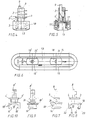
- the device for connecting the busbar 20 to an adapter 21 that is not adapted to this busbar 20 consists of a housing 1 made of insulating material, which has an engagement part 2 and a receiving part 3.
- the housing 1 can be inserted with the engaging part 2 into the receiving channel of the busbar 20.
- fastening lugs 4 and 5 and contact fingers 6, 7 and 7 ' can be moved out.
- the mounting lugs 4, 5 and 4 'and 5' and the contact fingers 6 and 7, 7 ' can be brought into an inserted position and into a connecting position by means of rotatable switching shafts 8 and 8'.
- a second control shaft 8 ' is provided, which with the fastening lugs 4' and 5 'produce an additional mechanical connection to the busbar 20. Furthermore, depending on the position of the control shaft 8 'contact finger 7 or the contact finger 7' can tap a further phase line of the busbar 20.
- an earth contact finger 9 is arranged on the engaging part 2 and is supported against a spring 25. Furthermore, an earth contact finger 9 'is provided, which, depending on the design of the busbar, bears against an earth protection line which is arranged at the open end of the receiving channel of the busbar 20.
- the housing 1 is further provided with a receiving part 3 that bears against the busbar 20 and has a receiving space 13 into which an adapter 21 connected to a consumer can be inserted.
- 13 ribs 14 and 15 or 14 'and 15' are provided on the longitudinal inner walls of the receiving space, which cooperate for mechanical connection of the adapter 21 to the housing 1 with fastening lugs of the adapter 21.
- openings are provided, behind which contact strips 16, 17, 17 'are arranged, which are connected to the contact fingers 6, 7 and 7' and to which for the electrical connection of the adapter 21, the contact tongues of the adapter 21st can be created.
- the selector shaft 8 is provided with a locking part 22 which, when in use the control shaft 8 protrudes into the receiving space 13 and in the connected position of the control shaft 8 releases this receiving space 13 for inserting the adapters 21.
- the control shaft 8 is rotatable about an axis 12 running at right angles to the busbar 20 and has a cylindrical switching head 18 which is provided with a continuous recess 19.
- the continuous recess 19 leaves two side cheeks 22 and 23 of the cylindrical switching head 18. These side cheeks 22 and 23 protrude as a blocking part into the receiving space 13 when the selector shaft is in the operating position.
- the device can also connect heavier consumers to the busbar 20, it is equipped with two parallel switching shafts 8 and 8 '.
- the second control shaft 8 ' is designed in accordance with the first control shaft 8.
- the mounting tabs 4 'and 5' are integrally connected to the selector shaft 8 '.
- the cross section 19 'of the control shaft 8' corresponds essentially to the cross section of the receiving space 13.
- the control shaft 8 ' is provided with ribs 14' and 15 'projecting into the receiving space 13, which cooperate with fastening lugs of the adapter to be used in the device.
- the switching heads 18, 18 'of the switching shafts 8 and 8' can be rotated by hand from the inserted position by 90 ° into the connection position.
- the switch heads 18, 18 'slots 24 and 24' are provided, in which screws 4 can be used to rotate the switching shafts 8 and 8 'in the insertion position or in the connection position.
- the receiving space 13 is designed such that, as shown in FIG. 1, it can accommodate a short adapter 21, which engages with its fastening lugs over the ribs 14 and 15 on the selector shaft 8.
- a long adapter can also be used, the engaging part of which is designed in cross section as well as for an engaging part of the short adapter and which in turn has a further pair of fastening lugs which, in the connected position, have inwardly directed ribs 14 'and 15' the control shaft 8 'grab.
Landscapes
- Connector Housings Or Holding Contact Members (AREA)
- Connections Arranged To Contact A Plurality Of Conductors (AREA)
- Details Of Connecting Devices For Male And Female Coupling (AREA)
Applications Claiming Priority (2)
| Application Number | Priority Date | Filing Date | Title |
|---|---|---|---|
| DE8801153U | 1988-02-01 | ||
| DE8801153U DE8801153U1 (de) | 1988-02-01 | 1988-02-01 | Vorrichtung zum Verbinden einer Stromschiene mit einem an diese nicht angepaßten Adapter |
Publications (2)
| Publication Number | Publication Date |
|---|---|
| EP0326921A2 true EP0326921A2 (fr) | 1989-08-09 |
| EP0326921A3 EP0326921A3 (fr) | 1990-06-27 |
Family
ID=6820147
Family Applications (1)
| Application Number | Title | Priority Date | Filing Date |
|---|---|---|---|
| EP89101253A Withdrawn EP0326921A3 (fr) | 1988-02-01 | 1989-01-25 | Dispositif pour la connexion d'un adaptateur non approprié sur un rail de courant |
Country Status (2)
| Country | Link |
|---|---|
| EP (1) | EP0326921A3 (fr) |
| DE (1) | DE8801153U1 (fr) |
Cited By (1)
| Publication number | Priority date | Publication date | Assignee | Title |
|---|---|---|---|---|
| WO2005020387A1 (fr) * | 2003-08-18 | 2005-03-03 | Moir, Michael, Christopher | Prise electrique et systeme de barre omnibus |
Families Citing this family (2)
| Publication number | Priority date | Publication date | Assignee | Title |
|---|---|---|---|---|
| FR2639410A1 (fr) * | 1988-11-23 | 1990-05-25 | Etudes Realis Qualite Habitat | Ensemble de fixation d'un organe fonctionnel sur une structure de support quelconque |
| DE9017281U1 (de) * | 1990-12-21 | 1991-04-11 | Semperlux GmbH Lichttechnisches Werk, 1000 Berlin | Adapter zwischen einer Stromschiene und einem Stromverbraucher |
Family Cites Families (15)
| Publication number | Priority date | Publication date | Assignee | Title |
|---|---|---|---|---|
| US2399408A (en) * | 1943-04-20 | 1946-04-30 | Walk Udell Clifford | Electrical convenience outlet |
| US3503032A (en) * | 1968-01-04 | 1970-03-24 | Us Industries Inc | Adaptor for electrical power distribution track |
| DE2104274A1 (de) * | 1970-02-03 | 1971-08-12 | Nokia Oy Ab | Anschlußstecker |
| DE7022809U (de) * | 1970-06-18 | 1972-01-27 | Reininghaus & Co | Beleuchtungsvorrichtung |
| CH528048A (de) * | 1970-10-28 | 1972-09-15 | Reininghaus & Co | Beleuchtungsvorrichtung |
| DE2155732A1 (de) * | 1970-11-12 | 1972-06-22 | Staff & Schwarz Gmbh | Adapter |
| GB1407589A (en) * | 1971-11-25 | 1975-09-24 | Rotaflex Ltd | Electrical power distribution equipment |
| DE2212327A1 (de) * | 1972-03-15 | 1973-09-27 | Staff & Schwarz Gmbh | Adapter fuer stromabnehmer, wie leuchten, elektrische geraete od. dgl |
| GB1499795A (en) * | 1974-02-27 | 1978-02-01 | Rotaflex Ltd | Electrical current supply installations |
| DE2411976C2 (de) * | 1974-03-13 | 1983-05-11 | Erco Leuchten GmbH, 5880 Lüdenscheid | Adapter für ein- oder mehrphasige Stromentnahmeschienen |
| NO138121C (no) * | 1976-05-14 | 1978-07-05 | Kokvik Bjoern | Anordning ved koplingsstykke for stroemskinner |
| DE2810681C2 (de) * | 1978-03-11 | 1982-04-08 | Erco Leuchten GmbH, 5880 Lüdenscheid | Adapter für ein- oder mehrphasige Stromentnahmeschienen |
| FI821643A7 (fi) * | 1982-05-10 | 1983-11-11 | Nokia Oy Ab | Kannatin- ja virransyöttölaite loistevalaisimia varten. |
| IT8321669U1 (it) * | 1983-04-28 | 1984-10-28 | Profilux Srl | Struttura di adattatore bipolare per linee elettriche multipolari di tipo blindato facenti parte di impianti per l'illuminazione di interni |
| DE8800307U1 (de) * | 1988-01-13 | 1988-03-03 | Raak Licht B.V., Aalsmeer | Adapter mit Transformator |
-
1988
- 1988-02-01 DE DE8801153U patent/DE8801153U1/de not_active Expired
-
1989
- 1989-01-25 EP EP89101253A patent/EP0326921A3/fr not_active Withdrawn
Cited By (1)
| Publication number | Priority date | Publication date | Assignee | Title |
|---|---|---|---|---|
| WO2005020387A1 (fr) * | 2003-08-18 | 2005-03-03 | Moir, Michael, Christopher | Prise electrique et systeme de barre omnibus |
Also Published As
| Publication number | Publication date |
|---|---|
| DE8801153U1 (de) | 1988-08-18 |
| EP0326921A3 (fr) | 1990-06-27 |
Similar Documents
| Publication | Publication Date | Title |
|---|---|---|
| DE1911315C3 (de) | Elektrisches Stromverteilungssystem | |
| DE19835459C2 (de) | Anschlußklemme für elektrische Leiter | |
| DE102006003064A1 (de) | Elektrischer Reihenklemmenblock | |
| EP0504703A2 (fr) | Prothèse auditive avec des moyens électriques de contact disposés dans un compartiment pour pile | |
| DE69311591T2 (de) | Anschlussvorrichtung für einen Niederspannungsschalter mit Kunststoffgehäuse | |
| DE2754581C2 (de) | Elektrisches Verbindungselement | |
| EP0532881A2 (fr) | Dispositif pour la connexion électrique de rails conducteurs disposés parallelement | |
| DE1603326B2 (de) | Spielbaustein | |
| EP3016215A1 (fr) | Dispositif de mise a la terre de rails | |
| DE69923506T2 (de) | Elektrisches Verbindungsgehäuse | |
| DE10205470C1 (de) | Anschlusskontakt | |
| EP0326921A2 (fr) | Dispositif pour la connexion d'un adaptateur non approprié sur un rail de courant | |
| DE3010039C2 (de) | Vorrichtung zum Verbinden zweier Sammelschienensysteme | |
| DE9212342U1 (de) | Schraubenlose elektrische Klemme | |
| DE3641153C2 (fr) | ||
| DE4411731B4 (de) | Aufputz-Steckdose | |
| DE2929382C2 (de) | Kippriegel-Verschlußbeschlag für Kipp-Schwenk-Fenster, -Türen o. dgl. | |
| EP0890971A2 (fr) | Couvercle pour contacts de fusibles dans les dispositifs à fusibles du type basse tension haute puissance | |
| DE102006022640A1 (de) | Adapter, Anschlusseinheit, Anordnung eines Leuchtmittels an einer Schiene, Beleuchtungssystem und Verfahren zum Installieren eines Beleuchtungssystems | |
| EP0547532A1 (fr) | Disposition avec un module BCU et moyens pour connexion séparable aux lignes-BUS | |
| DE2451810A1 (de) | Reihenklemme | |
| DE3617113C2 (fr) | ||
| DE9201816U1 (de) | Abgangskasten, insbesondere für Schienenverteiler | |
| EP0890970B1 (fr) | Couvercle pour contacts de fusibles dans les dispositifs à fusibles du type basse tension haute puissance | |
| EP0359939A2 (fr) | Ressort à air avec dispositif de fixation à une conduite |
Legal Events
| Date | Code | Title | Description |
|---|---|---|---|
| PUAI | Public reference made under article 153(3) epc to a published international application that has entered the european phase |
Free format text: ORIGINAL CODE: 0009012 |
|
| AK | Designated contracting states |
Kind code of ref document: A2 Designated state(s): AT BE CH DE ES FR IT LI LU NL SE |
|
| PUAL | Search report despatched |
Free format text: ORIGINAL CODE: 0009013 |
|
| AK | Designated contracting states |
Kind code of ref document: A3 Designated state(s): AT BE CH DE ES FR IT LI LU NL SE |
|
| 17P | Request for examination filed |
Effective date: 19900724 |
|
| STAA | Information on the status of an ep patent application or granted ep patent |
Free format text: STATUS: THE APPLICATION IS DEEMED TO BE WITHDRAWN |
|
| 18D | Application deemed to be withdrawn |
Effective date: 19920801 |