EP0327131A2 - Elektronisches Kraftstoffeinspritzsystem für eine Brennkraftmaschine - Google Patents
Elektronisches Kraftstoffeinspritzsystem für eine Brennkraftmaschine Download PDFInfo
- Publication number
- EP0327131A2 EP0327131A2 EP89102035A EP89102035A EP0327131A2 EP 0327131 A2 EP0327131 A2 EP 0327131A2 EP 89102035 A EP89102035 A EP 89102035A EP 89102035 A EP89102035 A EP 89102035A EP 0327131 A2 EP0327131 A2 EP 0327131A2
- Authority
- EP
- European Patent Office
- Prior art keywords
- engine
- signals
- processing unit
- central processing
- fact
- Prior art date
- Legal status (The legal status is an assumption and is not a legal conclusion. Google has not performed a legal analysis and makes no representation as to the accuracy of the status listed.)
- Withdrawn
Links
Images
Classifications
-
- F—MECHANICAL ENGINEERING; LIGHTING; HEATING; WEAPONS; BLASTING
- F02—COMBUSTION ENGINES; HOT-GAS OR COMBUSTION-PRODUCT ENGINE PLANTS
- F02D—CONTROLLING COMBUSTION ENGINES
- F02D41/00—Electrical control of supply of combustible mixture or its constituents
- F02D41/02—Circuit arrangements for generating control signals
- F02D41/18—Circuit arrangements for generating control signals by measuring intake air flow
Definitions
- the present invention relates to an electronic fuel injection system for an internal combustion engine, said system comprising an electronic control system wherein a central processing unit receives signals from major operating parameter sensor means designed to detect engine speed, the setting of the throttle regulating air supply to the engine, and the concentration of exhaust gas components; and wherein said electronic control unit provides for controlling fuel injection, preferably via a single-point injection unit.
- the central processing unit calculates (in open-loop manner) a basic injection time, which, depending on various operating conditions, is corrected via parameters supplied by additional sensor means for detecting at least the engine cooling water and air supply temperatures, as well as by a signal from an exhaust gas sensor (for closed-loop calculation of controlled injection time).
- the aim of the present invention is to provide an electronic injection system of the aforementioned type, which is relatively cheap to produce, while at the same time ensuring reliable performance, comparable to that of more sophisticated systems, by virtue of providing for a relatively small discrepancy between actual and theoretical injection time.
- an electronic fuel injection system for an internal combustion engine comprising an electronic control system having a central processing unit for receiving signals from engine speed detecting means; from means detecting the setting of the throttle regulating air supply to said engine; from exhaust gas detecting means; from engine cooling water temperature detecting means; and from engine air supply temperature detecting means; characterised by the fact that said signals from said engine cooling water temperature detecting means, and from said engine air supply temperature detecting means, are supplied alternatively to an input of said central processing unit via means for selecting said input signals; said selecting means being controlled by said central processing unit.
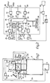
- Number 1 in Fig. 1 indicates, schematically, a motor vehicle internal combustion engine having an intake pipe 2 and an exhaust pipe 3.
- Said intake pipe 2 is fitted inside, in substantially known manner by means of connecting flanges, with an electronic injection unit 4 conveniently consisting of a single-point injector.
- said intake pipe 2 is also fitted with a main throttle 6 having a rotary shaft 7 and the setting of which is controlled mechanically by a pedal-operated accelerator 8.
- the minimum rotation position of said shaft 7 is controlled mechanically by piston 9 of a heat-sensitive element 10 convenient strictlyly containing a wax mixture and, for example, of the type described in Italian Patent Application n.67105-A/87 filed on 17 February, 1987 by the present Applicant, and the content of which is included herein purely by way of reference as required.
- Said heat-sensitive element 10 which is supported on injection unit 4, is thermally connected directly to an electric heating element 14, and is arranged in thermal contact with a circuit 11 for recirculating the engine cooling water and featuring a solenoid valve 12.
- Number 16 indicates an electronic control system mounted on intake pipe 2, for controlling the injection system according to the present invention.
- Said control system 16 is fitted directly with a substantially known type of sensor 17 for detecting the temperature of the air supply to engine 1, and therefore located in such a manner as to be swept by the air flow along pipe 2.
- Control system 16 receives: a first signal 20 from the primary circuit of ignition coil 21, for detecting the speed of engine 1; a second signal 22 (FARF) indicating the setting of throttle 6 and supplied by a conveniently single-track, substantially linear poteniometer 23 connected in known manner to shaft 7; a third signal 24 supplied by a substantially known sensor 25 in exhaust pipe 3, for detecting the concentration of at least one exhaust gas component, and possibly comprising a CO detector in exhaust pipe 3 or even a trivalent catalyst; a fourth signal 26 supplied by a sensor 27 connected to circuit 11, for detecting the temperature of the cooling water of engine 1.
- Control system 16 supplies: a first signal 30 for controlling the single-point injector of unit 4; a second signal 33 for controlling an optical and/or acoustic alarm device 34; a pair of signals 31 (E1) and 32 (E2) for respectively controlling electric heating element 14 and solenoid valve 12.
- Fig.2 shows a more detailed view of control system 16, which comprises a microprocessor-based central processing unit (CPU) 36 connected to RAM and EPROM memory blocks 37 and 38, and fitted directly with an analogue-digital converter block 39 with a relatively small number of inputs (in this case, four).
- CPU central processing unit
- signal 24 supplied by sensor 25 flickers above and below an intermediate range of values defining a substantially correct stoichiometric ratio of the air/fuel mixture being supplied.
- said signal 24 is supplied directly to block 40 of control system 16, which block 40 comprises an amplifying circuit (usually for amplifying signal 24 from 0/1 V to approximately 3 V) followed by a threshold comparator circuit (e.g. a Schmitt trigger).
- Block 40 therefore supplies a digital output signal 41 indicating the concentration of the exhaust gases (rich or lean mixture), and which is sent directly to digital input 42 of central processing unit 36.
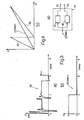
- Signal 22 (FARF) supplied by potentiometer 23 is a linear signal, i.e. the voltage of which is directly proportional to the setting angle ( ⁇ ) of throttle 6, as shown in Fig.4b.
- ⁇ setting angle
- Fig.4b the error percentage of control signal 30 supplied to injection unit 4
- said signal 22 is supplied to block 44 of control system 16 (Fig.2), which supplies output signals 45 and 46 of differing slope, as shown in Fig.4b.
- Said block 44 (Fig.4a) conveniently comprises amplifying blocks 47 and 48, which provide for differing degrees of amplification of input signal 22, and respectively supply output signals 45 and 46, which are supplied respectively to analogue inputs 50 and 51 of analogue-digital converter block 39.
- Central processing unit 36 may supply block 44 with a digital signal 52 for controlling selection of the output signals from block 44, which may present more than two amplifying blocks having different amplifying coefficients, for producing more than two output signals of different slopes and relative to various throttle 6 setting ranges.
- Central processing unit 36 therefore determines the throttle 6 angle ( ⁇ ) as a function of the value of signals 45 and 46.
- Said block 44 is conveniently of the type described in Italian Patent Application entitled “System for converting a signal from a linear transducer, for enabling parameter aquisition to varying degrees of accuracy" filed on the same date by the present Applicant, and the content of which is included herein purely by way of reference as required.
- signals 26 and 54 supplied respectively by sensors 27 and 17 for detecting the cooling water and air supply temperatures of engine 1, are sent to respective inputs of a selecting block 55 of control system 16.
- Block 55 is controlled by a digital signal 56 supplied by processing unit 36, for selecting which signal to supply to the output of block 55 connected to analogue input 58 of analogue-digital converter block 39.
- the speed of engine 1 is indicated by signal 20 on the primary circuit of ignition coil 21. As shown by way of example in Fig. 3a, this presents an initial oscillation of approximately 200V, and a cycle, depending on the speed of engine 1, ranging for example between 5 milliseconds (maximum engine speed) and 45 milliseconds (idling speed).
- Said signal 20 is supplied to block 60 of control system 16, which comprises, for example, a flip-slop supplying a square-wave output signal 61 (SMOT) of approximately 3 milliseconds (Fig.3b), and the frequency of which is therefore a function of the speed of engine 1.
- Said signal 61 is supplied to digital input 62 of central processing unit 36, by which it is processed in the normal manner, e.g. by means of counters, to give the required control parameter.
- the positive system supply voltage from the vehicle battery is supplied, via a switch block 64 controlled by the vehicle ignition key, to analogue input 65 of analogue-digital converter block 39.
- Said switch block 64 also supplies an electric pump 66, for supplying fuel to injection unit 4, via an inertial type relay block 67, i.e. designed to open in the event of the vehicle being arrested sharply, as in the case of collision.
- Central processing unit 36 then supplies signals 30′, 33′, and a pair of signals 31′, 32′, which, via respective pilot blocks 70, 71 and 72, determine control signals 30, 33, and 31, 32.
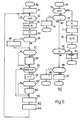
- Fig. 5b shows the signal receiving and sending program of central processing unit 36, which is repeated periodically at convenient intervals of a few milliseconds.
- An "interrupt" starting block 74 goes to block 75, which determines whether engine speed signal 61 (SMOT) is present.
- block 75 goes to block 76, which, in known manner and on the basis of previously received signals 61, calculates parameter N indicating the speed of engine 1.
- Block 76 then goes on to block 77, which enables the single-point injector of injection unit 4, in time with engine 1, and with a predetermined lag in relation to top dead center, determined for example in conventional manner via the vehicle ignition system.
- Block 77 goes on to block 78, which controls acquisition and processing of the signals supplied to inputs 58 and 65 of analogue-digital converter block 39, which marks the end of the subroutine.
- blocks 76, 77 and 78 provide for calculating engine speed parameter N, enabling synchronous injection, alternately picking up the signals from sensors 27 and 17, as well as for picking up the battery voltage signal.
- block 75 goes on to block 80, which determines whether the conditions (as provided for by the main program of processing unit 36) exist for controlling operation of the single-point injector of unit 4.
- block 80 goes on to block 81, which determines signal 30′ for controlling on-off time of the injector either synchronously or asynchronously, as determined by the program, which thus marks the end of the subroutine.
- block 80 determines whether or not the throttle 6 setting signal is to be sampled (sampling is repeated at a predetermined rate, e.g. every 10 milliseconds).
- block 82 goes on to block 83, which controls acquisition and processing of signals 45 and 46 to give the PFARF parameter (and its derivative) indicating the setting ( ⁇ ) of throttle 6.
- Block 83 also controls acquisition of exhaust gas concentration signal 41 supplied by sensor 25, which thus marks the end of the subroutine.
- block 84 determines whether the conditions exist for controlling heat-sensitive element 10.
- block 84 goes on to block 86, which determines signals 31′ and 32′ for controlling electric heating element 14 and solenoid valve 12, e.g. as described in said Italian Patent Application n.67105-A/87, which thus marks the end of the subroutine.
- the main program of processing unit 36 is shown in Fig.5a.
- Starting block 90 goes to block 91, which provides for data and parameter initialization in the various registers and memories.
- Block 91 then goes on to block 92, which determines whether a signal 61 (SMOT) has been supplied to central processing unit 36.
- block 92 In the event of a negative response, block 92 goes back to its input, whereas, in the event of a positive response, it goes on to block 93, which calculates, in known manner, a basic injection time TJ, as a function of the PFARF and N parameters (throttle 6 setting and engine speed) obtained via blocks 83 and 76. Said TJ value is thus determined in open-loop manner.
- Block 93 goes on to block 94, which provides, in substantially known manner, for correcting basic injection time TJ, to give a corrected injection time TJ′.
- Said correction is performed subject to the signals supplied by sensors 21, 17, 27, 23, 25, and the voltage signal at input 65, taken both singly and in conjunction with one another, and subject, for example, to variations in operating parameters, such as the temperature of the cooling water or air supply to engine 1 or supply voltage (which affects delivery by electric pump 66), or to special operating conditions, such as starting of engine 1 or transient engine speeds caused by a sharp change in the setting of throttle 6.
- Block 94 goes on to block 95, which determines, in substantially known manner, the existence of "cut-off" conditions, i.e. release of accelerator pedal 8 with engine 1 running above a predetermined speed threshold.
- block 95 goes on to block 96, which provides for disabling the single-point injector of unit 4 and then goes on to block 97.
- block 97 In the event of a negative response in block 95, this goes directly to block 97.
- Block 97 determines, in substantially known manner as described in said Patent Application n.67105-A/87, whether the conditions exist for controlling engine 1 at idling speed via heat-sensitive element 10. In the event of a positive response, block 97 goes on to block 98, which calculates the values of control signals 31′ and 32′ and then goes on to block 99. In the event of a negative response in block 97, this goes directly to block 99.
- Block 99 determines, in substantially known manner, whether the conditions exist for controlling injection time also as a function of the exhaust gas concentration detected by sensor 25, so as to provide for closed-loop control (such control is not adopted, for example, when warming up engine 1, or at maximum engine power, etc.).
- block 99 goes directly to block 100, and, in the event of a positive response, to block 101, which, in substantially known manner, provides for correcting injection time to give a corrected injection time KTJ′.
- Block 101 then goes on to block 102, which determines, in known manner, the existence of system self-adaptation conditions, due, for example, to variations in input parameters or component values.
- block 102 goes on to block 100, and, in the event of a positive response, to block 103, which provides for calculating the factors by which to correct the set injection plan (N, ⁇ plan).
- Block 103 goes on to block 100, which, in substantially known manner, checks operation of the various input and output circuits on control system 16. In the event of failure, block 100 provides for emitting signal 33′, as well as for controlling the single-point injector of unit 4 in such a manner as to guarantee minimum operation of engine 1.
- Block 100 goes on to block 104 which, depending on the corrected injection time of the single-point injector of unit 4, provides for synchronous or asynchronous injection in relation to the phase of engine 1, and also prepares unit 4 for injection. Block 104 then goes back to block 92.
- the relatively straight-forward circuitry of control system 16 provides for a reliable, relatively low-cost system, with an actual injection time error or no more than a few percent.
- it provides for limiting the number analogue input signals to processing unit 36, so that the analogue-digital converter may even form part of unit 36 itself.
- the engine cooling water and air intake temperature signals are sampled alternately.
- the signal from exhaust gas sensor 25 is supplied directly to a digital input of central processing unit 36.
- Engine air intake temperature sensor 17 is therefore built into control system 16, by virtue of this being mounted in the vicinity of the intake manifold.
- the relative signal is picked up directly from the primary circuit of the ignition coil, thus enabling the signal, by means of a straightforward circuit, to be sent directly to a digital input on central processing unit 36.
- a simple linear potentiometer may be employed for determining the setting of throttle 6, and so obtaining signals of differing slope for different setting ranges, depending on the resolving capacity required.
- operation of the electric fuel supply pump is controlled by means of a straightforward inertial relay.
Landscapes
- Engineering & Computer Science (AREA)
- Chemical & Material Sciences (AREA)
- Combustion & Propulsion (AREA)
- Mechanical Engineering (AREA)
- General Engineering & Computer Science (AREA)
- Electrical Control Of Air Or Fuel Supplied To Internal-Combustion Engine (AREA)
Applications Claiming Priority (2)
| Application Number | Priority Date | Filing Date | Title |
|---|---|---|---|
| IT67081/88A IT1218998B (it) | 1988-02-05 | 1988-02-05 | Sistema di imiezione elettronica di carburante per motori a scoppio |
| IT6708188 | 1988-02-05 |
Publications (2)
| Publication Number | Publication Date |
|---|---|
| EP0327131A2 true EP0327131A2 (de) | 1989-08-09 |
| EP0327131A3 EP0327131A3 (de) | 1989-11-08 |
Family
ID=11299415
Family Applications (1)
| Application Number | Title | Priority Date | Filing Date |
|---|---|---|---|
| EP89102035A Withdrawn EP0327131A3 (de) | 1988-02-05 | 1989-02-06 | Elektronisches Kraftstoffeinspritzsystem für eine Brennkraftmaschine |
Country Status (4)
| Country | Link |
|---|---|
| US (1) | US4986242A (de) |
| EP (1) | EP0327131A3 (de) |
| BR (1) | BR8900549A (de) |
| IT (1) | IT1218998B (de) |
Families Citing this family (8)
| Publication number | Priority date | Publication date | Assignee | Title |
|---|---|---|---|---|
| DE3928709A1 (de) * | 1989-08-30 | 1991-03-07 | Bosch Gmbh Robert | Verfahren und vorrichtung zur ueberpruefung der funktionsfaehigkeit einer abgassondenheizung und deren zuleitungssystem |
| US5086744A (en) * | 1990-01-12 | 1992-02-11 | Mazda Motor Corporation | Fuel control system for internal combustion engine |
| US5704326A (en) * | 1992-12-10 | 1998-01-06 | Hitachi, Ltd. | Air induction system for internal-combustion engine |
| US6032634A (en) * | 1994-11-02 | 2000-03-07 | Hitachi, Ltd. | Air induction system for internal-combustion engine |
| US6412471B1 (en) * | 1999-04-22 | 2002-07-02 | Visteon Global Technologies, Inc. | Throttle body system with integrated electronics |
| JP3596382B2 (ja) | 1999-11-02 | 2004-12-02 | 国産電機株式会社 | 筒内直噴形2サイクル内燃機関用燃料噴射装置及びその制御方法 |
| US7225793B2 (en) * | 2003-08-14 | 2007-06-05 | Electrojet, Inc. | Engine timing control with intake air pressure sensor |
| US6866027B1 (en) | 2003-09-17 | 2005-03-15 | Walbro Engine Management, L.L.C. | Throttle body assembly for a fuel injected combustion engine |
Family Cites Families (19)
| Publication number | Priority date | Publication date | Assignee | Title |
|---|---|---|---|---|
| DE1212781B (de) * | 1962-03-14 | 1966-03-17 | Daimler Benz Ag | Einrichtung zum Abstellen der Brennstoff-foerderung fuer Brennkraftmaschinen, die in Kraftfahrzeugen eingebaut sind |
| CH514780A (de) * | 1970-03-26 | 1971-10-31 | Bosch Gmbh Robert | Anordnung zur elektronischen Gemischdosierung bei Ottomotoren |
| US3996914A (en) * | 1975-06-13 | 1976-12-14 | Chrysler Corporation | Housing for mounting electronic circuit boards on an engine air intake structure |
| JPS597017B2 (ja) * | 1977-05-18 | 1984-02-16 | トヨタ自動車株式会社 | 電子制御燃料噴射式内燃機関 |
| JPS6047460B2 (ja) * | 1977-10-19 | 1985-10-22 | トヨタ自動車株式会社 | 燃料噴射制御装置 |
| JPS55159240A (en) * | 1979-05-31 | 1980-12-11 | Nissan Motor Co Ltd | Collection and control unit of data for automobile |
| JPS562437A (en) * | 1979-06-19 | 1981-01-12 | Nippon Denso Co Ltd | Air-fuel ratio controller |
| JPS56135201A (en) * | 1980-03-24 | 1981-10-22 | Nissan Motor Co Ltd | Pulse generator for engine control |
| US4280465A (en) * | 1980-07-16 | 1981-07-28 | Brunswick Corporation | Throttle control for an electronic fuel-injection control circuit |
| JPS5939942A (ja) * | 1982-08-30 | 1984-03-05 | Toyota Motor Corp | デイ−ゼルエンジンの燃料噴射制御装置 |
| US4543937A (en) * | 1983-03-15 | 1985-10-01 | Toyota Jidosha Kabushiki Kaisha | Method and apparatus for controlling fuel injection rate in internal combustion engine |
| JPS6050250A (ja) * | 1983-08-30 | 1985-03-19 | Toyota Motor Corp | 空燃比制御方法 |
| JPS60138245A (ja) * | 1983-12-26 | 1985-07-22 | Toyota Motor Corp | エンジンの燃料噴射制御装置 |
| JPS60178948A (ja) * | 1984-02-24 | 1985-09-12 | Honda Motor Co Ltd | 内燃エンジンの電子燃料供給制御装置の異常検出表示装置 |
| FR2568631B1 (fr) * | 1984-08-03 | 1987-01-16 | Solex | Carburateur a dispositif de depart automatique |
| IT1188101B (it) * | 1986-04-22 | 1987-12-30 | Weber Spa | Sistema di alloggiamento di una centralina elettronica per un motore endotermico |
| JPS6397843A (ja) * | 1986-10-13 | 1988-04-28 | Nippon Denso Co Ltd | 内燃機関の燃料噴射制御装置 |
| IT1207534B (it) * | 1987-02-17 | 1989-05-25 | Weber Srl | Termico provvisto di alimentazione sistema di controllo del regime di ad iniezione elettronica rotazione minimo di un motore endo |
| US4781267A (en) * | 1987-11-20 | 1988-11-01 | Ford Motor Company | Passive restraint control system |
-
1988
- 1988-02-05 IT IT67081/88A patent/IT1218998B/it active
-
1989
- 1989-02-06 EP EP89102035A patent/EP0327131A3/de not_active Withdrawn
- 1989-02-07 US US07/307,781 patent/US4986242A/en not_active Expired - Fee Related
- 1989-02-08 BR BR898900549A patent/BR8900549A/pt not_active IP Right Cessation
Also Published As
| Publication number | Publication date |
|---|---|
| BR8900549A (pt) | 1989-10-10 |
| EP0327131A3 (de) | 1989-11-08 |
| IT8867081A0 (it) | 1988-02-05 |
| US4986242A (en) | 1991-01-22 |
| IT1218998B (it) | 1990-04-24 |
Similar Documents
| Publication | Publication Date | Title |
|---|---|---|
| US5611311A (en) | Crank angle sensing system | |
| US4403584A (en) | Method and apparatus for optimum control for internal combustion engines | |
| EP0017933B1 (de) | Verfahren und System zum Steuern eines Motors | |
| US5682856A (en) | Apparatus for controlling an internal combustion engine and method thereof | |
| US4321903A (en) | Method of feedback controlling air-fuel ratio | |
| KR920007895B1 (ko) | 엔진 제어용 대기압 검출장치 | |
| US4492202A (en) | Fuel injection control | |
| EP0135176A2 (de) | Motorsteuerungsvorrichtung | |
| JPH033054B2 (de) | ||
| JPH0319900B2 (de) | ||
| JP3170067B2 (ja) | 内燃機関の希薄燃焼制御装置及びこれを備えた燃料噴射量制御装置 | |
| JPS60178944A (ja) | 内燃機関用制御装置 | |
| KR930005157B1 (ko) | 공연비 제어장치 | |
| EP0327131A2 (de) | Elektronisches Kraftstoffeinspritzsystem für eine Brennkraftmaschine | |
| US4805579A (en) | Method of controlling fuel supply during acceleration of an internal combustion engine | |
| EP0163953B1 (de) | Zündzeitpunktregelungsgerät für eine Brennkraftmaschine | |
| US5003956A (en) | Electronic fuel injection control system for a multi-fuel internal combustion engine and method therefore | |
| US5361745A (en) | Combustion state control apparatus for internal combustion engine | |
| US4909223A (en) | Air-fuel ratio control apparatus for multicylinder engine | |
| US4977880A (en) | System for converting a signal from a linear transducer for enabling parameter acquisition to varying degrees of accuracy | |
| US4572122A (en) | Method of controlling internal combustion engine | |
| US5492107A (en) | Air fuel ratio control apparatus for an internal combustion engine | |
| US5035226A (en) | Engine control system | |
| US4951635A (en) | Fuel injection control system for internal combustion engine with compensation of overshooting in monitoring of engine load | |
| US4493300A (en) | Method of controlling the fuel supply to an internal combustion engine at deceleration |
Legal Events
| Date | Code | Title | Description |
|---|---|---|---|
| PUAI | Public reference made under article 153(3) epc to a published international application that has entered the european phase |
Free format text: ORIGINAL CODE: 0009012 |
|
| AK | Designated contracting states |
Kind code of ref document: A2 Designated state(s): DE ES FR GB SE |
|
| PUAL | Search report despatched |
Free format text: ORIGINAL CODE: 0009013 |
|
| AK | Designated contracting states |
Kind code of ref document: A3 Designated state(s): DE ES FR GB SE |
|
| 17P | Request for examination filed |
Effective date: 19900426 |
|
| 17Q | First examination report despatched |
Effective date: 19910125 |
|
| STAA | Information on the status of an ep patent application or granted ep patent |
Free format text: STATUS: THE APPLICATION IS DEEMED TO BE WITHDRAWN |
|
| 18D | Application deemed to be withdrawn |
Effective date: 19910829 |