EP0327143A2 - Epandeur à disques centrifuges - Google Patents
Epandeur à disques centrifuges Download PDFInfo
- Publication number
- EP0327143A2 EP0327143A2 EP89105992A EP89105992A EP0327143A2 EP 0327143 A2 EP0327143 A2 EP 0327143A2 EP 89105992 A EP89105992 A EP 89105992A EP 89105992 A EP89105992 A EP 89105992A EP 0327143 A2 EP0327143 A2 EP 0327143A2
- Authority
- EP
- European Patent Office
- Prior art keywords
- slide
- opening
- centrifugal
- basic
- arrangement
- Prior art date
- Legal status (The legal status is an assumption and is not a legal conclusion. Google has not performed a legal analysis and makes no representation as to the accuracy of the status listed.)
- Withdrawn
Links
Images






Classifications
-
- A—HUMAN NECESSITIES
- A01—AGRICULTURE; FORESTRY; ANIMAL HUSBANDRY; HUNTING; TRAPPING; FISHING
- A01C—PLANTING; SOWING; FERTILISING
- A01C17/00—Fertilisers or seeders with centrifugal wheels
- A01C17/006—Regulating or dosing devices
Definitions
- the invention relates to a centrifugal broadcaster, in particular for granular fertilizers, according to the preamble of patent claim 1.
- the remote control devices each have an operating lever operable from the tractor seat and a Bowden cable producing the connection between the respective slide arrangement and the operating lever.
- Each actuating lever is designed as a toggle lever which is only bringbr in two positions. In one lever position the outlet opening of the associated slide arrangement is closed and in the other position it is fully open.
- the centrifugal spreader according to the invention allows the slide arrangements not only in a closed and in a single open position in which the Outlet openings are completely open, but also to bring them into additional opening positions, so that the application rate varies according to the requirements between a maximum value and the value zero and in this way the centrifugal spreader can be adapted to different operating conditions in the direction of travel.
- the feature according to the invention of setting the slide arrangement to additional open positions makes it possible to realize the potential advantage of the known feature of adjusting the slide arrangements which has not been used hitherto independently of one another. For example, only the interaction of both features allows the centrifugal spreader to be used optimally on a slope.
- the centrifugal spreader according to the invention can be adapted in a simple and quick manner from the tractor seat to all occurring different operating conditions while driving, ie without interrupting the journey.
- each remote control device is advantageously designed with an adjustable marking and / or locking arrangement for fixing the additional opening positions of the slide arrangement.
- the additional opening positions can include a basic opening position and further additional opening positions, the opening widths in the other additional opening positions are larger and smaller than in the basic opening position.
- Each marking and / or locking arrangement preferably comprises at least one marking and / or stop device for fixing the basic opening position and at least two markings and / or stops for fixing two further additional opening positions of the slide arrangement, the opening width of the outlet opening being larger in the two further additional opening positions or is smaller than in the basic opening position.
- Each remote control device can comprise an operating lever connected to the respective slide arrangement via an operating element, with which the markings and / or stops for the two additional additional opening positions interact.
- the operating elements connected to the actuating levers are advantageously designed as Bowden cables.
- the marking and / or stop device for the basic opening position is designed in the form of a marking and / or a stop which interacts with the actuating lever.
- the markings and / or stops for the basic opening position and / or the further additional opening positions can be set independently of one another.
- actuating levers and the markings and / or stops are arranged on a common actuating block which is fastened to a holder which is in the area from which the Slider arrangements are visible, is arranged on the centrifugal spreader.
- the markings and / or stops defining the smallest opening width of the outlet openings are preferably designed such that the actuating levers can be easily moved past these markings and / or stops to the closed position of the slide arrangements.
- the marking and / or stop device for the basic opening position is designed as a latching device, the two interacting latching elements on the slide arrangement and one adjustable and adjustable on the frame of the centrifugal spreader for establishing the basic opening position, interacting with one of the latching elements Locking element includes.
- Each slide arrangement can be designed as a slide-in arrangement with a slide and one of the two locking elements can be fastened to this slide and the other locking element to the locking element.
- each slide arrangement can be designed as a double slide arrangement with a first slide and a second slide, which are adjustable relative to one another and cooperate to determine the opening width of the outlet opening, one of the latching elements being fastened to the first slide and the other latching element to the second slide and the first slide is fixed in the basic opening position by the locking element.
- the double slide arrangement offers the Advantage that the first slides remain in the basic opening position during use and thus determine the basic spreading quantity and only the second slides are adjusted by a comparatively small distance to change the basic spreading quantity. This results in a repeatably very high setting accuracy of the slide arrangements, which is supported by the design of the marking and / or stop device as a latching device.
- the Bowden cable connected to the actuating lever is advantageously connected with its rope to the second slide and is supported by its sleeve on the first slide.
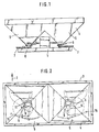
- 1-6 has a frame 1, which is equipped on its front side 3 seen in the direction of travel 2 with coupling elements for attachment to a tractor, not shown.
- a storage container 4 is fastened to the frame 1 and has two funnel-shaped container parts 5 separated by a roof-shaped central part.
- the funnel-shaped container parts 5 have a metering unit 6.
- a distribution member designed as a centrifugal disc 7, the centrifugal discs 7 being driven by the tractor PTO via a gear 8.
- the dosing unit 6 has a base plate 9, which is fastened under the funnel-shaped container parts 5. There is an outlet opening 10 in the base plate 9. Under the base plate 9, a slide 11 is fastened in front of the outlet opening 10 on a bolt 12 welded to the base plate 9. With the help of the slide 11, the outlet opening 10 is to be closed or different opening widths of the outlet opening 10 are to be set. Through the outlet opening 10, the material in the storage container 4, when the slide 11 is in its open position, reaches the centrifugal disks 7, which distribute it in a wide distribution on the floor surface.
- An operating lever 13 projecting beyond the bolt 12 is arranged on the slide 11. Between the base plate 9 and the operating lever 13, a tension spring 14 is attached, which pulls the slide 11 in the direction of the open position. Furthermore, an operating element 15 in the form of a Bowden cable 16 is formed on the slide 11 on the side facing away from the operating lever 13 as part of the remote control device. A separate Bowden cable 16 is separately assigned to each of the sliders 11 arranged under the container parts 5.
- Each Bowden cable has its own operating lever 17 and 18 as part of the remote control device, which are arranged on the operating frame 19 which is to be fastened on the tractor carrying the attachment spreader.
- the handles 20 of the two operating levers 17 and 18 are arranged immediately close to one another, so that the latter can be conveniently adjusted together, so that the two slides 11 are brought into their open or closed positions at the same time.
- Adjustment scales 21 are arranged on the operating frame 19 in addition to the actuation levers 17 and 18, each actuation lever 17 and 18 being assigned its own adjustment scale 21. Furthermore, a locking arrangement is attached to each scale 21 as part of the remote control device in the form of three adjustable pointers or stops 22, 23 and 24. These three adjustable pointers 22, 23 and 24 are each intended for different application quantities of material per unit area.
- the pointers 22 mark the basic application quantity of material per unit area.
- the pointers 23 mark a, for example, 10% smaller application quantity of material per unit area compared to the basic application quantity, and the pointer 24 mark an, for example, 10% larger application quantity of material per unit area compared to the basic application quantity.
- a coupling device 25 is arranged between the actuating levers 17 and 18, via which the two actuating levers 17 and 18 are to be coupled to one another.
- the operating levers 17 and 18 can be moved simultaneously in a simple manner.
- one slide 11 can remain in its closed position while the other slide 11 is brought into its open position. This is of particular importance for border spreading, for example.
- the operating frame 19 is arranged on the tractor.
- the slides 11 are brought into their closed position via the actuating levers 17 and 18, so that they close the outlet opening 10.
- the operating levers 17 and 18 are pushed fully forward so that they point to the 0-marking position of the scales 21 (cf. FIG. 4).
- the pointers 22, 23 and 24 are set on the setting scales 21 on the basis of values taken from the scatter tables.
- the actuating levers 17 and 18 are moved so far at the beginning of the field that they are brought into congruence with the pointers 22. If the application rate is to be reduced or increased during the field crossing, the actuating levers 17 and 18 are set either to the pointer 23 or the pointer 24. In order to be able to set a smaller application rate based on a larger application rate, the slide should be moved a little over the amount to be adjusted in the direction of the closed position and then set to the new adjustment amount value using the actuating levers 17 and 18.
- a friction surface is arranged between the operating frame 19 and the actuating levers 17 and 18 in order to hold the latter in their set position.
- a latching position is provided on the operating frame 19, into which the operating levers 17 and 18 then snap.
- a storage container 104 is fastened to the frame 101 and has two funnel-shaped container parts 105 separated by a roof-shaped central part.
- the funnel-shaped container parts 105 each have a detachable base plate 106, which are fastened to connection elements 107 welded to the container parts 105 with quick-release fasteners 108. These quick-release fasteners are designed as hooks and screws with wing nuts.
- a distribution element designed as a centrifugal disc 109, which is driven by the tractor PTO via a gear 110.
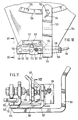
- the base plates 106 are designed as metering elements. There is one in each bottom plate 106 Outlet opening 111, the opening width of which can be adjusted by means of a remote control device, each consisting of a first slide 112 and a second slide 113, arranged below the base plate 106 and in front of the outlet opening 111. Below each base plate 106, the two sliders 112 and 113 are pivotally arranged on a pin 114. The slide 112 is located directly below the base plate 106. The slide 113 is arranged under the slide 112, so that the slide 112 is located between the base plate 106 and the slide 113. An operating lever 115 of the slide 112 protrudes forward over the pin 114.
- a first control element 116 is arranged on this control lever 115, which projects beyond the pin 114, as part of the respective remote control device.
- This control element 116 is designed as a single-acting hydraulic cylinder 117 and as a tension spring 118 counteracting the hydraulic cylinder 117.
- the hydraulic cylinder 117 and the tension spring 118 are fastened to the base plate 106.
- the respective hydraulic cylinder 117 is connected to the hydraulic system of a tractor via a hydraulic hose 119 and can be actuated from there by the tractor driver from the tractor seat via control devices.
- the slide 112 has the extension piece 120 on its side facing away from the operating lever 115.
- This extension piece 120 bears against a stop pin 121 of a locking lever 122, which represents a first element of a latching device that defines a basic opening position of the slide arrangement 112, 113.
- the locking lever 122 is also pivotally mounted on the pin 114.
- the locking lever 122 has an upturned portion 123.
- an adjusting screw 124 is arranged, via which the locking lever 122 can be clamped to a rail 125 welded to the storage container 104, on which there is also an adjusting scale 126.
- the extension piece 120 of the slide 112 bears against the stop bolt 121 of the locking lever 122 when the slide is in its open position.
- the setting scale 126 is provided for the basic setting and has a linear division. On the basis of this setting scale, in conjunction with the values from a spreading chart, the locking lever 122 with stop bolt 121 can be set.
- the slider 113 has an operating lever 127 which extends beyond the extension piece 120 of the slider 112.
- An additional, second control element 128 in the form of a Bowden cable 129, 130 as part of the remote control device is arranged between the control lever 127 of the slide 113 and the extension piece 120 of the slide 112.
- the cable 129 is fastened to the operating lever 127 of the slider 113, while the sleeve 130 of the Bowden cable 128 is screwed onto the extension piece 120 of the slider 112.
- An adjustment scale 131 is arranged on the extension piece 120 of the slide 112. Furthermore, an elongated hole 132 is arranged in the upright piece of the extension piece 120 of the slide 112. A plastic part 133 is fastened to the upright piece of the extension piece 120 of the slide 112 with screws 134. The plastic part 133 also has the elongated hole 132. The slot 132 in the Plastic part 133 has a reduced width in the direction of the center of the elongated hole. In the middle, the elongated hole 132 has on its underside a V-shaped notch 135 as the second element of the locking arrangement determining the basic opening position of the slide arrangement.
- a locking pin 136 is fastened as a third element of the locking device, which protrudes into the elongated hole 132 of the plastic part 133.
- the elongated hole 132 of the plastic part 133 has a height in the region of the locking notch 135 that is smaller than the diameter of the locking bolt 136.
- the plastic part 133 with the elongated hole 132 forms, in connection with the locking pin 136, the locking elements which determine the basic setting of the sliders 112 and 113 to one another when the locking pin 136 is located in the V-shaped locking notch 135.
- the extension piece 127 of the slider 113 has a pointer 137.
- the pointer 137 interacts with the setting scale 131.
- This setting scale 131 has the same division as the scale 126, i.e. if the locking lever 122 is adjusted by one division on the scale 126, this corresponds to the adjustment as if the slide 113 is adjusted by one division relative to the scale 131.
- the actuating lever 138 of the two Bowden cables 128, each Bowden cable of the metering device being assigned to a slinger 109, are arranged on a common actuating block 139.
- Adjustable stops 140 are arranged on the actuating block 139.
- the actuating levers 138 of the Bowden cables come to rest against these stops 140.
- These stops 140 determine the maximum and the minimum Spreading rate of the spreader.
- the stops 140 can be set separately and differently for the two levers 138.
- a holder 141 is attached to the storage container 104, in which the actuating block for setting the maximum and minimum application rate is to be fastened.
- the actuation block 139 is inserted into the holder 141.
- the holder 141 is thus arranged in an area from which the slides 112 and 113 or the scale 131 and the pointer 137 can be viewed.
- the operating block 139 is arranged on the tractor, not shown.
- the actuating block 139 also has markings on which the basic setting and the directions in which the levers have to be moved are indicated if a smaller or a larger application rate is to be set.
- the farmer uses the setting chart to set the locking lever 122 so that the pointer 142 of the locking lever points to the value of the scale 126 taken from the setting table.
- the slides 112 and 113 are in the operating position; ie in the open position. In this position shown by way of example, only a relatively small cross section of the outlet opening 111 released so that a relatively small application rate is applied.
- the operating lever 120 of the slide 112 bears against the stop bolt 121 of the locking lever 122.
- the slides 112 and 113 are actuated via the hydraulic cylinder 117.
- the hydraulic cylinder 117 is depressurized, as in the case shown here, the spring 118 pulls the two slides 112 and 113 into their (shown) open position. If the hydraulic cylinder 117 is now pressurized, the outlet opening is closed by moving the slide into its closed position and covering the outlet opening.
- the extension piece 120 of the slide 112 bears against the stop pin 121.
- the actuating block 139 of the Bowden cables 128 is inserted into the holder 141 on the rear side of the storage container 104.
- the farmer determines how many graduation marks the slide 113 must be adjusted relative to the slide 112 in order to be able to set the maximum and minimum spread rate based on the basic setting.
- the farmer moves the slider 113 in the direction of a larger or smaller spread rate via the respective actuating lever 138 of the respective Bowden cable 128 until the difference in graduation marks is reached; this is set via the scale 131 in connection with the pointer 137.
- this position of the actuating lever 138 is in each case determined by the corresponding adjustable stop 140.
- This type of adjustment of the slide 113 that the setting is read directly on the slide and that the respective slide 113 is always moved by the respective Bowden cable 128 from the same direction to the maximum basic setting, this may have an effect in the Bowden cable and in the connecting parts between the slider 113 and the operating lever not existing game. Rather, it is switched off by this corresponding setting.
- the actuating block is removed from the holder 141 and arranged on the tractor.
- the two slides 113 which are each assigned to a centrifugal disc 109, can be adjusted independently of one another from the tractor seat via the actuating levers 138 of the Bowden cables 128, so that different quantities of application per unit area can be set for each centrifugal disc 109.
- the sliders 113 are moved back and forth relative to the sliders 112 via the Bowden cables 128 in such a way that, starting from the basic setting of the sliders 112 and 113, a larger and a smaller opening cross section of the outlet opening 111 is set with respect to the basic opening width.
- the two slides 113 can each be adjusted independently via the actuating lever 138 of the Bowden cables 128, it is possible, for example, that the maximum application rate per unit area can be set for the right-hand centrifugal disc 109 and the minimum application rate per unit area for the left-hand centrifugal disc. It is also possible that the basic spread rate is set for one centrifugal disc 109 and the maximum or minimum spread rate per unit area is set for the other centrifugal disc 109.
- the locking bolt 136 is located in the V-shaped locking notch 135 according to FIG. 13. Because the elongated hole 132 in the area of the V-shaped locking notch 135 has a smaller height than the diameter of the locking bolt 136 , the locking pin 136 is pressed into the V-shaped notch 135 by the elasticity of the plastic part 133. If the slide 113 is now adjusted relative to the slide 112, the locking pin 136 is pressed out of the V-shaped notch 135 and at the same time, the upper part of the plastic part above the elongated hole 132 is pressed upward, so that the plastic part 133 is elastically deformed, as is shown in FIG. 14.
- the outlet openings 111 are opened at the end of the field in that the hydraulic cylinders 17 are depressurized via the control devices located on the tractor.
- the tension springs 118 suddenly pull the respective sliders 112 and 113 into their set open position, so that the extension piece 120 bears against the stop bolt 121 of the locking lever 122.
- the farmer now wants to spread a slightly smaller or larger spreading quantity during the field crossing and the spreading process due to the prevailing operating conditions, he actuates the corresponding actuating lever 138 of the Bowden cable 128.
- the Bowden cable 128 is then used to move the slide 113 relative to the respective slide 112, so that the adjustment of the actuating lever 138 corresponds to a smaller or a larger opening cross-section compared to the basic setting.
- the opening cross-section of the outlet opening 111 released by the slider 113 can be changed during use of the spreader via the Bowden cable 128 in such a way that a smaller or larger application rate (opening width of the outlet opening) can be set independently of one another for each centrifugal disc 109.
- FIG. 15 shows a left-hand metering unit of an attached centrifugal spreader which, apart from the differences described below, essentially corresponds to the centrifugal spreaders described above.
- Detachable base plates 201 are fastened to container parts (not shown) with the aid of quick-release fasteners.
- a distribution element designed as a centrifugal disc, which is driven by the tractor PTO shaft via a gear.
- the base plates 201 are designed as metering elements.
- each base plate 201 there is an outlet opening 202, the opening width of which can be adjusted by a slide 203 arranged under the base plate 201 in front of the outlet opening 202.
- This slide 203 is pivotable about a pin 204.
- an operating lever 205 projects forward beyond the bolt 204.
- a Bowden cable 207 designed as an operating element 206 is arranged on this operating lever 205.
- the operating lever 205 is connected to a remote control device 208 arranged on a tractor via this Bowden cable 207. This enables the tractor driver to operate the slide 203 from the tractor seat.
- the slide 203 has on its side facing away from the operating lever 205 an extension piece 209 on which an adjustment scale 210 is arranged. Furthermore, an elongated hole guide is arranged in the upright piece of the extension piece 209 of the slide 203.
- a plastic part 211 is fastened to the upright piece of the extension piece 209 of the slide 203 with screws 212.
- the plastic part 211 also has an elongated hole guide 213 with a notch 214 and is designed such that the elongated hole guide 213 is designed to be open in the closing direction of the slide 203.
- the slot guide 213 of the plastic part 211 has a width that decreases in the direction of the center of the slot.
- a locking element 217 protrudes on the lever 216 welded to the adjustable locking element 215.
- the locking element 217 of the adjustable locking element 215 is now in the middle of the slot guide 213 of the slide 203, ie in the V-shaped Notch 214, the slider 203 is in the basic setting set by the locking element 215.
- the pointer 218 arranged on the lever 216 of the adjustable locking element 215 and which cooperates with the setting scale 210 is then also in its basic position.
- the basic setting is carried out via the adjustable locking element 215, which interacts with an adjustment scale arranged on the storage container.
- This setting scale has a linear division.
- the basic setting is made on the basis of this setting scale in connection with the values of a setting chart.
- the setting scale 210 of the slide 203 has the same division as the setting scale arranged on the storage container, ie if the adjustable locking element 215 is adjusted by one division on the container scale, this corresponds to the adjustment as if the slide 203 were adjusted by one Graduation relative to the setting scale 210 is adjusted.
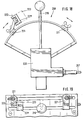
- the stop 221 for the minimum application rate is designed such that it can be easily brought into an inoperative position 223 by pivoting about an axis 222, so that the lever 219 is easily moved past this stop 221 'in order to be able to bring the slide 203 into the closed position .
- the farmer first sets the adjustable locking element 215 using a spreading chart. 18, the slide 203 is in the open position.
- the slide 203 exposes a large cross section of the outlet opening 202, which corresponds to a large application rate.
- the locking element 217 of the locking element 215 is located in the locking notch 214 of the slot guide 213 and shows that the slider 203 is in the basic setting.
- the actuating block 220 of the Bowden cables 207 is inserted into a holder on the rear of the storage container.
- the farmer determines by how many graduations of the setting scale 210 the slide 203 has to be adjusted in order to be able to set the maximum and the minimum application rate based on the basic setting.
- the farmer moves the slider 203 in the direction of larger or smaller spreading quantities via the respective actuating lever 219 of the respective Bowden cable 207 until the difference in graduation marks is reached. This is set via the scale 210 in connection with the pointer 218.
- this position of the actuating lever 219 is in each case determined by a correspondingly adjustable stop 221.
- the actuating block 220 is removed from the holder of the rear container wall and arranged on the tractor.
- the locking element 217 engages in the V-shaped notch 214, which can be felt noticeably when the respective actuating lever 219 is moved, the respective slide 203 can be safely reset to the basic setting.
- the respective actuating levers 219 of the Bowden cables 207 can be used to adjust the slides 203 independently of one another from the tractor seat, so that differently large application rates per unit area can be set for each centrifugal disc. Because the respective slider 203 can be adjusted independently via the actuating lever 219 of the Bowden cables 207, it is possible, for example, that the maximum spread rate per unit area can be set for the right-hand centrifugal disc and the minimum spread rate per unit area for the left-hand centrifugal disc. It is also possible to set the basic spread rate for one centrifugal disc and to set the maximum or minimum spread rate per unit area for the other centrifugal disc.
- the respective slide 203 is also in the basic setting when the locking element 217, which is arranged on the small lever 216 of the adjustable locking element 215, is in the V-shaped locking notch 214 the slot guide 213 of the extension piece 209 arranged on the slide 203 is located.
- the elongated hole guide 213 in the region of the V-shaped notch 214 has a smaller height than the diameter of the latching bolt designed as a latching element 217, the latching element 217 is pressed into the V-shaped notch 214 by the elasticity of the plastic part 211.
- the locking element 217 is pressed out of the V-shaped notch 214 and at the same time the lower part of the plastic part is pressed down below the elongated hole guide 213, so that the plastic part 211 is elastically deformed.
- the outlet openings 202 are opened by actuating the actuating levers 219 of the actuating block 220.
- the slider 203 is adjusted by the Bowden cable 207 arranged on the operating lever 205 of the slider 203.
- the actuating lever 219 is moved in the opening direction of the slider 203 until the latching element 217 of the adjustable element 215 in the V- Shaped notch 214 engages, which can be felt noticeably when moving the respective operating lever 219.
- the slide 203 is in the basic setting set with the aid of the adjustable locking element 215.
- the farmer now wants to spread a slightly smaller or larger spreading quantity during the field crossing and the spreading process due to the prevailing operating conditions, he actuates the corresponding actuating lever 219 of the Bowden cable 207.
- the respective slide 203 is then moved via this Bowden cable 207, so that the Adjustment of the actuating lever 219 a smaller or a larger opening cross-section is set compared to the basic setting. If the basic spreading quantity is then to be applied again, the farmer moves the corresponding actuating lever 219 back until he noticeably notices on the actuating lever that the latching element 217 engages in the V-shaped notch 214 of the elongated hole guide 213 of the slide 203.
- the farmer must bring the stop 221 'indicating the minimum application quantity into the inoperative position 223, so that the slider 203 can be brought into its closed position when the actuating lever 219 is actuated via the Bowden cable 207. If the slide 203 is now returned to its open position with the aid of the actuating lever 219, the stop 221 indicating the minimum application quantity must be pivoted back again, so that the actuating lever 219 comes to rest against this stop 221 when the minimum application quantity is set.
- the opening cross-section of the outlet opening 202 released by the slide 203 can be changed during use of the spreader via the Bowden cable 207 as part of the remote control device 208 in such a way that a smaller or larger application rate can be set independently for each centrifugal disc. It is thus achieved in the simplest way that the setting of differently large opening widths of the outlet opening 202 or the closing of this outlet opening is achieved with the aid of only one slide 203 per metering element.
- FIG. 20 also shows a base plate 201, the setting of the different application rates being about a setting device deviating from the previous exemplary embodiment takes place.
- the base plate 201 there is also an outlet opening 202, the opening width of which can be adjusted by a slide 224 arranged below and in front of the outlet opening 202.
- This slide 224 is pivotable about a pin 225 and has an extension piece 226 on its side facing away from the pin 225, to which the Bowden cable 207 is articulated. Via this Bowden cable 207, the slide 224 is connected to the remote control device 208 arranged on a tractor, so that the slide 224 can be adjusted from the tractor seat.
- the base plate 201 has an adjustment scale 227 at its rear end, which has a linear division.
- an elongated hole 228 In front of the setting scale 227 there is an elongated hole 228 in which an adjustable locking element 229 is guided and can be fixed with screws 230.
- This adjustable locking element 229 has a pointer 231 which interacts with the setting scale 227.
- the adjustable locking element 229 is designed as a plastic part 232 and has an elongated hole guide 233 with a V-shaped notch 234.
- the elongated hole guide 233 is designed to be open in the closing direction of the slide 224, so that the slide 224 can engage in this elongated hole guide 233 and can also be returned to its closed position, the slide 224 having a catch 235 which engages with the notch 234 of the adjustable locking element 229 interacts (see Fig. 21).
- the locking element 229 with the elongated hole guide 223 is designed such that the elongated hole 236 in the region of the locking notch 234 Has height that is smaller than the height of the parts of the slider 224 engaging in the elongated hole 236.
- the setting of the application rate is carried out via the actuating lever 219 on the actuating block 220.
- the catch 235 of the slide 224 is located in the notch 234 of the adjustable locking element 229.
- the respective actuating lever 219 of the remote control device 208 which can be arranged on the rear wall of the container to adjust the application rate, is moved until the pointer 231 of the adjustable locking element 229, which now interacts with the slide 224, displays the desired value, which can be read on the setting scale 227 of the base plate 201.
- This value represents the basic application quantity value. Starting from this basic application quantity value, the respective minimum and maximum application quantity values are determined, these respective application quantity values being set by the adjustable stops 221 on the remote control element 208.
- the actuating lever 219 comes to rest against these stops 221 when the minimum or maximum application rate is to be set in each case.
- the pointer 231 of the adjustable locking element 229 is reset to the basic application quantity value by actuating the lever 219 via the Bowden cable 207, and the adjustable locking element 229 is clamped in this position with the screws 230 on the base plate 201.
- the spreading of the material can be started, as already described, wherein different application rates can be set by changing the opening width of the outlet openings 202 and the outlet opening can also be adjusted with this slide 224 using only one slide 224 can be closed in the simplest way.
- FIG. 22 shows a further actuation block 220 which has a stop 237 which determines the minimum application rate and has two inclined surfaces 238, by means of which the actuation levers 219 can be easily moved away.
- the levers 219 each have yielding elements 239 which can deflect against the spring force of the spring 240, as a result of which the actuating lever 219 can be lifted over this stop 237 to close the slide of a base plate 106.
- the element 239 assumes the position shown in broken lines.
- an adjustment scale can be arranged on the actuation block 220, so that the basic adjustment is also possible from the tractor before the spreading work begins. Furthermore, it can be provided according to the invention that on the actuating block 220 or on the scale between the two stops 221 and 237, a third stop 241 shown with dash-dotted lines is adjustably arranged. This stop 241 indicates the normal spread rate. The element 239 can also slide over this stop 241 by lifting so that the actuating lever 219 can be moved past this stop. The stops 237, 241 and 221 thus mark or determine the minimum application rate, the normal application rate and the maximum application rate.
Landscapes
- Life Sciences & Earth Sciences (AREA)
- Soil Sciences (AREA)
- Environmental Sciences (AREA)
- Fertilizing (AREA)
Priority Applications (1)
| Application Number | Priority Date | Filing Date | Title |
|---|---|---|---|
| EP19890105992 EP0327143A3 (fr) | 1985-02-06 | 1986-02-06 | Epandeur à disques centrifuges |
Applications Claiming Priority (7)
| Application Number | Priority Date | Filing Date | Title |
|---|---|---|---|
| DE3503907 | 1985-02-06 | ||
| DE19853503907 DE3503907A1 (de) | 1985-02-06 | 1985-02-06 | An einem schlepper angebauter anbauschleuderstreuer |
| DE19853533217 DE3533217A1 (de) | 1985-09-18 | 1985-09-18 | Anbauschleuderstreuer, insbesondere fuer gekoernte duengemittel |
| DE3533217 | 1985-09-18 | ||
| DE3540784 | 1985-11-16 | ||
| DE19853540784 DE3540784A1 (de) | 1985-11-16 | 1985-11-16 | Anbauschleuderstreuer, insbesondere fuer gekoernte duengemittel |
| EP19890105992 EP0327143A3 (fr) | 1985-02-06 | 1986-02-06 | Epandeur à disques centrifuges |
Related Parent Applications (2)
| Application Number | Title | Priority Date | Filing Date |
|---|---|---|---|
| EP86101534.5 Division | 1986-02-06 | ||
| EP86101534A Division EP0191417B1 (fr) | 1985-02-06 | 1986-02-06 | Epandeur centrifuge, en particulier pour engrais granulé |
Publications (2)
| Publication Number | Publication Date |
|---|---|
| EP0327143A2 true EP0327143A2 (fr) | 1989-08-09 |
| EP0327143A3 EP0327143A3 (fr) | 1991-10-23 |
Family
ID=27433290
Family Applications (1)
| Application Number | Title | Priority Date | Filing Date |
|---|---|---|---|
| EP19890105992 Withdrawn EP0327143A3 (fr) | 1985-02-06 | 1986-02-06 | Epandeur à disques centrifuges |
Country Status (1)
| Country | Link |
|---|---|
| EP (1) | EP0327143A3 (fr) |
Cited By (1)
| Publication number | Priority date | Publication date | Assignee | Title |
|---|---|---|---|---|
| IT202200019029A1 (it) * | 2022-09-16 | 2024-03-16 | Dal Cero Metalworking Di Dal Cero Sergio & Diego S N C | Macchina agricola per distribuire prodotti di trattamento sul terreno |
Family Cites Families (4)
| Publication number | Priority date | Publication date | Assignee | Title |
|---|---|---|---|---|
| US2843387A (en) * | 1955-06-22 | 1958-07-15 | Cyclone Seeder Co | Broadcast seeder or spreader device |
| GB1042440A (en) * | 1962-09-25 | 1966-09-14 | Lely Nv C Van Der | Improvements in or relating to implements for distributing granular or powdery material |
| NL7609902A (nl) * | 1976-09-07 | 1978-03-09 | Lely Nv C Van Der | Inrichting voor het verspreiden van korrel- en/of poedervormig materiaal. |
| FR2412247A1 (fr) * | 1977-12-24 | 1979-07-20 | Amazonen Werke Dreyer H | Distributeur centrifuge, notamment pour engrais |
-
1986
- 1986-02-06 EP EP19890105992 patent/EP0327143A3/fr not_active Withdrawn
Cited By (2)
| Publication number | Priority date | Publication date | Assignee | Title |
|---|---|---|---|---|
| IT202200019029A1 (it) * | 2022-09-16 | 2024-03-16 | Dal Cero Metalworking Di Dal Cero Sergio & Diego S N C | Macchina agricola per distribuire prodotti di trattamento sul terreno |
| EP4338564A1 (fr) | 2022-09-16 | 2024-03-20 | Dal Cero Metalworking S.n.c. di Dal Cero Sergio & Diego | Machine agricole pour distribuer des produits de traitement sur le sol |
Also Published As
| Publication number | Publication date |
|---|---|
| EP0327143A3 (fr) | 1991-10-23 |
Similar Documents
| Publication | Publication Date | Title |
|---|---|---|
| EP0495237B1 (fr) | Méthode de réglage des doseurs d'un distributeur | |
| EP0758727A2 (fr) | Transmission hydrostatique pour un véhicule avec un levier de commande | |
| DE3641080C2 (de) | Schleuderdüngerstreuer | |
| EP0192089B1 (fr) | Distributeur à disques, spécialement pour engrais en granulés | |
| EP0337069B1 (fr) | Distributeur à disques | |
| DE2659523C2 (de) | Sämaschine | |
| EP0327143A2 (fr) | Epandeur à disques centrifuges | |
| EP0191417B1 (fr) | Epandeur centrifuge, en particulier pour engrais granulé | |
| EP0327137B1 (fr) | Distributeur centrifuge | |
| DE4106560A1 (de) | Schleuderduengerstreuer | |
| DE69117817T2 (de) | Gerät zur Dosierung von Material | |
| DE3503908A1 (de) | Anbauschleuderstreuer, insbesondere fuer gekoernte duengemittel | |
| DE3503905A1 (de) | Anbauschleuderstreuer, insbesondere fuer gekoernte duengemittel | |
| DE2747589C2 (de) | Vorrichtung zum Anzeigen von Symbolen an Schalthebeln | |
| DE3609528A1 (de) | An einen schlepper anzubauender anbauschleuderstreuer | |
| DE4222701A1 (de) | Elektronische Anzeigevorrichtung für einen Zentrifugalstreuer | |
| EP0613613A1 (fr) | Epandeur centrifuge | |
| DE3540784A1 (de) | Anbauschleuderstreuer, insbesondere fuer gekoernte duengemittel | |
| DE2628798B2 (de) | Anbauvorrichtung für Schleuderdüngerstreuer | |
| DE3533217A1 (de) | Anbauschleuderstreuer, insbesondere fuer gekoernte duengemittel | |
| DE2658451A1 (de) | Vorrichtung zur fluessigkeitsmengensteuerung bei feldspritzen | |
| DE3535629A1 (de) | Schleuderstreuer, insbesondere fuer gekoernte duengemittel | |
| DE3632285C2 (fr) | ||
| DE3503907A1 (de) | An einem schlepper angebauter anbauschleuderstreuer | |
| DE8703454U1 (de) | An einen Schlepper anzubauender Anbauschleuderstreuer |
Legal Events
| Date | Code | Title | Description |
|---|---|---|---|
| PUAI | Public reference made under article 153(3) epc to a published international application that has entered the european phase |
Free format text: ORIGINAL CODE: 0009012 |
|
| 17P | Request for examination filed |
Effective date: 19890405 |
|
| AC | Divisional application: reference to earlier application |
Ref document number: 191417 Country of ref document: EP |
|
| AK | Designated contracting states |
Kind code of ref document: A2 Designated state(s): AT BE CH DE FR GB IT LI LU NL SE |
|
| PUAL | Search report despatched |
Free format text: ORIGINAL CODE: 0009013 |
|
| AK | Designated contracting states |
Kind code of ref document: A3 Designated state(s): AT BE CH DE FR GB IT LI LU NL SE |
|
| 17Q | First examination report despatched |
Effective date: 19921208 |
|
| STAA | Information on the status of an ep patent application or granted ep patent |
Free format text: STATUS: THE APPLICATION IS DEEMED TO BE WITHDRAWN |
|
| 18D | Application deemed to be withdrawn |
Effective date: 19940715 |