EP0327218A2 - Hydraulische Antiblockier-Bremssysteme - Google Patents
Hydraulische Antiblockier-Bremssysteme Download PDFInfo
- Publication number
- EP0327218A2 EP0327218A2 EP89300426A EP89300426A EP0327218A2 EP 0327218 A2 EP0327218 A2 EP 0327218A2 EP 89300426 A EP89300426 A EP 89300426A EP 89300426 A EP89300426 A EP 89300426A EP 0327218 A2 EP0327218 A2 EP 0327218A2
- Authority
- EP
- European Patent Office
- Prior art keywords
- brake
- valve
- pump
- master cylinder
- plunger
- Prior art date
- Legal status (The legal status is an assumption and is not a legal conclusion. Google has not performed a legal analysis and makes no representation as to the accuracy of the status listed.)
- Ceased
Links
Images


Classifications
-
- B—PERFORMING OPERATIONS; TRANSPORTING
- B60—VEHICLES IN GENERAL
- B60T—VEHICLE BRAKE CONTROL SYSTEMS OR PARTS THEREOF; BRAKE CONTROL SYSTEMS OR PARTS THEREOF, IN GENERAL; ARRANGEMENT OF BRAKING ELEMENTS ON VEHICLES IN GENERAL; PORTABLE DEVICES FOR PREVENTING UNWANTED MOVEMENT OF VEHICLES; VEHICLE MODIFICATIONS TO FACILITATE COOLING OF BRAKES
- B60T8/00—Arrangements for adjusting wheel-braking force to meet varying vehicular or ground-surface conditions, e.g. limiting or varying distribution of braking force
- B60T8/32—Arrangements for adjusting wheel-braking force to meet varying vehicular or ground-surface conditions, e.g. limiting or varying distribution of braking force responsive to a speed condition, e.g. acceleration or deceleration
- B60T8/34—Arrangements for adjusting wheel-braking force to meet varying vehicular or ground-surface conditions, e.g. limiting or varying distribution of braking force responsive to a speed condition, e.g. acceleration or deceleration having a fluid pressure regulator responsive to a speed condition
- B60T8/50—Arrangements for adjusting wheel-braking force to meet varying vehicular or ground-surface conditions, e.g. limiting or varying distribution of braking force responsive to a speed condition, e.g. acceleration or deceleration having a fluid pressure regulator responsive to a speed condition having means for controlling the rate at which pressure is reapplied to or released from the brake
- B60T8/5012—Pressure reapplication using a plurality of valves in parallel
-
- B—PERFORMING OPERATIONS; TRANSPORTING
- B60—VEHICLES IN GENERAL
- B60T—VEHICLE BRAKE CONTROL SYSTEMS OR PARTS THEREOF; BRAKE CONTROL SYSTEMS OR PARTS THEREOF, IN GENERAL; ARRANGEMENT OF BRAKING ELEMENTS ON VEHICLES IN GENERAL; PORTABLE DEVICES FOR PREVENTING UNWANTED MOVEMENT OF VEHICLES; VEHICLE MODIFICATIONS TO FACILITATE COOLING OF BRAKES
- B60T8/00—Arrangements for adjusting wheel-braking force to meet varying vehicular or ground-surface conditions, e.g. limiting or varying distribution of braking force
- B60T8/32—Arrangements for adjusting wheel-braking force to meet varying vehicular or ground-surface conditions, e.g. limiting or varying distribution of braking force responsive to a speed condition, e.g. acceleration or deceleration
- B60T8/34—Arrangements for adjusting wheel-braking force to meet varying vehicular or ground-surface conditions, e.g. limiting or varying distribution of braking force responsive to a speed condition, e.g. acceleration or deceleration having a fluid pressure regulator responsive to a speed condition
- B60T8/42—Arrangements for adjusting wheel-braking force to meet varying vehicular or ground-surface conditions, e.g. limiting or varying distribution of braking force responsive to a speed condition, e.g. acceleration or deceleration having a fluid pressure regulator responsive to a speed condition having expanding chambers for controlling pressure, i.e. closed systems
- B60T8/4275—Pump-back systems
- B60T8/4283—Pump-back systems having a pressure sensitive inlet valve
-
- B—PERFORMING OPERATIONS; TRANSPORTING
- B60—VEHICLES IN GENERAL
- B60T—VEHICLE BRAKE CONTROL SYSTEMS OR PARTS THEREOF; BRAKE CONTROL SYSTEMS OR PARTS THEREOF, IN GENERAL; ARRANGEMENT OF BRAKING ELEMENTS ON VEHICLES IN GENERAL; PORTABLE DEVICES FOR PREVENTING UNWANTED MOVEMENT OF VEHICLES; VEHICLE MODIFICATIONS TO FACILITATE COOLING OF BRAKES
- B60T8/00—Arrangements for adjusting wheel-braking force to meet varying vehicular or ground-surface conditions, e.g. limiting or varying distribution of braking force
- B60T8/32—Arrangements for adjusting wheel-braking force to meet varying vehicular or ground-surface conditions, e.g. limiting or varying distribution of braking force responsive to a speed condition, e.g. acceleration or deceleration
- B60T8/34—Arrangements for adjusting wheel-braking force to meet varying vehicular or ground-surface conditions, e.g. limiting or varying distribution of braking force responsive to a speed condition, e.g. acceleration or deceleration having a fluid pressure regulator responsive to a speed condition
- B60T8/42—Arrangements for adjusting wheel-braking force to meet varying vehicular or ground-surface conditions, e.g. limiting or varying distribution of braking force responsive to a speed condition, e.g. acceleration or deceleration having a fluid pressure regulator responsive to a speed condition having expanding chambers for controlling pressure, i.e. closed systems
- B60T8/4275—Pump-back systems
- B60T8/4291—Pump-back systems having means to reduce or eliminate pedal kick-back
-
- B—PERFORMING OPERATIONS; TRANSPORTING
- B60—VEHICLES IN GENERAL
- B60T—VEHICLE BRAKE CONTROL SYSTEMS OR PARTS THEREOF; BRAKE CONTROL SYSTEMS OR PARTS THEREOF, IN GENERAL; ARRANGEMENT OF BRAKING ELEMENTS ON VEHICLES IN GENERAL; PORTABLE DEVICES FOR PREVENTING UNWANTED MOVEMENT OF VEHICLES; VEHICLE MODIFICATIONS TO FACILITATE COOLING OF BRAKES
- B60T8/00—Arrangements for adjusting wheel-braking force to meet varying vehicular or ground-surface conditions, e.g. limiting or varying distribution of braking force
- B60T8/32—Arrangements for adjusting wheel-braking force to meet varying vehicular or ground-surface conditions, e.g. limiting or varying distribution of braking force responsive to a speed condition, e.g. acceleration or deceleration
- B60T8/34—Arrangements for adjusting wheel-braking force to meet varying vehicular or ground-surface conditions, e.g. limiting or varying distribution of braking force responsive to a speed condition, e.g. acceleration or deceleration having a fluid pressure regulator responsive to a speed condition
- B60T8/50—Arrangements for adjusting wheel-braking force to meet varying vehicular or ground-surface conditions, e.g. limiting or varying distribution of braking force responsive to a speed condition, e.g. acceleration or deceleration having a fluid pressure regulator responsive to a speed condition having means for controlling the rate at which pressure is reapplied to or released from the brake
- B60T8/5006—Pressure reapplication by pulsing of valves
-
- B—PERFORMING OPERATIONS; TRANSPORTING
- B60—VEHICLES IN GENERAL
- B60T—VEHICLE BRAKE CONTROL SYSTEMS OR PARTS THEREOF; BRAKE CONTROL SYSTEMS OR PARTS THEREOF, IN GENERAL; ARRANGEMENT OF BRAKING ELEMENTS ON VEHICLES IN GENERAL; PORTABLE DEVICES FOR PREVENTING UNWANTED MOVEMENT OF VEHICLES; VEHICLE MODIFICATIONS TO FACILITATE COOLING OF BRAKES
- B60T8/00—Arrangements for adjusting wheel-braking force to meet varying vehicular or ground-surface conditions, e.g. limiting or varying distribution of braking force
- B60T8/32—Arrangements for adjusting wheel-braking force to meet varying vehicular or ground-surface conditions, e.g. limiting or varying distribution of braking force responsive to a speed condition, e.g. acceleration or deceleration
- B60T8/34—Arrangements for adjusting wheel-braking force to meet varying vehicular or ground-surface conditions, e.g. limiting or varying distribution of braking force responsive to a speed condition, e.g. acceleration or deceleration having a fluid pressure regulator responsive to a speed condition
- B60T8/50—Arrangements for adjusting wheel-braking force to meet varying vehicular or ground-surface conditions, e.g. limiting or varying distribution of braking force responsive to a speed condition, e.g. acceleration or deceleration having a fluid pressure regulator responsive to a speed condition having means for controlling the rate at which pressure is reapplied to or released from the brake
- B60T8/5018—Pressure reapplication using restrictions
- B60T8/5025—Pressure reapplication using restrictions in hydraulic brake systems
- B60T8/5037—Pressure reapplication using restrictions in hydraulic brake systems closed systems
Definitions
- This invention relates to hydraulic anti-lock braking systems for vehicles of the kind in which the supply of hydraulic fluid from a supply, suitably a master cylinder, to a brake on a wheel is modulated in an anti-lock mode in accordance with the behaviour of the braked wheel, and a pump is adapted to generate the energy necessary to re-apply the brake automatically after the pressure applied to the brake has first been released to prevent the wheel from locking.
- a first control valve is adapted to isolate the master cylinder from the brake, and a second control valve is adapted to release fluid from the brake to an expansion chamber.
- the pump which is driven by an electric motor, is adapted to return fluid from the expansion chamber to the master cylinder, and the first valve is also used to control the rate at which the brake is re-applied.
- the pump which is driven by a motor is adapted to pump fluid back both to the brake and to the master cylinder during an anti-lock mode.
- substantially 70% of output from the pump is returned to the brake, and the remaining substantially 30% is returned to the master cylinder.
- the pump comprises a plunger working in a bore in a housing and movable in a first direction during an induction stroke to draw fluid into a pressure space in the bore in front of the plunger from an expansion chamber and through a one-way inlet valve, the plunger being movable in a second opposite direction during a power stroke to pump fluid from the pressure space to the brake and to the master cylinder through respective first and second flow-control means.
- the flow-control means are so constructed and arranged that a major portion of the output from the pump is returned to the brake during the delivery stroke of the pump and a relatively smaller portion is returned to the master cylinder.
- the first flow-control means may comprise a restricted orifice or a first one-way outlet valve
- the second flow-control means may comprise a second one-way outlet valve
- the first flow-control means comprises a first one-way outlet valve
- one of the outlet valves is rendered inoperative when the plunger has moved through a first predetermined distance during the power stroke whereafter the output from the pump during the reminder of the power stroke takes place through the other one-way valve.
- the outlet valves may be arranged so that fluid is pumped to the brake during movement of the plunger through the first predetermined distance, with the output from the pump during the remainder of the power stroke being pumped to the master cylinder after an output port leading to the one-way valve through which the brake is supplied has been masked by the plunger.
- the orifice When the first flow-control valve comprises the restricted orifice, the orifice is so positioned, constructed, and arranged that it achieves a build up of back pressure capable of causing the second one-way valve to open. This allows partial feedback of fluid to the master cylinder, at the same time as fluid is pumped back to the brake.
- a first normally-open control valve is located between the master cylinder and the brake
- a second normally-closed control valve is located between the brake and the expansion chamber, both control valves being responsive to an anti-lock signal whereby the first valve to caused to close and isolate the master cylinder from the brake, the second valve is caused to open to release fluid from the brake to the expansion chamber, and the motor is operated to cause the pump plunger to oscillate.
- Both control valves may comprise solenoid-operated valves.
- the first valve may comprise a flow-regulator.
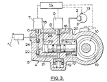
- fluid under pressure from a master cylinder 1 is applied to a brake 2 or a wheel 3 of a vehicle through a modulator assembly 4.
- the modulator assembly 4 comprises a housing 5 incorporating a first valve 6 controlled by a first solenoid 7, a second valve 8 controlled by a second solenoid 9, an hydraulic pump 10 driven by an electric motor 11, and an expansion chamber 12 of which the effective volume is variable.
- Signals from a sensor 13 sensing the behaviour of the wheel 3 are fed to an electronic control module 14 which controls energisation of the two solenoids 7 and 9 and operation of the electric motor 11.
- the first valve 6 controls communication from the master cylinder 1 to the brake 2 through a passage 15 in the housing 5, and the second valve 8 controls communication between the passage 15, and transverse passage 16 leading to the expansion chamber 12.
- the pump 10 comprises a plunger 17 which is reciprocable in a bore 18 by means of an eccentric drive 19 from the motor 11, and a spring 20 acts to hold the plunger 17 in engagement with the drive 19.
- a pressure space 21 is defined in the bore 18 in advance of the plunger 17.
- fluid is drawn into the pressure space 21 from the expansion chamber 12 through a one-way inlet valve 22.
- fluid is pumped from the pressure space through first and second one-way outlet valves 23 and 24.
- the first outlet valve 23 leads from the pressure space 21 to the passage 15 on the downstream side of the valve 24, and is located in the wall of the bore 18 at a position spaced from the inner end of the plunger 17, at least when the plunger 17 is in a retracted position at the extent of its induction stroke.
- the second outlet valve 24 is disposed between the end of the bore 18 and the master cylinder 1.
- valve 6 In a normal inoperative "brakes-off" position the valve 6 is open to provide unrestricted communication between the master cylinder 1 and the brake 2, the valve 8 is closed to isolate the brake 2 from the expansion chamber 12, and the motor 11 is stationary.
- control module 14 When the control module 14 receives a skid signal from the sensor 13 indicative of a critical wheel condition, the module 14 is operative to energise the solenoids 7 and 9 to close the valve 6 and open the valve 8, and to energise the motor 11 to cause the plunger 17 to reciprocate in the bore 18.
- the corresponding signal from the sensor 13 causes the control module 14 to permit the valve 8 to close.
- the pump 10 pumps fluid from the expansion chamber 12 to the brake 2 and to the master cylinder 1 but, since the valve 8 has closed, the chamber 12 is not replenished from the brake 2 because communication through the passage 16 has been cut-off.
- the brake 2 is therefore re-applied by the pump 10, until the fluid within the expander chamber 12 has been recovered.
- the pressure applied to the brake 2 is held at a level below that which caused the skid signal, at least for a predetermined period of time. This period is related to the behaviour of the wheel 3 immediately prior to the skid signal.
- the brake pressure will be re-applied to almost the pressure applied when the skid signal was emitted.
- the solenoid 7 will be pulsed to increase the pressure further by allowing the higher pressure at the master cylinder 1 to be applied to the brake 2.
- the brake pressure will be applied to a lower level and will be retained at that level for a relatively longer period before the solenoid 7 is pulsed to increase the pressure further.
- Figure 2 shows a trace of brake pressure (P) plotted against time (t) for the characteristics of the system of Figure 1 and which illustrates the following actions:
- the pedal will be eased down to increase brake pressure. Normally, therefore, the brake pedal will move to a position to apply the brakes and in anti-lock mode, will only move slightly, in both directions, from this position.
- This enables us to use as the tandem master cylinder 1 a master cylinder of the standard AS/AS type.
- a recuperation seal on each piston is adapted to close a radial recuperation port in the wall of the body of the master cylinder. Any movement of the pistons, which dictates the pedal movement described in stage (4-5), will be insufficient to cause any damage to the recuperation seals, in comparison with other known anti-lock systems, for example of the kind in which the total output from a pump is returned to the master cylinder.
- the orifice 28 is adapted to achieve a build up of back pressure in the pressure space 21 which is capable of temporarily causing the valve 24 to open. This allows partial feedback of fluid to the master cylinder 1 at the same time as fluid is pumped to the brake 2 through the orifice 28.
- the brake 2 comprises a brake on one front wheel 3 of a four-wheel vehicle, and the modulator assembly 4 is adapted also to control the behaviour of a brake 30 on the diagonally opposite rear wheel 31.
- the master cylinder 1 is connected to the rear wheel brake 30 through a passage 32 in the housing 5, and the modulator assembly 4 incorporates a third valve 33 controlled by a third solenoid 34, and a fourth valve 35 controlled by a fourth solenoid 36.
- the third valve 33 controls communication from the master cylinder 14 to the brake 30 through the passage 32 and the fourth valve 35 controls communication between the passage 32, and a passage 37 leading to the expansion chamber 12 through the passage on the upstream side of the one-way valve 22.
- Signals from a sensor 38 sensing the behaviour of the rear wheel 31 are fed to the control module 14 which also controls energisation of the two solenoids 34 and 36.
- Operation of the front wheel brake 2 is controlled during normal braking and during an anti-lock mode as described above with reference to Figures 1 and 2.
- the front wheel brake 2 is applied as described above with reference to Figures 1 and 2.
- the valve 33 is open and the valve 35 is closed so that fluid is also supplied to the rear wheel brake 31 from the master cylinder 1 and through the passage 32.
- control module 14 is operative to energise the solenoids 34 and 36 to close the valve 33 and open the valve 35, and to energise the motor 11 to cause the plunger 17 to reciprocate in the bore 18.
- the corresponding signal from the sensor 38 causes the control module 14 to permit the valve 36 to close.
- the pump 10 pumps fluid from the expansion chamber 12 to the master cylinder 1, but since the valve 36 has closed, the chamber 12 is not replenished from the brake 30.
- the solenoid 34 will be pulsed which allows the higher pressure at the master cylinder 1 to be applied to the brake 30.
- the fluid relieved from the rear brake 31 during its anti-lock mode is relieved to the same expansion chamber 12 as that to which the fluid from the front wheel brake 2 is relieved and the pump 10 is arranged to increase output to the master cylinder 1 to compensate for the volume requirements of the rear brake 31.
- the third valve 33 will close and the first valve 6 will open to prevent the front wheel from spinning.
- the first valve 6 is closed and the second valve 8 opens.
- the second valve 8 is closed. If sufficient pressure is present, the first valve 6 is cycled to increase the pressure applied to the brake 2 but if the pressure is excessive, the second valve 8 is opened to reduce the pressure.
- the first valve 6 will close and the second valve 8 will open so that the pump 10 returns fluid to the master cylinder.
- the third valve 33 and the fourth valve 35 will be cycled to control the pressure applied to the rear brake 30.
- connection to the brakes 2 and 30 are swapped.
- the first and second valves 6 and 8 will control the rear brake 30, and the third and fourth valves 33 and 35 will control the front wheel brake 2.
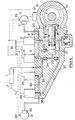
- the flow-control valve 40 comprises a spool 41 working in a bore 42 in the housing 5.
- the bore 42 has axially spaced radial ports 43, 44, 45, 46 and 47 of which the first two are connected directly to the master cylinder 1, the third 45 is on the downstream side of the one-way valve 23, and the fourth 46 is connected to the fifth 47 which, in turn, is disposed at the inner end of the bore 42 adjacent to the valve 8.
- a fourth radial port 48, opposite the third port 45, is connected to the brake 2, and an axial passage 49 in the end of the bore 42 leads to the valve 8.
- the spool 41 is provided with a longitudinally extending bore 50 which at the end adjacent to the valve 8 defines a restricted orifice 51 of reduced diameter.
- a transverse passage 52 connects the port 43 to the passage 50, and an annular groove 53 provides communication between the port 44 and the port 45.
- a face 55 at the one end of the groove 53 defines a knife-edge which co-operates with the port 44 to define a variable orifice.
- valve 8 closes at point C.
- the pump 10 pumps fluid from the expansion chamber 12 to the brake 2 and the master cylinder 1 but since the valve 8 has closed, the chamber 12 is not replenished from the brake.
- the brake is re-applied not only from the master cylinder 1 through the flow-control valve 40 and the orifice 51 but also from the pump 10 through the ports 45 and 48.
- the spool 41 moves relatively away from the valve 8 until point D is reached at which the spool 41 has returned to its original position and the port 46 is closed to isolate the pump 10 from the brake 2.
- the brake 2 is then re-applied during a second stage to point E only from the flow-control valve 40, and at a reduced rate of pressure increase.
- the anti-lock system of Figures 5 and 6 exhibits a two-rate re-apply feature and, as with the embodiments described above, retains the brake pressure at or above the maximum for a relatively long period. This ensures maximum braking efficiency and improved stopping distances.
Landscapes
- Engineering & Computer Science (AREA)
- Physics & Mathematics (AREA)
- Fluid Mechanics (AREA)
- Transportation (AREA)
- Mechanical Engineering (AREA)
- Regulating Braking Force (AREA)
Applications Claiming Priority (2)
| Application Number | Priority Date | Filing Date | Title |
|---|---|---|---|
| GB888802091A GB8802091D0 (en) | 1988-01-30 | 1988-01-30 | Improvements in hydraulic anti-lock braking systems for vehicles |
| GB8802091 | 1988-01-30 |
Publications (2)
| Publication Number | Publication Date |
|---|---|
| EP0327218A2 true EP0327218A2 (de) | 1989-08-09 |
| EP0327218A3 EP0327218A3 (en) | 1990-06-27 |
Family
ID=10630796
Family Applications (1)
| Application Number | Title | Priority Date | Filing Date |
|---|---|---|---|
| EP89300426A Ceased EP0327218A3 (en) | 1988-01-30 | 1989-01-18 | Improvements in hydraulic anti-lock braking systems for vehicles |
Country Status (4)
| Country | Link |
|---|---|
| US (1) | US4883327A (de) |
| EP (1) | EP0327218A3 (de) |
| JP (1) | JPH01262248A (de) |
| GB (1) | GB8802091D0 (de) |
Cited By (7)
| Publication number | Priority date | Publication date | Assignee | Title |
|---|---|---|---|---|
| GB2244316A (en) * | 1990-05-25 | 1991-11-27 | Teves Gmbh Alfred | Brake pressure control apparatus |
| EP0468834A1 (de) * | 1990-07-26 | 1992-01-29 | Alliedsignal Europe Services Techniques | Flüssigkeitspumpe mit hin- und hergehendem Kolben |
| EP0468833A1 (de) * | 1990-07-26 | 1992-01-29 | Alliedsignal Europe Services Techniques | Flüssigkeitspumpe mit hin- und hergehendem Kolben |
| FR2668547A1 (fr) * | 1990-10-30 | 1992-04-30 | Bendix Europ Services Tech | Pompe a piston alternatif comportant une chambre de sortie a volume variable, notamment pour circuit de freinage. |
| WO1992006874A1 (de) * | 1990-10-16 | 1992-04-30 | Alfred Teves Gmbh | Bremsdruckregelvorrichtung für eine hydraulische kraftfahrzeugbremsanlage |
| EP0525314A1 (de) * | 1991-07-29 | 1993-02-03 | ITT Automotive Europe GmbH | Hydraulikpumpe |
| WO1993008048A3 (de) * | 1991-10-18 | 1993-06-10 | Teves Gmbh Alfred | Blockiergeschützte hydraulische bremsanlage |
Families Citing this family (14)
| Publication number | Priority date | Publication date | Assignee | Title |
|---|---|---|---|---|
| DE69123479T2 (de) * | 1990-03-30 | 1997-07-03 | Akebono Brake Ind | Bremssteuereinheit |
| JP3016436B2 (ja) * | 1990-10-09 | 2000-03-06 | ボッシュブレーキシステム株式会社 | アンチスキッドブレーキ制御方法 |
| US5348382A (en) * | 1991-09-30 | 1994-09-20 | Ina Bearing Company, Inc. | Anti-lock brake system eccentric bearing arrangement including counterweight |
| DE4134490A1 (de) * | 1991-10-18 | 1993-04-22 | Teves Gmbh Alfred | Blockiergeschuetzte hydraulische bremsanlage |
| JPH06127363A (ja) * | 1992-10-14 | 1994-05-10 | Nippondenso Co Ltd | 車両用ブレーキ液圧制御装置 |
| US5722738A (en) * | 1993-07-23 | 1998-03-03 | Itt Automotive Europe Gmbh | Hydraulic brake system with brake slip control and traction slip control |
| JP3414033B2 (ja) * | 1995-03-13 | 2003-06-09 | トヨタ自動車株式会社 | ブレーキシステム |
| US5716111A (en) * | 1996-04-22 | 1998-02-10 | General Motors Corporation | Rotary actuated braking system |
| US6903813B2 (en) | 2002-02-21 | 2005-06-07 | Jjl Technologies Llc | Miniaturized system and method for measuring optical characteristics |
| US20030236489A1 (en) | 2002-06-21 | 2003-12-25 | Baxter International, Inc. | Method and apparatus for closed-loop flow control system |
| JP5962559B2 (ja) * | 2013-03-22 | 2016-08-03 | トヨタ自動車株式会社 | 車両挙動制御装置 |
| DE102017222546A1 (de) * | 2017-12-13 | 2019-06-13 | Robert Bosch Gmbh | Kolbenpumpe zur Förderung von Druckmittel in einem Druckmittelkreis |
| TWI644826B (zh) * | 2018-04-03 | 2018-12-21 | 彥豪金屬工業股份有限公司 | 自行車之防鎖死煞車機構 |
| IT202100018107A1 (it) * | 2021-07-09 | 2023-01-09 | Raicam Driveline S R L | Unità valvolare per un sistema di frenatura antibloccaggio |
Family Cites Families (15)
| Publication number | Priority date | Publication date | Assignee | Title |
|---|---|---|---|---|
| DE1655449B2 (de) * | 1967-09-26 | 1974-01-03 | Alfred Teves Gmbh, 6000 Frankfurt | Vorrichtung zum Verhindern des Blockierens eines Fahrzeugrades mit einer hydraulischen Bremsanlage |
| GB1227950A (de) * | 1967-10-31 | 1971-04-15 | ||
| GB1226345A (de) * | 1967-11-24 | 1971-03-24 | ||
| SE366698B (de) * | 1968-07-08 | 1974-05-06 | Teldix Gmbh | |
| DE1780058A1 (de) * | 1968-07-27 | 1972-01-20 | Teldix Gmbh | Antiblockierregelsystem fuer druckmittelbetaetigte Fahrzeugbremsen |
| GB1226346A (de) * | 1968-08-01 | 1971-03-24 | ||
| GB1248787A (en) * | 1968-12-13 | 1971-10-06 | Mullard Ltd | Improvements in or relating to anti-lock brake systems |
| US4179166A (en) * | 1970-06-26 | 1979-12-18 | U.S. Philips Corporation | Anti-lock vehicle brake system with variable decay rate |
| US3847449A (en) * | 1973-06-08 | 1974-11-12 | C Adahan | Solenoid powered brake pressure modulator |
| JPS5850903B2 (ja) * | 1975-08-14 | 1983-11-12 | ヤマハハツドウキ カブシキガイシヤ | アンチスキツドソウチ |
| US4099793A (en) * | 1976-08-12 | 1978-07-11 | Yamaha Hatsudoki Kabushiki Kaisha | Anti-skid vehicle brake system with fluid pressure actuated regulating valve |
| JPS5932549A (ja) * | 1982-08-17 | 1984-02-22 | Akebono Brake Ind Co Ltd | 車輪ロツク防止装置 |
| GB2161231B (en) * | 1984-07-04 | 1987-10-14 | Lucas Ind Plc | Anti-skid hydraulic braking systems for vehicles |
| DE3541742A1 (de) * | 1985-11-26 | 1987-05-27 | Bosch Gmbh Robert | Blockierschutzbremsanlage |
| GB8627378D0 (en) * | 1986-11-15 | 1986-12-17 | Lucas Ind Plc | Anti-lock braking systems |
-
1988
- 1988-01-30 GB GB888802091A patent/GB8802091D0/en active Pending
-
1989
- 1989-01-18 EP EP89300426A patent/EP0327218A3/en not_active Ceased
- 1989-01-19 US US07/299,402 patent/US4883327A/en not_active Expired - Fee Related
- 1989-01-30 JP JP1020684A patent/JPH01262248A/ja active Pending
Cited By (15)
| Publication number | Priority date | Publication date | Assignee | Title |
|---|---|---|---|---|
| GB2244316A (en) * | 1990-05-25 | 1991-11-27 | Teves Gmbh Alfred | Brake pressure control apparatus |
| GB2244316B (en) * | 1990-05-25 | 1994-05-25 | Teves Gmbh Alfred | Brake pressure control apparatus |
| US5176432A (en) * | 1990-05-25 | 1993-01-05 | Alfred Teves Gmbh | Brake pressure control apparatus |
| US5167495A (en) * | 1990-07-26 | 1992-12-01 | Bendix Europe Services Techniques | Reciprocating hydraulic pump |
| FR2665219A1 (fr) * | 1990-07-26 | 1992-01-31 | Bendix Europ Services Tech | Pompe hydraulique a cycle alternatif. |
| US5165875A (en) * | 1990-07-26 | 1992-11-24 | Bendix Europe Services Techniques | Reciprocating hydraulic pump |
| FR2665220A1 (fr) * | 1990-07-26 | 1992-01-31 | Bendix Europ Services Tech | Pompe hydraulique a cycle alternatif. |
| EP0468833A1 (de) * | 1990-07-26 | 1992-01-29 | Alliedsignal Europe Services Techniques | Flüssigkeitspumpe mit hin- und hergehendem Kolben |
| EP0468834A1 (de) * | 1990-07-26 | 1992-01-29 | Alliedsignal Europe Services Techniques | Flüssigkeitspumpe mit hin- und hergehendem Kolben |
| WO1992006874A1 (de) * | 1990-10-16 | 1992-04-30 | Alfred Teves Gmbh | Bremsdruckregelvorrichtung für eine hydraulische kraftfahrzeugbremsanlage |
| FR2668547A1 (fr) * | 1990-10-30 | 1992-04-30 | Bendix Europ Services Tech | Pompe a piston alternatif comportant une chambre de sortie a volume variable, notamment pour circuit de freinage. |
| EP0484192A1 (de) * | 1990-10-30 | 1992-05-06 | Alliedsignal Europe Services Techniques | Flüssigkeitspumpe |
| US5176428A (en) * | 1990-10-30 | 1993-01-05 | Bendix Europe Services Techniques | Hydraulic pump |
| EP0525314A1 (de) * | 1991-07-29 | 1993-02-03 | ITT Automotive Europe GmbH | Hydraulikpumpe |
| WO1993008048A3 (de) * | 1991-10-18 | 1993-06-10 | Teves Gmbh Alfred | Blockiergeschützte hydraulische bremsanlage |
Also Published As
| Publication number | Publication date |
|---|---|
| JPH01262248A (ja) | 1989-10-19 |
| US4883327A (en) | 1989-11-28 |
| GB8802091D0 (en) | 1988-02-24 |
| EP0327218A3 (en) | 1990-06-27 |
Similar Documents
| Publication | Publication Date | Title |
|---|---|---|
| US4883327A (en) | Hydraulic anti-lock braking systems for vehicles | |
| EP0202845B1 (de) | Hydraulischer Blockierverhinderer für Kraftfahrzeuge | |
| EP0332399B1 (de) | Hydraulisches Blockierschutzbremssystem für Fahrzeuge | |
| US4354715A (en) | Hydraulic anti-skid braking systems for vehicles | |
| US6203117B1 (en) | Compensator assembly in a hydraulic control unit for vehicular brake systems | |
| EP0358645B1 (de) | Traktionssteuerung mit abs-rückfördersystem | |
| US4779936A (en) | Anti-lock braking systems for vehicles | |
| GB2056606A (en) | Anti-skid braking systems for vehicles | |
| US4655513A (en) | Anti-skid hydraulic braking systems for vehicles | |
| US4892363A (en) | Anti-locking brake system | |
| GB2057613A (en) | Improvements in hydraulic anti-skid braking systems for vehicles | |
| US4636008A (en) | Anti-skid braking control system | |
| EP0343842B1 (de) | Hydraulisches Blockierschutzbremssystem für Fahrzeuge | |
| GB2161231A (en) | Anti-skid hydraulic braking systems for vehicles | |
| US5248190A (en) | Hydraulic braking pressure control system for vehicle | |
| EP0392815A1 (de) | Druckbetätigtes Bremssystem für Fahrzeuge | |
| US4941713A (en) | Hydraulic anti-lock braking systems for vehicles | |
| AU8327691A (en) | Regulator supply valve for adaptive braking and traction control systems | |
| US4725105A (en) | Simplified anti-lock braking system | |
| GB2109492A (en) | Improvements in hydraulic anti-skid braking systems for vehicles | |
| US4887871A (en) | Hydraulic anti-lock braking systems for vehicles | |
| GB2227061A (en) | Hydraulic anti-lock braking systems for vehicles | |
| GB2262580A (en) | Hydraulic anti-lock braking systems for vehicles |
Legal Events
| Date | Code | Title | Description |
|---|---|---|---|
| PUAI | Public reference made under article 153(3) epc to a published international application that has entered the european phase |
Free format text: ORIGINAL CODE: 0009012 |
|
| AK | Designated contracting states |
Kind code of ref document: A2 Designated state(s): DE FR GB IT |
|
| PUAL | Search report despatched |
Free format text: ORIGINAL CODE: 0009013 |
|
| AK | Designated contracting states |
Kind code of ref document: A3 Designated state(s): DE FR GB IT |
|
| 17P | Request for examination filed |
Effective date: 19901203 |
|
| 17Q | First examination report despatched |
Effective date: 19920414 |
|
| STAA | Information on the status of an ep patent application or granted ep patent |
Free format text: STATUS: THE APPLICATION HAS BEEN REFUSED |
|
| 18R | Application refused |
Effective date: 19950702 |