EP0327403A2 - Stellungsüberwachungsanordnung - Google Patents
Stellungsüberwachungsanordnung Download PDFInfo
- Publication number
- EP0327403A2 EP0327403A2 EP89301112A EP89301112A EP0327403A2 EP 0327403 A2 EP0327403 A2 EP 0327403A2 EP 89301112 A EP89301112 A EP 89301112A EP 89301112 A EP89301112 A EP 89301112A EP 0327403 A2 EP0327403 A2 EP 0327403A2
- Authority
- EP
- European Patent Office
- Prior art keywords
- switch
- output
- monitoring system
- terminal
- signal
- Prior art date
- Legal status (The legal status is an assumption and is not a legal conclusion. Google has not performed a legal analysis and makes no representation as to the accuracy of the status listed.)
- Withdrawn
Links
Images

Classifications
-
- H—ELECTRICITY
- H01—ELECTRIC ELEMENTS
- H01H—ELECTRIC SWITCHES; RELAYS; SELECTORS; EMERGENCY PROTECTIVE DEVICES
- H01H9/00—Details of switching devices, not covered by groups H01H1/00 - H01H7/00
- H01H9/16—Indicators for switching condition, e.g. "on" or "off"
- H01H9/167—Circuits for remote indication
Definitions
- This invention relates to a condition monitoring system and has particular reference, but not sole reference, to a system for monitoring the positions of switches in a car or other vehicle.
- Hitherto known switch monitoring systems either drive a small current continuously through each switch being monitored, or drive a large current through the switch momentarily.
- the total current consumption over a period of time can be excessive and cause the vehicle battery to be discharged if the vehicle is left at rest for too many days.
- the drive signal is of fixed duration and the monitoring unit has to respond immediately otherwise it will fail to read the condition of the switch.
- condition monitoring system arranged to provide at least first and second output drives to a device to be monitored and to receive at least first and second input signals from the monitored device, said device having a plurality of states and the system being further arranged to respond to the received input signals to select which output drive signal is applied to the device so that little or no current is drawn from the monitoring system by the device when the device is in any of its said states.
- the device being monitored is a two-state or two-position switch.
- the switch receives a low level output signal from the monitoring system so that it draws little or no current.
- the switch changes position, it receives a high level output signal via the new contact which is made, but an input of the monitoring system responds to this in order to apply a low level signal to the newly made contact. This ensures that little or no current is drawn by the switch in its new position.
- the system may be used in a vehicle to monitor lock switches in a central door locking system, or door switches controlling courtesy lamps.
- the system minimises the consumption of current. An instant of where this is particularly important is in the case of vehicles fitted with a burglar alarm system having a back-up battery, because the battery would be drained quite quickly if all the switches were continually drawing current.
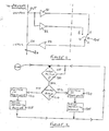
- a system for monitoring the condition of a switch SW which in this case comprises a two-position or two-state switch having a contact 10 connected at one end to a common point C and movable so that it makes either with point A or point B.
- the switch SW may form a lock switch in a central door locking system or a door switch controlling a courtesy lamp.
- the system will comprise a plurality of switches such as switch SW, each with its own set of the components shown which interconnect the switch SW with a central controller 20.
- the controller 20 has an output OUT driving a buffer B1 the output of which is connected to the switch contact A.
- the controller output also drives an inverting buffer B2 having its output connected to the switch contact B.
- the common point C of the switch is connected through a buffer B3 to an input IN of the controller.
- the controller 20 senses at step 100 whether the input IN is active (i.e. receiving current). Normally the input IN will be inactive: thus whilst the switch SW is in position A normally the output OUT of the controller will be providing a low level signal so that no current will pass through buffer B2 and switch 10 (via contact A) and buffer B3 to the controller input. So if at step 100 the input is found to be inactive, the controller 20 simply repeats step 100.
- Step 110 will then check the status of the output OUT and, finding it inactive, the controller will sense at step 120 that the switch is now in position B.
- the controller responds by driving the output OUT active i.e. to produce a high level signal.
- the output of inverting buffer B2 is now at low level so that no current flows from this through the switch and back to the controller input. Accordingly, the input IN remains inactive and step 100 will be repeated again until the switch is changed back from position B to position A.
- step 100 When eventually the switch is changed from position B to position A, step 100 will find that the input has become active, i.e. the high level which has been prevailing on the output OUT will now cause current to pass through buffer B1 and the switch (via contact A) and buffer B3 to the controller input IN.
- Step 110 then checks and on finding that the output is in its active condition, the controller determines that the switch is now in position A (step 130). Consequently, step 135 drives the output OUT to its inactive state. In this condition, no current is available to flow through buffer B2 and the switch contact A back to the controller input.
- the controller may comprise a hardware logic circuit or it may comprise a microprocessor, in either case having a low power mode which it normally adopts together with means for responding to the input IN to switch it to a high power mode for effecting the changeover action and then to return it to the low power mode immediately afterwards.
- FIG. 3 there is shown a modified monitoring system which responds to output sensing rather than input sensing of the central controller 20.
- the output OUT of the controller drives the switch contacts A and B through buffer B1 and inverting buffer B2 as in the system of Figure 1, but the common contact C of the switch is connected to ground. Also the contacts A and B are connected to respective inputs INA and INB of the controller through buffer B4 and B5.
- step 200 the output is driven active. Current fails to flow through the switch (contact A being broken), so that step 210 indicates that INA is active. Under this condition step 210 is repeated. Eventually however when the switch is changed from position B to position A, current will pass through buffer B1 and the switch to bring the input of buffer B4 to low level. Step 210 now finds that INA is inactive and step 220 determines that the switch is now in position A. Accordingly step 230 responds by driving the output inactive. This prevents current from flowing through buffer B1 and the switch via contact A. Step 240 will now monitor input INB repetitively, finding it active (high level), because inverting buffer B2 provides a high level signal which is sensed via buffer B5.
- step 240 Eventually when the switch is changed from position A to position B, step 240 will find that input INB has become inactive and step 250 determines that the switch is now in position B. Step 260 responds to drive the output OUT active. Now with the output at high level, the output of buffer B2 is low so no current is drawn through the switch and meanwhile the output of buffer B1 is high and the input INA registers as active. The controller now returns to the step 210, in effect monitoring for the next change in state of the switch SW.
- all inputs are high impedance inputs and all outputs are push-pull drivers.
- the "output” and "inverted output” signals may be generated separately within the controller.
Landscapes
- Keying Circuit Devices (AREA)
- Arrangements For Transmission Of Measured Signals (AREA)
Applications Claiming Priority (2)
| Application Number | Priority Date | Filing Date | Title |
|---|---|---|---|
| GB888802625A GB8802625D0 (en) | 1988-02-05 | 1988-02-05 | Condition monitoring system |
| GB8802625 | 1988-02-05 |
Publications (2)
| Publication Number | Publication Date |
|---|---|
| EP0327403A2 true EP0327403A2 (de) | 1989-08-09 |
| EP0327403A3 EP0327403A3 (de) | 1990-12-05 |
Family
ID=10631148
Family Applications (1)
| Application Number | Title | Priority Date | Filing Date |
|---|---|---|---|
| EP19890301112 Withdrawn EP0327403A3 (de) | 1988-02-05 | 1989-02-03 | Stellungsüberwachungsanordnung |
Country Status (2)
| Country | Link |
|---|---|
| EP (1) | EP0327403A3 (de) |
| GB (1) | GB8802625D0 (de) |
Cited By (2)
| Publication number | Priority date | Publication date | Assignee | Title |
|---|---|---|---|---|
| WO1997025729A1 (en) * | 1996-01-11 | 1997-07-17 | Fusion Meters Limited | Switch status sensor |
| GB2350951A (en) * | 1999-06-07 | 2000-12-13 | Ford Motor Co | Improved CMOS mechanical switch monitor circuit |
Family Cites Families (4)
| Publication number | Priority date | Publication date | Assignee | Title |
|---|---|---|---|---|
| DE1157296B (de) * | 1959-04-21 | 1963-11-14 | Bbc Brown Boveri & Cie | Rueckmelde- und Kontrollanordnung fuer die Schaltstellung eines Schuetzes oder fuer die Stellung eines mechanischen Geraetes |
| DE3001940C2 (de) * | 1980-01-21 | 1983-01-27 | Siemens AG, 1000 Berlin und 8000 München | Anordnung zur Ermittlung der Schaltstellung eines Schalters und zur Überwachung der zugehörigen Leitung auf Kurzschluß und Unterbrechung |
| DE3228686A1 (de) * | 1982-07-31 | 1984-02-02 | Edmund 7016 Gerlingen Zottnik | Verfahren und vorrichtung zur erfassung von sdchalterstellungen |
| FR2536903B1 (fr) * | 1982-11-29 | 1985-10-25 | Commissariat Energie Atomique | Dispositif de controle de l'etat d'un commutateur |
-
1988
- 1988-02-05 GB GB888802625A patent/GB8802625D0/en active Pending
-
1989
- 1989-02-03 EP EP19890301112 patent/EP0327403A3/de not_active Withdrawn
Cited By (3)
| Publication number | Priority date | Publication date | Assignee | Title |
|---|---|---|---|---|
| WO1997025729A1 (en) * | 1996-01-11 | 1997-07-17 | Fusion Meters Limited | Switch status sensor |
| US6255748B1 (en) | 1996-01-11 | 2001-07-03 | Fusion Meters Limited | Switch status sensor |
| GB2350951A (en) * | 1999-06-07 | 2000-12-13 | Ford Motor Co | Improved CMOS mechanical switch monitor circuit |
Also Published As
| Publication number | Publication date |
|---|---|
| GB8802625D0 (en) | 1988-03-02 |
| EP0327403A3 (de) | 1990-12-05 |
Similar Documents
| Publication | Publication Date | Title |
|---|---|---|
| US4812672A (en) | Selective connection of power supplies | |
| US4578591A (en) | Control circuit for automotive accessory system | |
| US6097241A (en) | ASIC low power activity detector to change threshold voltage | |
| EP0467512A2 (de) | Kommunikationssystem für Kraftfahrzeuge | |
| CA2042102A1 (en) | Mdi fault detection circuit with dual mode fault detection | |
| EP0321543A1 (de) | Laststeuersystem | |
| US5241582A (en) | Control for supplying power to car audio and phone systems | |
| EP1282273B1 (de) | System zur gesteuerten Abschaltung von Zweigen eines seriellen Kommunikationssytems in einem elektronischen Steuersystem für Bordgeräte eines Kraftfahrzeugs | |
| JP3524294B2 (ja) | スイッチ開閉状態検出回路 | |
| US5585781A (en) | Electric current control circuit for switches | |
| US5060300A (en) | Receiver switchable between network supply mode and power-conserving battery supply mode | |
| JP3435699B2 (ja) | 車両用負荷制御装置 | |
| JP2002185293A (ja) | マイコンの入力回路 | |
| JP3378768B2 (ja) | 電源切換回路 | |
| US5400021A (en) | Apparatus for controlling an operational panel | |
| CN111412630A (zh) | 一种通讯接口控制电路及空调机组 | |
| EP0055912A2 (de) | Multiplexvorrichtung für eine Schalteranordnung | |
| JPS6175912A (ja) | デバイス切換装置 | |
| US20240361817A1 (en) | Power supply control device and power supply control method | |
| JP3397550B2 (ja) | 電子回路 | |
| JPS57118954A (en) | Wiper control system | |
| JP2503299Y2 (ja) | 電源盤起動制御回路 | |
| JPH0454662Y2 (de) | ||
| JPH0378708B2 (de) | ||
| JPH0241260B2 (de) |
Legal Events
| Date | Code | Title | Description |
|---|---|---|---|
| PUAI | Public reference made under article 153(3) epc to a published international application that has entered the european phase |
Free format text: ORIGINAL CODE: 0009012 |
|
| AK | Designated contracting states |
Kind code of ref document: A2 Designated state(s): DE FR GB IT |
|
| PUAL | Search report despatched |
Free format text: ORIGINAL CODE: 0009013 |
|
| AK | Designated contracting states |
Kind code of ref document: A3 Designated state(s): DE FR GB IT |
|
| 17P | Request for examination filed |
Effective date: 19910604 |
|
| 17Q | First examination report despatched |
Effective date: 19930326 |
|
| STAA | Information on the status of an ep patent application or granted ep patent |
Free format text: STATUS: THE APPLICATION IS DEEMED TO BE WITHDRAWN |
|
| 18D | Application deemed to be withdrawn |
Effective date: 19930806 |