EP0327669A2 - Bohrfeinmessvorrichtung - Google Patents
Bohrfeinmessvorrichtung Download PDFInfo
- Publication number
- EP0327669A2 EP0327669A2 EP88113369A EP88113369A EP0327669A2 EP 0327669 A2 EP0327669 A2 EP 0327669A2 EP 88113369 A EP88113369 A EP 88113369A EP 88113369 A EP88113369 A EP 88113369A EP 0327669 A2 EP0327669 A2 EP 0327669A2
- Authority
- EP
- European Patent Office
- Prior art keywords
- dial
- probe
- gage
- members
- portions
- Prior art date
- Legal status (The legal status is an assumption and is not a legal conclusion. Google has not performed a legal analysis and makes no representation as to the accuracy of the status listed.)
- Granted
Links
Images

Classifications
-
- G—PHYSICS
- G01—MEASURING; TESTING
- G01B—MEASURING LENGTH, THICKNESS OR SIMILAR LINEAR DIMENSIONS; MEASURING ANGLES; MEASURING AREAS; MEASURING IRREGULARITIES OF SURFACES OR CONTOURS
- G01B3/00—Measuring instruments characterised by the use of mechanical techniques
- G01B3/22—Feeler-pin gauges, e.g. dial gauges
- G01B3/26—Plug gauges
Definitions
- the present invention relates to dial bore gages which are used for determining if the diameter and surface characteristics of cylindrical work surfaces are of some precise size and characteristic and, more particularly, to improved means for making fine adjustments between the probe tip and the movable pointer portion of the dial indicator associated with such gaging devices.
- the present means enables a user to more easily and more accurately adjust the movable dial indicator pointer to zero setting after the gaging contacts associated with the probe tip have been calibrated to a preset diameter thereby zeroing the dial indicator to a preset diameter on the probe tip prior to usage.
- Dial bore gages are specifically used to determine if the diameter and surface characteristics of cylindrical holes or bores are accurate to some known standard and such gages include gaging head members which gage the surfaces and have portions operatively connected to dial indicator means which indicate the condition and size of the hole or bore.
- Such dial bore gages are generally set and calibrated prior to usage based upon the final desired size or diameter of the bore to be gaged so that a user may quickly and accurately determine if the diameter and surface characteristics of such bore are of the desired size and finish, or if the diameter and surface finish is off by some amount, and if so, whether the bore is over or under size.
- This calibration is usually accomplished by placing the dial bore gage on a setting fixture, the setting fixture providing holding and supporting means for adjusting the alignment of the gaging contacts associated with the probe tip of a particular dial bore gage to the setting surfaces associated with the setting fixture. This procedure establishes the precise known distance between the gaging contacts and, based upon this known standard, the diameter and surface characteristics of a particular cylindrical hole or bore may be gaged.
- Typical of known setting fixtures is the fixture disclosed in Sunnen U.S. Patent No. 3,496,758 and the gage support means disclosed in co-pending Rutter et al U.S. patent application Serial No. 142,192, filed January 11, 1988.
- the gaging contacts associated with a particular dial bore gage have been set and calibrated, it is generally desired to reposition the movable pointers associated with the dial indicator to a zero setting to facilitate easy reading of the dial indicator to determine if the diameter and surface characteristics of the bore to be gaged are of the desired size and finish. If the gaging contacts are set to the desired finished size of the bore to be gaged as previously explained and the dial indicator reads zero, then, when the gage is positioned within the particular bore for the gaging thereof, the bore diameter will, if proper size, correspond to the desired finish diameter set between the gaging contacts. A reading other than zero on the dial indicator such as a plus or minus reading on the dial face indicates that the particular bore is either over or under size.
- Adjusting the movable pointers of the dial indicator to a zero reading has been accomplished in the past by using one of several known means.
- zeroing of the dial indicator may be accomplished by either slidably or rotatably moving the dial indicator face so as to align the zero index marking on the dial with the dial pointer, or by otherwise moving the indicator stem associated with the particular gage to reposition the movable pointer over the zero index marking. It is an advantage to be able to zero the movable pointer associated with the dial indicator prior to usage for various reasons including for convenience purposes and for ease of reading the dial indicator during a gaging process.
- Typical of the known dial setting means are the means disclosed in U.S. Patent Nos. 4,045,877; 4,476,634 and 4,477,977.
- None of the known means for zeroing a dial indicator to a preset diameter of the probe tip makes such an adjustment between the probe tip and the dial portion independent of any outside means such as a setting fixture as is true of the present invention.
- Such an adjustment mechanism is advantageous and desirable because it enables a user to make an appropriate accurate adjustment between the probe tip and the indicator means in order to establish a desired relationship therebetween.
- such an arrangement is advantageous because it eliminates the need for having a movable dial indicator face and other relatively complicated mechanisms for zeroing the movable dial pointers including means for holding and/or locking the dial indicator face against further movement at any desired position.
- the present construction facilitates replacing probe tips or gaging heads of different ranges on the same gaging device and such construction may also increase the operating range of a particular gaging head. All of the novel features and capabilities made possible by the present adjustment means represent important advancements in the gaging of internal cylindrical surfaces and bores.
- the present improvement reside in gage adjustment means that are positioned in the stem portion of a dial bore gage intermediate between the dial portion and the probe portion.
- the improvements include the provision of a threaded adjustment member rotatably mounted on the stem portion of the gage and having spaced threaded portions of slightly different pitch, one threaded portion cooperatively engaging a threaded portion of the same pitch on a gage stem attached to the housing for the dial portion of the gage and the other threaded portion of the adjustment member cooperatively engaging a threaded portion of the other pitch on a member that supports the probe or gaging head portion of the gage.
- the present improvement means also includes means resiliently urging the probe support means away from the dial portion of the gage to provide axial backlash compensation to improve the gage accuracy and response in all positions of adjustment. Additional means in the form of a screw and slot arrangement are provided between the probe support means and the dial indicator portion to prevent relative angular rotation between such members.
- the present improvements further include other resilient means, albeit weaker means, to maintain the operating arm of the dial indicator portion of the gage engaged with the probe portion.
- gage release mechanism which includes means operable to release pressure on the work engaging members so that the probe portion of the gage can be inserted into a bore to be gaged without any outward or radial force being applied to the gaging contacts or work engaging portions thereby minimizing the possibility of damage or wear on the work engaging members due to rubbing which is important to maintaining the accuracy and longevity of these members. This also reduces the possibility of damage to the internal bore surfce due to scratching or otherwise by the probe assembly. These are especially important considerations when gaging relatively deep bores and bores that have interruptions such as bores having "O" ring grooves, retaining ring grooves, spaced groove portions and bores that have other types of interruptions.
- the present dial bore gage improvements therefore provide a unique way for zeroing a dial indicator to some preset probe diameter; they improve gage accuracy and gage response; they provide both axial and angular backlash compensation between the probe tip and the dial indicator portions of the gage; and, as stated, they also provide a novel probe release feature which takes pressure off the work engaging elements thereby facilitating insertion and removal of the probe into and out of a bore to be gaged. These features make it easy to operate the gage and reduces wear on the work engaging gaging contacts.
- the present adjustment means allows the gage to achieve the full range of movement associated with the gaging contacts without disassembly of the entire unit. This is an important practical advantage not available to known gages where disassembly is required to fully utilize the range of the probe. Therefore, to some extent, the present adjustment means extends the operating range of each probe assembly mounted thereon. All of these features represent important advances in the setting means for dial bore gages including contributing greatly to the accuracy of such gages.
- improved means for adjusting the relative axial positions of the probe and dial portions of gages such as dial bore gages, for zeroing in a setting on a dial indicator portion of a dial bore gage to establish some desired probe diameter, for releasing pressure on the work engaging members of a dial bore gage to facilitate insertion and removal thereof into a bore and for reducing rubbing and abrading of the work engaging members on a dial bore gage.
- accuracy of dial bore gages is increased by providing backlash compensation between the probe and dial portions thereof.
- the life and accuracy of the work engaging members on a dial bore gage are extended and the necessity to relocate the dial portion of the dial bore gage to establish a predetermined setting condition is obviated. Finally the improved adjustment means allow to accurately set a dimension into a dial bore gage.
- the dial bore gage according to the invention is especially well suited for use with probe assemblies having pairs of opposed gaging and centralizing elements, and is simplified in its construction, operation and accuracy.
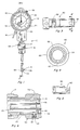
- the dial bore gage 10 of Fig. 1 and 2 and like measuring devices come in various sizes and shapes and generally include a dial portion 12 at one end thereof as shown in Fig. 1 for indicating a dimensional reading such as whether a bore diameter is over or under sized. This is determined by the gage reading when the gaging contacts of the device are in engagement with locations on a diameter of a bore being gaged.
- the gage 10 also includes a gaging or probe portion 14 having spaced and opposed work engaging contacts 66 and 68 for engaging the work surfce such as a bore surface that has been honed to some desired diameter.
- the gage 10 further includes an elongated connection or stem portion which extends between and connects the dial and probe portions 12 and 14, this connection portion of the gage including the present gage improvements and adjustment means 16.
- a probe pressure release lever 18 operatively connected to means for releasing pressure on the work engaging members is likewise provided to facilitate insertion and removal thereof into and out of a bore to be gaged as will be hereinafter further explained.
- the dial portion 12 of the present gage 10 includes a housing 20 which has an open-sided cavity 22 in which is positioned a rotatable dial assembly 24.
- the dial assembly 24 can be rotated in the cavity 22 and locked into any desired position by locking member 26.
- the provision of means for rotating the dial assembly 24 and means for locking the same represent a known means for zeroing the movable pointer associated with a particular dial indicator.
- Such features are obviated by the present gage adjustment means, and therefore may be eliminated from the gage. However, such features on a dial bore gage may be retained, if desired, to add further flexibility. It is mainly the construction and operation of the adjustment means 16 which are important to the present invention and represents the main novel features of the present gaging device.
- the dial housing 20 is shown mounted on a tubular member 30 which extends therefrom towards the probe assembly 14.
- the member 30 is pinned or keyed to another tubular member 32 by pin 34, and the member 32 extends into the dial housing 20 and accommodates a dial assembly extension member 36 which is connected to the dial assembly 24.
- the extension member 36 in turn slidably accommodates a further extension member 38 which, in turn, extends into a counterbore 39A in a dial operator member 39.
- the operator member 39 is movable axially and geared to change the positions of the rotatable indicator pointers 40 and 42 as best shown in Fig. 1.
- the dial assembly 24 is mounted or attached to the dial housing 20 in a conventional manner such as illustrated in Rutter U.S. Patent No. 4,045,877.
- the tubular member 30 functions as a dial assembly support means and includes an external threaded portion 44 located adjacent the end portion thereof which extends towards the probe assembly 14.
- the adjustment means 16 includes an adjustment member 17 having spaced internally threaded portions 46 and 48 of slightly different thread pitch, the internal threads 46 associated with one end of the adjustment member 17 being cooperatively engageable with the external threads 44 on the member 30.
- Another tubular member 50 (Figs. 2 and 3) has an externally threaded portion 52 located intermediate the respective opposite ends thereof and is slidably receivable within the member 30 as best shown in Fig. 2.
- the internal threads 48 associated with the adjustment member 17 are cooperatively engageable with the external threads 52 on the member 50.
- the tubular member 50 functions as support means for the probe assembly 14 and is constructed to receive the fixed probe portion 54 as shown in Fig. 2.
- the member 50 may be fixedly secured to the probe portion 54 by means such as set screw 56.
- the probe assembly 14 includes the elongated tubular member 54 which has a passageway or bore shown formed by communicating bore portions 58 and 60 which together extend therethrough from end-to-end.
- the bore portion 58 also receives a bushing 61 in its free end as shown.
- the bores 58 and 60 including the bushing 61 slidably receive a plunger assembly 62 which is positioned therein for axial movement.
- the plunger 62 includes a tapered forward end portion 64 adaptable for cooperatively engaging gaging and centralizing elements associated with the probe assembly 14 such as the ball-like gaging and centralizing members 66 and 68 shown in Fig. 1.
- Axial movements of the plunger 62 in a forward direction will displace the members 66 and 68 radially outwardly during a gaging operation. It is important to the present invention that when the probe member 54 is fixedly secured to the probe support means 50, the end surface 70 of the plunger 62 engages and bears against the terminal end surface of a member 72 which is attached to the dial operator member 39 as shown in Fig. 2. Since the probe member 54 is fixedly secured to the probe support member 50, axial movement of the member 50 will produce a corresponding axial movement of the member 54. This means that when the adjustment member 17 is rotated in either direction about the respective threaded portions 44 and 52, the plunger 62 will move axially relative to the members 54 and 50.
- gaging balls 66 and 68 are in a bore or between the fixed contacts of a setting fixture, this means that they will operate through the members 64 and 62 against the end of the member 39 to change the position of the pointers 40 and 42. This therefore enables the operator to very accurately zero the dial indicator to any desired diameter as will be further hereinafter explained.
- Resilient means in the form of a compression spring member 74 is positioned about the members 38 and 39 between the respective ends of the members 32 and 50 as shown in Fig. 2.
- the spring member 74 is a fairly strong spring and applies constant pressure to urge the probe support means 50 away from the dial portion 12 of the gage 10. This arrangement forces the respective cooperatively engageable threaded portions 44 and 46 and 48 and 52 into predetermined engagement with each other in all positions of adjustment of the member 17 thereby eliminating any looseness or play between the respective engaged threads. This acts to provide axial backlash compensation between the members 17, 30 and 50 thereby improving the gage accuracy and response in all positions of adjustment.
- a relative weaker compression spring 76 is also provided to maintain the operator arm 39 engaged with the end surface 70 of the plunger assembly 62.
- the spring member 76 is positioned about overlapping ends of the members 38 and 39 (Fig. 2) such that one end portion thereof engages and bears against one end of the extension member 36 while the opposite end engages an annular flange or retaining ring 78 on the member 39.
- the spring 76 applies pressure to constantly urge the terminal end portion 72 of the operator arm 39 into engagement with the end surface 70.
- the spring member 76 is weaker than the spring member 74 and its main purpose is to maintain the members 39 and 62 engaged and to a much lesser extent may provide a small amount of backlash compensation.
- the probe support means 50 also includes a tapered or beveled elongated slot 80 located adjacent the end thereof nearest the dial portion 12 as best shown in Figs. 4 and 5.
- the slot 80 slidably receives a tapered portion 84 of a locking element or screw 82 as best shown in Fig. 6.
- the locking element 82 is threadedly engaged with opening 83 in the dial support member 30.
- This screw and slot arrangement between the members 30 and 50 substantially eliminates relative angular but not relative axial movement therebetween. However, there should be sufficient clearance between the tapered portion 84 of the set screw 82 and the elongated slot 80 in the member 50 to enable the members 30 and 50 to move axially relative to each other.
- the probe support member 50 also has a flat 86 machined on it adjacent the same end thereof as the slot 80 as best shown in Figs. 2 and 3.
- a set screw 88 having a flat inner surface 89 is able to pass through opening 90 formed in the housing 20 to be threadedly positioned in threaded opening 92 in the member 30.
- the set screw 88 is used to lock member 50 in relation to member 30 axially once the gage has been set to the correct reading. This prevents accidentally changing the reading by either moving member 17, or by accidentally bumping or dropping the gage.
- the adjustment member 17 is rotated to move the aligned members 62 and 39 to reposition the movable pointers 40 and 42 to a zero setting on the dial face. This accurately zero sets the dimension being engaged by the gaging members 66 into the gage so that thereafter when the probe portion of the gage 10 is inserted into a bore it will indicate if the bore is of the desired diameter and if not how much it is over or under size.
- the engaged threaded portions 44 and 46 be of slightly different pitch than the engaged threaded portions 48 and 52 because it is this difference in thread pitch that enables the members 30 and 50 to move axially relative to each other during adjustment.
- the amount of difference in pitch thread will determine the rate of relative axial movement and the range of such axial movement between the members 30 and 50. For example, if the pitch of the threaded portions 44 and 46 is 32 threads per inch and the pitch of the threaded portions 48 and 52 is 40 threads per inch, one complete rotation of the adjustment member 17 in either direction will produce a corresponding relative axial movement between the members 30 and 50 of about .00625 inches.
- dial operator arm member 39 will move axially by this distance (assuming the gaging members 66 are held fixed) and this will produce rotation of the pointers 40 and 42 to establish a desired gage setting.
- the rate of change and the range of movement can be adjusted by selecting the thread pitches desired.
- the ability to precisely set the dial bore gage by zeroing the dial indicator to some desired reading in this manner prior to use allows the operator to achieve the full range of possible adjustment without moving the position of the dial portion of the gage as has been the practice with known dial bore gages.
- the adjustment member 17 is shown having a knurled outer surfce 94 (Fig. 1) which the operator grips when making an adjustment.
- the gage 10 also includes means 18 operable to release pressure on the work engaging members 66 and 68 so that the probe portion 14 can be inserted into a bore to be gaged without any outward or radial force being applied to the gaging contacts or work engaging portions thereby minimizing the possibility for damage or wear on the work engaging members due to rubbing on the work surface.
- the probe release lever 18 is operatively connected by bell crank means (not shown) to the member 96 (Fig. 2) such that movements of the release lever 18 inwardly towards the dial housing 20 will cause axial movement of the member 96 in the direction of the dial portion 12. This causes a retractor member 98 fixedly secured to the member 96 adjacent the end thereof to also move.
- the member 98 is connected to the member 96 by fastener member 100 (Fig.
- the retractor member 98 also extends through an oversized opening 104 (Fig. 2) formed in the member 30 and further extends through a slot 106 formed in the member 50 (Figs. 2 and 4) such that its terminal end portion is in spaced axial alignment with or overlaps the annular flange 78 on the member 39. As the member 96 moves toward the dial portion 12 during a retraction operation, the retractor member 98 likewise moves in the same direction and will move against the annular member 78.
- Fig. 7 is an enlarged fragmentary cross-sectional view of the central stem portion of the gage 10 of Fig. 2 illustrating in greater detail use of another embodiment 108 for the probe assembly.
- the probe assembly 108 like the probe assembly 14, is mounted in the probe support means 50 and includes a modified plunger assembly 110 as shown. Like the plunger assembly 62, the end portion 112 of the plunger 110 extends towards the dial portion 12 and engages the terminal end portion 72 of the dial operator arm 39. Operation of this embodiment is similar to that described above.
Landscapes
- Physics & Mathematics (AREA)
- General Physics & Mathematics (AREA)
- A Measuring Device Byusing Mechanical Method (AREA)
- Length-Measuring Instruments Using Mechanical Means (AREA)
Applications Claiming Priority (2)
| Application Number | Priority Date | Filing Date | Title |
|---|---|---|---|
| US154950 | 1988-02-11 | ||
| US07/154,950 US4809440A (en) | 1988-02-11 | 1988-02-11 | In dial bore gages |
Publications (3)
| Publication Number | Publication Date |
|---|---|
| EP0327669A2 true EP0327669A2 (de) | 1989-08-16 |
| EP0327669A3 EP0327669A3 (en) | 1990-06-13 |
| EP0327669B1 EP0327669B1 (de) | 1992-07-29 |
Family
ID=22553506
Family Applications (1)
| Application Number | Title | Priority Date | Filing Date |
|---|---|---|---|
| EP88113369A Expired EP0327669B1 (de) | 1988-02-11 | 1988-08-17 | Bohrfeinmessvorrichtung |
Country Status (6)
| Country | Link |
|---|---|
| US (1) | US4809440A (de) |
| EP (1) | EP0327669B1 (de) |
| JP (1) | JPH0769125B2 (de) |
| CA (1) | CA1302079C (de) |
| DE (1) | DE3873309T2 (de) |
| ES (1) | ES2034066T3 (de) |
Families Citing this family (19)
| Publication number | Priority date | Publication date | Assignee | Title |
|---|---|---|---|---|
| DE3922937A1 (de) * | 1989-07-12 | 1991-01-24 | Mauser Werke Oberndorf | Vorrichtung zum messen der innendurchmesser von rohren |
| US4936024A (en) * | 1989-10-26 | 1990-06-26 | Greenslade Joe E | Recess measuring device |
| US6822563B2 (en) | 1997-09-22 | 2004-11-23 | Donnelly Corporation | Vehicle imaging system with accessory control |
| US7339149B1 (en) | 1993-02-26 | 2008-03-04 | Donnelly Corporation | Vehicle headlight control using imaging sensor |
| US5877897A (en) | 1993-02-26 | 1999-03-02 | Donnelly Corporation | Automatic rearview mirror, vehicle lighting control and vehicle interior monitoring system using a photosensor array |
| US6861809B2 (en) | 1998-09-18 | 2005-03-01 | Gentex Corporation | Headlamp control to prevent glare |
| US6049171A (en) | 1998-09-18 | 2000-04-11 | Gentex Corporation | Continuously variable headlamp control |
| US6631316B2 (en) | 2001-03-05 | 2003-10-07 | Gentex Corporation | Image processing system to control vehicle headlamps or other vehicle equipment |
| US6130421A (en) | 1998-06-09 | 2000-10-10 | Gentex Corporation | Imaging system for vehicle headlamp control |
| US6338202B1 (en) | 2000-01-14 | 2002-01-15 | Thomas B. Brunner | Measurement tool used with an indicator |
| JP3510996B2 (ja) * | 2000-03-15 | 2004-03-29 | 株式会社ミツトヨ | ダイヤルゲージ |
| AU2003225228A1 (en) | 2002-05-03 | 2003-11-17 | Donnelly Corporation | Object detection system for vehicle |
| US7526103B2 (en) | 2004-04-15 | 2009-04-28 | Donnelly Corporation | Imaging system for vehicle |
| ITBO20070451A1 (it) * | 2007-06-29 | 2008-12-30 | Jobs Spa | Dispositivo di verifica delle dimensioni di svasature. |
| US8446470B2 (en) | 2007-10-04 | 2013-05-21 | Magna Electronics, Inc. | Combined RGB and IR imaging sensor |
| US9038283B2 (en) | 2011-09-14 | 2015-05-26 | Dorsey Metrology International | Bore gage system for setting and measuring large diameter bores |
| US9920840B2 (en) | 2014-08-08 | 2018-03-20 | Clark-Reliance Corporation | Valve with different threads for preventing rotation of and locking bonnet within valve |
| CN107941130B (zh) * | 2017-12-25 | 2023-10-27 | 京信通信技术(广州)有限公司 | 刻度显示装置及其归零调节机构 |
| US10788302B2 (en) * | 2018-09-07 | 2020-09-29 | Dorsey Metrology International | Modular mechanical bore gauge system |
Family Cites Families (4)
| Publication number | Priority date | Publication date | Assignee | Title |
|---|---|---|---|---|
| DE2160008B2 (de) * | 1971-12-03 | 1973-11-15 | Robert Bosch Gmbh, 7000 Stuttgart | Verfahren und Vorrichtung zur Herstellung eines Musters in einer auf einem Träger aufgedampften Metallschicht und dessen Verwendung |
| DE2462156C3 (de) * | 1974-01-09 | 1978-09-21 | Tesa S.A., Renens, Vaud (Schweiz) | Messdorn zum Messen des Innendurchmessers von Bohrungen o.dgl |
| US4045877A (en) * | 1976-03-11 | 1977-09-06 | Sunnen Products Company | Retractable dial bore gauge |
| JPS5863506U (ja) * | 1981-10-23 | 1983-04-28 | 株式会社ミツトヨ | シリンダゲ−ジ |
-
1988
- 1988-02-11 US US07/154,950 patent/US4809440A/en not_active Expired - Lifetime
- 1988-08-17 DE DE8888113369T patent/DE3873309T2/de not_active Expired - Lifetime
- 1988-08-17 ES ES198888113369T patent/ES2034066T3/es not_active Expired - Lifetime
- 1988-08-17 EP EP88113369A patent/EP0327669B1/de not_active Expired
- 1988-11-02 CA CA000582035A patent/CA1302079C/en not_active Expired - Lifetime
-
1989
- 1989-01-27 JP JP1019407A patent/JPH0769125B2/ja not_active Expired - Fee Related
Also Published As
| Publication number | Publication date |
|---|---|
| DE3873309T2 (de) | 1992-12-10 |
| JPH01227903A (ja) | 1989-09-12 |
| CA1302079C (en) | 1992-06-02 |
| JPH0769125B2 (ja) | 1995-07-26 |
| EP0327669A3 (en) | 1990-06-13 |
| DE3873309D1 (de) | 1992-09-03 |
| EP0327669B1 (de) | 1992-07-29 |
| ES2034066T3 (es) | 1993-04-01 |
| US4809440A (en) | 1989-03-07 |
Similar Documents
| Publication | Publication Date | Title |
|---|---|---|
| US4809440A (en) | In dial bore gages | |
| US4731931A (en) | Caliper system | |
| US4045877A (en) | Retractable dial bore gauge | |
| US5182862A (en) | Indicating thread gage | |
| WO2007058610A1 (en) | Adjustment device for a measuring head | |
| US6832440B2 (en) | Spindle squaring device and method of operation | |
| US7069666B2 (en) | Spindle squaring apparatus | |
| US4419830A (en) | Bore gauge head assembly | |
| US4553337A (en) | Thread gauge for measuring thread pitch diameters | |
| US4419829A (en) | Head for bore gauge | |
| WO2002037051A1 (en) | Bore gage with deflection levers (cleaning) | |
| KR920006497B1 (ko) | 다이얼 구멍 게이지와 같은 측정구를 세팅할시 이를 지지하기 위한 지지장치 | |
| US5456017A (en) | Adjustable holder for the fine adjustment of a dial gauge | |
| US4228595A (en) | Tool setting gage | |
| US4126940A (en) | Adjustable fork gauge | |
| US4058901A (en) | Plug gage | |
| US4974327A (en) | Adjustable three-point thread measuring device | |
| EP0327670B1 (de) | Kalibrierkopf für Bohrfeinmessvorrichtungen | |
| US4335518A (en) | Thread gaging instrument | |
| EP0105979B1 (de) | Kopf für Bohrlochmesser | |
| CN101027534A (zh) | 带有不作旋转螺纹测杆的螺旋千分尺 | |
| US3638324A (en) | Gage | |
| US4434557A (en) | Indicator snap gage assemblies | |
| US4989331A (en) | Gage | |
| US4432141A (en) | High precision height comparator apparatus |
Legal Events
| Date | Code | Title | Description |
|---|---|---|---|
| PUAI | Public reference made under article 153(3) epc to a published international application that has entered the european phase |
Free format text: ORIGINAL CODE: 0009012 |
|
| AK | Designated contracting states |
Kind code of ref document: A2 Designated state(s): BE CH DE ES FR GB IT LI NL SE |
|
| PUAL | Search report despatched |
Free format text: ORIGINAL CODE: 0009013 |
|
| AK | Designated contracting states |
Kind code of ref document: A3 Designated state(s): BE CH DE ES FR GB IT LI NL SE |
|
| 17P | Request for examination filed |
Effective date: 19900702 |
|
| 17Q | First examination report despatched |
Effective date: 19910502 |
|
| GRAA | (expected) grant |
Free format text: ORIGINAL CODE: 0009210 |
|
| AK | Designated contracting states |
Kind code of ref document: B1 Designated state(s): BE CH DE ES FR GB IT LI NL SE |
|
| ET | Fr: translation filed | ||
| REF | Corresponds to: |
Ref document number: 3873309 Country of ref document: DE Date of ref document: 19920903 |
|
| ITF | It: translation for a ep patent filed | ||
| REG | Reference to a national code |
Ref country code: ES Ref legal event code: FG2A Ref document number: 2034066 Country of ref document: ES Kind code of ref document: T3 |
|
| PLBE | No opposition filed within time limit |
Free format text: ORIGINAL CODE: 0009261 |
|
| STAA | Information on the status of an ep patent application or granted ep patent |
Free format text: STATUS: NO OPPOSITION FILED WITHIN TIME LIMIT |
|
| 26N | No opposition filed | ||
| PGFP | Annual fee paid to national office [announced via postgrant information from national office to epo] |
Ref country code: FR Payment date: 19930729 Year of fee payment: 6 |
|
| PGFP | Annual fee paid to national office [announced via postgrant information from national office to epo] |
Ref country code: GB Payment date: 19930730 Year of fee payment: 6 Ref country code: ES Payment date: 19930730 Year of fee payment: 6 |
|
| PGFP | Annual fee paid to national office [announced via postgrant information from national office to epo] |
Ref country code: BE Payment date: 19930812 Year of fee payment: 6 |
|
| PGFP | Annual fee paid to national office [announced via postgrant information from national office to epo] |
Ref country code: SE Payment date: 19930817 Year of fee payment: 6 |
|
| PGFP | Annual fee paid to national office [announced via postgrant information from national office to epo] |
Ref country code: NL Payment date: 19930831 Year of fee payment: 6 |
|
| PGFP | Annual fee paid to national office [announced via postgrant information from national office to epo] |
Ref country code: CH Payment date: 19931028 Year of fee payment: 6 |
|
| PGFP | Annual fee paid to national office [announced via postgrant information from national office to epo] |
Ref country code: DE Payment date: 19931029 Year of fee payment: 6 |
|
| PG25 | Lapsed in a contracting state [announced via postgrant information from national office to epo] |
Ref country code: GB Effective date: 19940817 |
|
| PG25 | Lapsed in a contracting state [announced via postgrant information from national office to epo] |
Ref country code: SE Effective date: 19940818 Ref country code: ES Free format text: LAPSE BECAUSE OF NON-PAYMENT OF DUE FEES Effective date: 19940818 |
|
| PG25 | Lapsed in a contracting state [announced via postgrant information from national office to epo] |
Ref country code: LI Effective date: 19940831 Ref country code: CH Effective date: 19940831 Ref country code: BE Effective date: 19940831 |
|
| EAL | Se: european patent in force in sweden |
Ref document number: 88113369.8 |
|
| BERE | Be: lapsed |
Owner name: SUNNEN PRODUCTS CY Effective date: 19940831 |
|
| PG25 | Lapsed in a contracting state [announced via postgrant information from national office to epo] |
Ref country code: NL Effective date: 19950301 |
|
| NLV4 | Nl: lapsed or anulled due to non-payment of the annual fee | ||
| GBPC | Gb: european patent ceased through non-payment of renewal fee |
Effective date: 19940817 |
|
| PG25 | Lapsed in a contracting state [announced via postgrant information from national office to epo] |
Ref country code: FR Effective date: 19950428 |
|
| REG | Reference to a national code |
Ref country code: CH Ref legal event code: PL |
|
| PG25 | Lapsed in a contracting state [announced via postgrant information from national office to epo] |
Ref country code: DE Effective date: 19950503 |
|
| EUG | Se: european patent has lapsed |
Ref document number: 88113369.8 |
|
| REG | Reference to a national code |
Ref country code: FR Ref legal event code: ST |
|
| REG | Reference to a national code |
Ref country code: ES Ref legal event code: FD2A Effective date: 19990503 |
|
| PG25 | Lapsed in a contracting state [announced via postgrant information from national office to epo] |
Ref country code: IT Free format text: LAPSE BECAUSE OF NON-PAYMENT OF DUE FEES;WARNING: LAPSES OF ITALIAN PATENTS WITH EFFECTIVE DATE BEFORE 2007 MAY HAVE OCCURRED AT ANY TIME BEFORE 2007. THE CORRECT EFFECTIVE DATE MAY BE DIFFERENT FROM THE ONE RECORDED. Effective date: 20050817 |