EP0327672A2 - Rotor avec une anticulation de battement ou centre du rotor - Google Patents
Rotor avec une anticulation de battement ou centre du rotor Download PDFInfo
- Publication number
- EP0327672A2 EP0327672A2 EP88114496A EP88114496A EP0327672A2 EP 0327672 A2 EP0327672 A2 EP 0327672A2 EP 88114496 A EP88114496 A EP 88114496A EP 88114496 A EP88114496 A EP 88114496A EP 0327672 A2 EP0327672 A2 EP 0327672A2
- Authority
- EP
- European Patent Office
- Prior art keywords
- rotor
- drive shaft
- rod
- flapping
- centre
- Prior art date
- Legal status (The legal status is an assumption and is not a legal conclusion. Google has not performed a legal analysis and makes no representation as to the accuracy of the status listed.)
- Ceased
Links
Images


Classifications
-
- B—PERFORMING OPERATIONS; TRANSPORTING
- B64—AIRCRAFT; AVIATION; COSMONAUTICS
- B64C—AEROPLANES; HELICOPTERS
- B64C27/00—Rotorcraft; Rotors peculiar thereto
- B64C27/32—Rotors
- B64C27/37—Rotors having articulated joints
- B64C27/41—Rotors having articulated joints with flapping hinge or universal joint, common to the blades
Definitions
- the invention relates to a rotor according to the preamble of patent claim 1.
- the rotor was previously driven by means of the drive shaft via so-called tow bars. With this, when turning the blades, the rotor can be driven uniformly, i.e. Do not achieve synchronism with the drive shaft. Accordingly, among other things mass forces from the rotor's accelerations are to be expected, which not only put an additional load on its structure, but also on the gearbox of the drive shaft. In addition, there can be forced deformations in the driving linkage (tow bars).
- the invention is therefore based on the object of ensuring the same synchronism with its drive shaft in a rotor of the aforementioned type.
- the invention also has the advantage that it can be conducive to the dynamic or running stability of the rotor through the restoring torque effects of the spiral springs resulting from leaf angle movements due to the design of the mounting of the individual handlebars that can be rotated through the angles.
- the rotors shown e.g. for a tilting wing aircraft, those of the so-called semi-rigid construction with an articulated blade connection of all rotor blades 1 in the rotor center by means of an angularly movable spherical plain bearing 2 are preferably in the form of an elastomeric bearing.
- Its inner spherical bearing part 2.1 is connected to a rotor drive shaft 3, whereas the outer bearing part 2.2 is embedded in a rigid rotor hub 4 which unites the rotor blades 1.
- both bearing parts 2.1, 2.2 consist of metal and are connected by an elastomeric intermediate part 2.3 made of alternating rubber and metal layers.
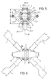
- the rotation of the rotor blades 1 is effected by means of the drive shaft 3 by rotating the rotor hub 4 via one (Fig. 1, 2) or more (Fig. 3, 4, 5, 6) driver each in the form of a link 5.
- the individual link 5 consists of two rods 5.1, 5.2 of the same length connected by an angularly movable spherical bearing 6, one of which has a rod 5.1 the drive shaft 3 and the other rod 5.2 is connected to the rotor hub 4 so that it can rotate in the direction of the blade.
- the pivot point of the two pivots 7 in question per link 5 must lie on the central axis 3.1 of the rotor drive shaft 3 or, according to FIGS. 3, 5, on a parallel line 3.1.1. Furthermore there must be the same distance a between the pivot point of the individual pivot joint 7 and the center of the rotor or spherical bearing 2.
- the pivot points of the rotary joints 7 are also arranged at the same distance b from the central axis 3.1 of the rotor drive shaft 3. 1, 2 with only one link 5, these driver arrangements have the advantage of a torque transmission without lateral force with respect to the articulated bearing 2 of the rotor.
- the handlebars 5 can become integral parts of the rotor hub 4 by means of these resilient swivel joints 7, the structure of which then expediently consists of fiber-reinforced plastic.
Landscapes
- Engineering & Computer Science (AREA)
- Mechanical Engineering (AREA)
- Aviation & Aerospace Engineering (AREA)
- Support Of The Bearing (AREA)
- Preliminary Treatment Of Fibers (AREA)
- Structures Of Non-Positive Displacement Pumps (AREA)
- Wind Motors (AREA)
Applications Claiming Priority (2)
| Application Number | Priority Date | Filing Date | Title |
|---|---|---|---|
| DE3804203 | 1988-02-11 | ||
| DE19883804203 DE3804203C1 (fr) | 1988-02-11 | 1988-02-11 |
Publications (2)
| Publication Number | Publication Date |
|---|---|
| EP0327672A2 true EP0327672A2 (fr) | 1989-08-16 |
| EP0327672A3 EP0327672A3 (fr) | 1990-07-11 |
Family
ID=6347168
Family Applications (1)
| Application Number | Title | Priority Date | Filing Date |
|---|---|---|---|
| EP88114496A Ceased EP0327672A3 (fr) | 1988-02-11 | 1988-09-06 | Rotor avec une anticulation de battement ou centre du rotor |
Country Status (2)
| Country | Link |
|---|---|
| EP (1) | EP0327672A3 (fr) |
| DE (1) | DE3804203C1 (fr) |
Cited By (2)
| Publication number | Priority date | Publication date | Assignee | Title |
|---|---|---|---|---|
| EP1228961A3 (fr) * | 2001-02-02 | 2002-12-18 | Agusta S.p.A. | Transmission à vitesse constante pour rotor d'aéronef |
| WO2010140933A1 (fr) * | 2009-06-02 | 2010-12-09 | Saab Ab | Amortisseur de rotor et rotor anticouple comportant un tel amortisseur de rotor |
Family Cites Families (11)
| Publication number | Priority date | Publication date | Assignee | Title |
|---|---|---|---|---|
| FR630465A (fr) * | 1926-05-31 | 1927-12-03 | Propulseur ou sustentateur à correction automatique | |
| FR631596A (fr) * | 1926-06-18 | 1927-12-22 | Sustentateur avec régulateur | |
| US2961051A (en) * | 1955-11-17 | 1960-11-22 | Wilford Edward Burke | Rotor hub and drive system |
| DE2414570C2 (de) * | 1974-03-26 | 1976-01-22 | Messerschmitt-Bölkow-Blohm GmbH, 8000 München | Drehflügelflugzeug mit zumindest einer Taumelscheibe zur zyklischen und kollektiven Blattsteuerung |
| US4115031A (en) * | 1974-04-12 | 1978-09-19 | Textron, Inc. | Hub spring moment isolation in underslung two-bladed teetering rotor |
| US4333728A (en) * | 1977-08-11 | 1982-06-08 | Textron, Inc. | Compound hub spring system for helicopters |
| US4566856A (en) * | 1984-09-27 | 1986-01-28 | United Technologies Corporation | Helicopter gimbal rotor |
| US4569629A (en) * | 1984-09-27 | 1986-02-11 | United Technologies Corporation | Helicopter gimbal rotor |
| US4695227A (en) * | 1985-02-27 | 1987-09-22 | Hughes Helicopters Inc. | All composite, constant speed universal joint for use in a shaft driven tiltable main rotor for a helicopter |
| US4681511A (en) * | 1985-09-30 | 1987-07-21 | The Boeing Company | Low vibration helicopter rotor |
| US4708591A (en) * | 1986-01-15 | 1987-11-24 | Stephan Roman | Bladed aircraft rotor with flexible blade mountings |
-
1988
- 1988-02-11 DE DE19883804203 patent/DE3804203C1/de not_active Expired
- 1988-09-06 EP EP88114496A patent/EP0327672A3/fr not_active Ceased
Cited By (4)
| Publication number | Priority date | Publication date | Assignee | Title |
|---|---|---|---|---|
| EP1228961A3 (fr) * | 2001-02-02 | 2002-12-18 | Agusta S.p.A. | Transmission à vitesse constante pour rotor d'aéronef |
| US6607357B2 (en) | 2001-02-02 | 2003-08-19 | Agusta S.P.A. | Aircraft constant-velocity transmission rotor |
| WO2010140933A1 (fr) * | 2009-06-02 | 2010-12-09 | Saab Ab | Amortisseur de rotor et rotor anticouple comportant un tel amortisseur de rotor |
| US9073636B2 (en) | 2009-06-02 | 2015-07-07 | Saab Ab | Rotor damper and tail rotor with such a rotor damper |
Also Published As
| Publication number | Publication date |
|---|---|
| DE3804203C1 (fr) | 1989-08-17 |
| EP0327672A3 (fr) | 1990-07-11 |
Similar Documents
| Publication | Publication Date | Title |
|---|---|---|
| EP1502851B1 (fr) | Propulseur aerodynamique a poussee verticale | |
| DE2922469C2 (de) | Rotor für ein Drehflügelflugzeug | |
| DE3608600C2 (de) | Zentrierteil für eine Taumelscheibe | |
| DE2419922C2 (de) | Steuereinrichtung für ein Drehflügel-Flugzeug | |
| DE2800075A1 (de) | Hubschrauberquerholmrotor | |
| DE3001207A1 (de) | Gelenk-rotor fuer hubschrauber | |
| DE1556414C3 (de) | Rotor fur Drehflügelflugzeuge | |
| DE2210767A1 (de) | Lager für ein Rotorblatt eines Drehflügelflugzeuges | |
| DE2755557A1 (de) | Hubschrauberrotor | |
| EP1500588B1 (fr) | Procede pour creer une portance et une poussee verticale | |
| DE2838792A1 (de) | Hubschrauber | |
| EP1613534B1 (fr) | Rotor et giravion equipe d'un rotor de ce type | |
| DE2638148B2 (de) | Rotor für ein Drehflügelflugzeug | |
| EP0351577A2 (fr) | Rotor, en particulier pour un avion à voilure tournante | |
| EP0048799A1 (fr) | Rotor pour aéronefs à voilure tournante | |
| DE2611245A1 (de) | Rotor fuer drehfluegelflugzeuge | |
| DE2932441C2 (de) | Dämpfungseinrichtung für ein Rotorblatt | |
| DE2733101B2 (de) | Schlag- und schwenkgelenklose Rotorblattlagerung | |
| EP0327672A2 (fr) | Rotor avec une anticulation de battement ou centre du rotor | |
| DE1172961B (de) | Drehfluegelflugzeug | |
| EP0067952A1 (fr) | Rotor avec jonction pale-moyen, ayant une pied de pale flexible permettant les mouvements de torsion, de trainée et de battement | |
| EP1201538B1 (fr) | Dispositif de commande des pales du rotor | |
| DE2945195A1 (de) | Hubschrauberrotor | |
| DE2745468A1 (de) | Rotor eines drehfluegelflugzeugs | |
| DE2414570C2 (de) | Drehflügelflugzeug mit zumindest einer Taumelscheibe zur zyklischen und kollektiven Blattsteuerung |
Legal Events
| Date | Code | Title | Description |
|---|---|---|---|
| PUAI | Public reference made under article 153(3) epc to a published international application that has entered the european phase |
Free format text: ORIGINAL CODE: 0009012 |
|
| AK | Designated contracting states |
Kind code of ref document: A2 Designated state(s): DE ES FR GB IT NL |
|
| PUAL | Search report despatched |
Free format text: ORIGINAL CODE: 0009013 |
|
| AK | Designated contracting states |
Kind code of ref document: A3 Designated state(s): DE ES FR GB IT NL |
|
| 17P | Request for examination filed |
Effective date: 19900606 |
|
| 17Q | First examination report despatched |
Effective date: 19910808 |
|
| STAA | Information on the status of an ep patent application or granted ep patent |
Free format text: STATUS: THE APPLICATION HAS BEEN REFUSED |
|
| 18R | Application refused |
Effective date: 19920127 |