EP0327708A2 - Vorrichtung zum Auslösen von Schnellverbindungen, die ein modulares Gerät für unterstützende Profilelemente befestigt - Google Patents
Vorrichtung zum Auslösen von Schnellverbindungen, die ein modulares Gerät für unterstützende Profilelemente befestigt Download PDFInfo
- Publication number
- EP0327708A2 EP0327708A2 EP88120983A EP88120983A EP0327708A2 EP 0327708 A2 EP0327708 A2 EP 0327708A2 EP 88120983 A EP88120983 A EP 88120983A EP 88120983 A EP88120983 A EP 88120983A EP 0327708 A2 EP0327708 A2 EP 0327708A2
- Authority
- EP
- European Patent Office
- Prior art keywords
- cap
- release
- apparata
- slot
- quick
- Prior art date
- Legal status (The legal status is an assumption and is not a legal conclusion. Google has not performed a legal analysis and makes no representation as to the accuracy of the status listed.)
- Granted
Links
- 230000008878 coupling Effects 0.000 title claims abstract description 39
- 238000010168 coupling process Methods 0.000 title claims abstract description 39
- 238000005859 coupling reaction Methods 0.000 title claims abstract description 39
- 238000003780 insertion Methods 0.000 description 3
- 230000037431 insertion Effects 0.000 description 3
- 239000003086 colorant Substances 0.000 description 1
- 239000004020 conductor Substances 0.000 description 1
- 230000000670 limiting effect Effects 0.000 description 1
- 239000000463 material Substances 0.000 description 1
- 238000012986 modification Methods 0.000 description 1
- 230000004048 modification Effects 0.000 description 1
Images

Classifications
-
- H—ELECTRICITY
- H02—GENERATION; CONVERSION OR DISTRIBUTION OF ELECTRIC POWER
- H02B—BOARDS, SUBSTATIONS OR SWITCHING ARRANGEMENTS FOR THE SUPPLY OR DISTRIBUTION OF ELECTRIC POWER
- H02B1/00—Frameworks, boards, panels, desks, casings; Details of substations or switching arrangements
- H02B1/015—Boards, panels, desks; Parts thereof or accessories therefor
- H02B1/04—Mounting thereon of switches or of other devices in general, the switch or device having, or being without, casing
- H02B1/052—Mounting on rails
-
- H—ELECTRICITY
- H01—ELECTRIC ELEMENTS
- H01H—ELECTRIC SWITCHES; RELAYS; SELECTORS; EMERGENCY PROTECTIVE DEVICES
- H01H9/00—Details of switching devices, not covered by groups H01H1/00 - H01H7/00
- H01H9/02—Bases, casings, or covers
- H01H9/0264—Protective covers for terminals
-
- H—ELECTRICITY
- H02—GENERATION; CONVERSION OR DISTRIBUTION OF ELECTRIC POWER
- H02B—BOARDS, SUBSTATIONS OR SWITCHING ARRANGEMENTS FOR THE SUPPLY OR DISTRIBUTION OF ELECTRIC POWER
- H02B1/00—Frameworks, boards, panels, desks, casings; Details of substations or switching arrangements
- H02B1/015—Boards, panels, desks; Parts thereof or accessories therefor
- H02B1/04—Mounting thereon of switches or of other devices in general, the switch or device having, or being without, casing
- H02B1/041—Mechanical coupling for side-by-side mounted apparatus
-
- H—ELECTRICITY
- H02—GENERATION; CONVERSION OR DISTRIBUTION OF ELECTRIC POWER
- H02B—BOARDS, SUBSTATIONS OR SWITCHING ARRANGEMENTS FOR THE SUPPLY OR DISTRIBUTION OF ELECTRIC POWER
- H02B1/00—Frameworks, boards, panels, desks, casings; Details of substations or switching arrangements
- H02B1/015—Boards, panels, desks; Parts thereof or accessories therefor
- H02B1/04—Mounting thereon of switches or of other devices in general, the switch or device having, or being without, casing
- H02B1/052—Mounting on rails
- H02B1/0523—Mounting on rails locked into position by a sliding member
Definitions
- the present invention relates to a device for releasing conventional block-like elements, termed quick couplings, which are normally used to removably secure modular apparata, and more particularly electric devices, such as differential switches, having a cap for protecting the electric connections which lead to the terminals of said devices, to their supporting profiled elements.
- the aim of the present invention is therefore to provide a device for releasing quick couplings securing the above described modular apparata which is capable of allowing the easy and rapid release or disconnection of the modular apparatus from its supporting profiled element even in the presence of the cap for the protection of the electric connection cables.
- Another object of the invention is to provide a release device structured so as to allow the simultaneous release of a plurality of quick couplings, provided on a multipolar apparatus or the like, using a single rod-like element.
- Not least object of the invention is to provide a release device which is structurally simple, such as to not create increases in the bulk of the apparatus or significant increases in its cost.
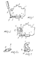
- Figure 1 illustrates an electric switch 1, with movable contacts which can be reset by means of a lever 2, which is removably secured to a wall or to a supporting plane by means of a conventional "quick coupling" 3; more precisely, this embodiment has, on the face opposite to the one bearing the lever 2, an inclined tooth 4 and, in an opposite and spaced position, a step 5 substantially defining a right angle.
- a profiled supporting element 6 is fixed to the wall and has the shape of an omega, i.e. a profiled element the opposite longitudinal edges whereof are folded outwards so as to form two opposite hooks 7-7a.
- the device 1 is stably secured to the profiled element 6 by means of a coupling element 3, substantially a dowel which is force inserted (normally due to the action of a spring embedded therein) between the hook 7a of the profiled element and the tooth 5 of the apparatus; assembly is therefore performed by inserting the inclined step 4 below the hook 7 of the profiled element 6 and then moving the base of the apparatus to rest on the hooks 7-7a and subsequently force hooking the element 3 between the hook 7a and the tooth 5.
- said quick coupling 3 has a slot or opening 8 so that by inserting therein the end of a screwdriver 9 (or another rod like tool) and by levering on the edge 10 of the apparatus the quick coupling 3 is moved away from the profiled element 6 and then partially rotated about the step 5 until it exits from its seat, thus releasing the apparatus.
- the release of the quick coupling 3 is easy in the case of apparata such as those of figure 1, while in the case of apparata having a front cap 11 for protecting the connecting conductors 12 which lead to the terminals 13, as indicated schematically in figure 2, the insertion of the end of the screwdriver may be impossible, so that the release of the quick coupling 3 must be performed by means of special tools and in a time-consuming manner.
- the insertion of the inclined tooth 15 in the slot 8 of the coupling 3 is also easily performed during the snap engagement of the cap onto the apparatus, i.e. by first of all inserting the tooth 15 into the slot 8 and then rotating the cap against the apparatus until it locks thereon.
- the cap provided with said L-shaped release element allows to simultaneously release, with a single screwdriver, two or more quick couplings provided on a multipolar device 18 (figure 6) possibly constituted by a plurality of poles arranged side by side on a single profiled element 6.
- a multipolar device 18 possibly constituted by a plurality of poles arranged side by side on a single profiled element 6.
- This solution provides a plurality of inclined teeth 15-15a-15b etc. (figure 6) protruding from a single crosspiece or strip 19 and engageable in the slots 8 of the individual quick couplings; in this manner, with a single screwdriver inserted in the single slot 20 which protrudes outwards from the strip 11 and by levering on the cap, all the teeth 15-15a-15b etc. are simultaneously pulled in the same direction, thus simultaneously releasing all the quick couplings.
- This in practice avoids the need to use two or more screwdrivers simultaneously to remove the multipolar device from its supporting profiled element 6.
Landscapes
- Engineering & Computer Science (AREA)
- Power Engineering (AREA)
- Mounting Components In General For Electric Apparatus (AREA)
- Clamps And Clips (AREA)
- Manufacturing Of Electrical Connectors (AREA)
- Details Of Connecting Devices For Male And Female Coupling (AREA)
- Spinning Or Twisting Of Yarns (AREA)
- Quick-Acting Or Multi-Walled Pipe Joints (AREA)
- Manipulator (AREA)
- Automatic Assembly (AREA)
- Snaps, Bayonet Connections, Set Pins, And Snap Rings (AREA)
Priority Applications (1)
| Application Number | Priority Date | Filing Date | Title |
|---|---|---|---|
| AT88120983T ATE87407T1 (de) | 1987-12-17 | 1988-12-15 | Vorrichtung zum ausloesen von schnellverbindungen, die ein modulares geraet fuer unterstuetzende profilelemente befestigt. |
Applications Claiming Priority (2)
| Application Number | Priority Date | Filing Date | Title |
|---|---|---|---|
| IT2307087 | 1987-12-17 | ||
| IT23070/87A IT1223521B (it) | 1987-12-17 | 1987-12-17 | Dispositivo per lo sgancio degli attacchi rapidi utilizzati per il fissaggio di apparecchi modulari ai relativi profilati di sostegno |
Publications (3)
| Publication Number | Publication Date |
|---|---|
| EP0327708A2 true EP0327708A2 (de) | 1989-08-16 |
| EP0327708A3 EP0327708A3 (en) | 1989-10-18 |
| EP0327708B1 EP0327708B1 (de) | 1993-03-24 |
Family
ID=11203463
Family Applications (1)
| Application Number | Title | Priority Date | Filing Date |
|---|---|---|---|
| EP88120983A Expired - Lifetime EP0327708B1 (de) | 1987-12-17 | 1988-12-15 | Vorrichtung zum Auslösen von Schnellverbindungen, die ein modulares Gerät für unterstützende Profilelemente befestigt |
Country Status (4)
| Country | Link |
|---|---|
| EP (1) | EP0327708B1 (de) |
| AT (1) | ATE87407T1 (de) |
| DE (1) | DE3879671D1 (de) |
| IT (1) | IT1223521B (de) |
Cited By (8)
| Publication number | Priority date | Publication date | Assignee | Title |
|---|---|---|---|---|
| EP0528341A3 (de) * | 1991-08-17 | 1994-04-20 | Metrawatt Gmbh Gossen | |
| EP0874433A3 (de) * | 1997-04-21 | 1998-11-25 | Siemens Aktiengesellschaft | Auf Tragschienen aufschnappbares Gerät |
| WO2000060712A1 (de) * | 1999-04-06 | 2000-10-12 | Siemens Aktiengesellschaft | Geräteanordnung |
| WO2002043092A1 (de) * | 2000-11-23 | 2002-05-30 | Moeller Gmbh | Elektrische anordnung |
| CN102695397A (zh) * | 2011-03-23 | 2012-09-26 | 凤凰通讯发展及制造股份有限公司 | 用于将电源基座安装到din导轨上的闭锁组件及方法 |
| WO2016128169A1 (de) * | 2015-02-12 | 2016-08-18 | Weidmüller Interface GmbH & Co. KG | ANORDNUNG MEHRERER RASTFÜßE FÜR EINE BAUGRUPPE UND BAUGRUPPE |
| CN112576869A (zh) * | 2019-09-27 | 2021-03-30 | 台达电子工业股份有限公司 | 电源模块 |
| US20220416519A1 (en) * | 2021-06-25 | 2022-12-29 | Abb Schweiz Ag | Device insertion and removal method for electrical equipment |
Family Cites Families (3)
| Publication number | Priority date | Publication date | Assignee | Title |
|---|---|---|---|---|
| FR2233732B1 (de) * | 1973-06-15 | 1976-04-30 | Unelec | |
| FR2328312A1 (fr) * | 1975-10-16 | 1977-05-13 | Schutzapparate Paris & Co | Disposition de compteurs horaires de fonctionnement et appareils similaires dans une installation de distribution |
| DE7609710U1 (de) * | 1976-03-29 | 1976-09-16 | Siemens Ag, 1000 Berlin Und 8000 Muenchen | Installationsgerät, beispielsweise Reihenklemme |
-
1987
- 1987-12-17 IT IT23070/87A patent/IT1223521B/it active
-
1988
- 1988-12-15 AT AT88120983T patent/ATE87407T1/de not_active IP Right Cessation
- 1988-12-15 DE DE8888120983T patent/DE3879671D1/de not_active Expired - Lifetime
- 1988-12-15 EP EP88120983A patent/EP0327708B1/de not_active Expired - Lifetime
Cited By (14)
| Publication number | Priority date | Publication date | Assignee | Title |
|---|---|---|---|---|
| EP0528341A3 (de) * | 1991-08-17 | 1994-04-20 | Metrawatt Gmbh Gossen | |
| EP0874433A3 (de) * | 1997-04-21 | 1998-11-25 | Siemens Aktiengesellschaft | Auf Tragschienen aufschnappbares Gerät |
| WO2000060712A1 (de) * | 1999-04-06 | 2000-10-12 | Siemens Aktiengesellschaft | Geräteanordnung |
| US6834765B1 (en) | 1999-04-06 | 2004-12-28 | Siemens Aktiengellschaft | Series installation device arrangement |
| WO2002043092A1 (de) * | 2000-11-23 | 2002-05-30 | Moeller Gmbh | Elektrische anordnung |
| EP2503645A3 (de) * | 2011-03-23 | 2013-05-01 | Phoenix Contact GmbH & Co. KG | Riegelbaugruppe zur Montage einer Stromversorgungsbasis für einen Prozessfeldbus auf einer DIN-Schiene, und Verfahren |
| CN102695397A (zh) * | 2011-03-23 | 2012-09-26 | 凤凰通讯发展及制造股份有限公司 | 用于将电源基座安装到din导轨上的闭锁组件及方法 |
| US8469737B2 (en) | 2011-03-23 | 2013-06-25 | Phoenix Contact Development & Manufacturing, Inc. | Latch assembly for mounting power supply base for a process fieldbus on a DIN rail and method |
| CN102695397B (zh) * | 2011-03-23 | 2015-11-25 | 凤凰通讯两合有限公司 | 用于将电源基座安装到din导轨上的闭锁组件及方法 |
| WO2016128169A1 (de) * | 2015-02-12 | 2016-08-18 | Weidmüller Interface GmbH & Co. KG | ANORDNUNG MEHRERER RASTFÜßE FÜR EINE BAUGRUPPE UND BAUGRUPPE |
| US10263399B2 (en) | 2015-02-12 | 2019-04-16 | Weidmüller Interface GmbH & Co. KG | Multiple latching feet for electrical connector assembly |
| CN112576869A (zh) * | 2019-09-27 | 2021-03-30 | 台达电子工业股份有限公司 | 电源模块 |
| US20220416519A1 (en) * | 2021-06-25 | 2022-12-29 | Abb Schweiz Ag | Device insertion and removal method for electrical equipment |
| US11563311B2 (en) * | 2021-06-25 | 2023-01-24 | Abb Schweiz Ag | Device insertion and removal method for electrical equipment |
Also Published As
| Publication number | Publication date |
|---|---|
| DE3879671D1 (de) | 1993-04-29 |
| IT8723070A0 (it) | 1987-12-17 |
| ATE87407T1 (de) | 1993-04-15 |
| EP0327708B1 (de) | 1993-03-24 |
| IT1223521B (it) | 1990-09-19 |
| EP0327708A3 (en) | 1989-10-18 |
Similar Documents
| Publication | Publication Date | Title |
|---|---|---|
| US4165443A (en) | Power distribution system | |
| AU2001233549B2 (en) | Quick connecting universal electrical box and wiring system | |
| US5662496A (en) | Fuse junction box | |
| JP2758134B2 (ja) | コネクタ保持用アダプタとパッチパネルシステム | |
| US4191443A (en) | Electrical connector means | |
| EP0470471A2 (de) | Paneel-Befestigungsbügel | |
| EP0258980A2 (de) | Verbindung von Flachkabel-Steckverbindern | |
| CA2614101A1 (en) | Modular wall housing unit for electrical components | |
| AU2001233549A1 (en) | Quick connecting universal electrical box and wiring system | |
| EP0327708B1 (de) | Vorrichtung zum Auslösen von Schnellverbindungen, die ein modulares Gerät für unterstützende Profilelemente befestigt | |
| DK148548B (da) | Trefaset konnektor | |
| US11862946B2 (en) | Bus bar system with at least one bus bar held in a contact protection housing | |
| US5525068A (en) | Electric power busway plug connector shutter arrangement | |
| EP0644617A1 (de) | Verbinder mit Arretiervorrichtung für Kontaktelemente | |
| US5382176A (en) | Electrical connectors | |
| US3812450A (en) | Relay socket | |
| US4332330A (en) | Electrical cut-in box | |
| NO148940B (no) | Elektrisk koblingsboks | |
| SE464789B (sv) | Eldosa till montering i kabelskena | |
| GB2283134A (en) | Terminal block | |
| GB2056179A (en) | The mounting of circuit breakers | |
| GB2098011A (en) | Electrical sockets | |
| FI68484B (fi) | Anordning vid eldosa | |
| EP0374918A1 (de) | Aufschnappbares Gehäuse und damit zusammenwirkende Plattenöffnung zum Montieren eines elektrischen Steckers | |
| FI93157C (fi) | Laite kaapelijohdinten liittämiseksi kaukoviestintätekniikan dropwire-liitoslistojen leikkuuliitinkoskettimiin |
Legal Events
| Date | Code | Title | Description |
|---|---|---|---|
| PUAI | Public reference made under article 153(3) epc to a published international application that has entered the european phase |
Free format text: ORIGINAL CODE: 0009012 |
|
| AK | Designated contracting states |
Kind code of ref document: A2 Designated state(s): AT BE CH DE ES FR GB GR IT LI LU NL SE |
|
| PUAL | Search report despatched |
Free format text: ORIGINAL CODE: 0009013 |
|
| AK | Designated contracting states |
Kind code of ref document: A3 Designated state(s): AT BE CH DE ES FR GB GR IT LI LU NL SE |
|
| 17P | Request for examination filed |
Effective date: 19900305 |
|
| 17Q | First examination report despatched |
Effective date: 19920407 |
|
| RAP1 | Party data changed (applicant data changed or rights of an application transferred) |
Owner name: ABB ELETTROCONDUTTURE S.P.A. |
|
| GRAA | (expected) grant |
Free format text: ORIGINAL CODE: 0009210 |
|
| AK | Designated contracting states |
Kind code of ref document: B1 Designated state(s): AT BE CH DE ES FR GB GR IT LI LU NL SE |
|
| PG25 | Lapsed in a contracting state [announced via postgrant information from national office to epo] |
Ref country code: SE Effective date: 19930324 Ref country code: NL Effective date: 19930324 Ref country code: LI Effective date: 19930324 Ref country code: GR Free format text: LAPSE BECAUSE OF FAILURE TO SUBMIT A TRANSLATION OF THE DESCRIPTION OR TO PAY THE FEE WITHIN THE PRESCRIBED TIME-LIMIT Effective date: 19930324 Ref country code: ES Free format text: THE PATENT HAS BEEN ANNULLED BY A DECISION OF A NATIONAL AUTHORITY Effective date: 19930324 Ref country code: DE Effective date: 19930324 Ref country code: CH Effective date: 19930324 Ref country code: AT Effective date: 19930324 |
|
| REF | Corresponds to: |
Ref document number: 87407 Country of ref document: AT Date of ref document: 19930415 Kind code of ref document: T |
|
| REF | Corresponds to: |
Ref document number: 3879671 Country of ref document: DE Date of ref document: 19930429 |
|
| ET | Fr: translation filed | ||
| ITF | It: translation for a ep patent filed | ||
| REG | Reference to a national code |
Ref country code: CH Ref legal event code: PL |
|
| NLV1 | Nl: lapsed or annulled due to failure to fulfill the requirements of art. 29p and 29m of the patents act | ||
| PG25 | Lapsed in a contracting state [announced via postgrant information from national office to epo] |
Ref country code: GB Effective date: 19931215 |
|
| PG25 | Lapsed in a contracting state [announced via postgrant information from national office to epo] |
Ref country code: LU Free format text: LAPSE BECAUSE OF NON-PAYMENT OF DUE FEES Effective date: 19931231 |
|
| PLBE | No opposition filed within time limit |
Free format text: ORIGINAL CODE: 0009261 |
|
| STAA | Information on the status of an ep patent application or granted ep patent |
Free format text: STATUS: NO OPPOSITION FILED WITHIN TIME LIMIT |
|
| 26N | No opposition filed | ||
| GBPC | Gb: european patent ceased through non-payment of renewal fee |
Effective date: 19931215 |
|
| PGFP | Annual fee paid to national office [announced via postgrant information from national office to epo] |
Ref country code: BE Payment date: 20021205 Year of fee payment: 15 |
|
| PGFP | Annual fee paid to national office [announced via postgrant information from national office to epo] |
Ref country code: FR Payment date: 20021206 Year of fee payment: 15 |
|
| PG25 | Lapsed in a contracting state [announced via postgrant information from national office to epo] |
Ref country code: BE Free format text: LAPSE BECAUSE OF NON-PAYMENT OF DUE FEES Effective date: 20031231 |
|
| BERE | Be: lapsed |
Owner name: *ABB ELETTROCONDUTTURE S.P.A. Effective date: 20031231 |
|
| PG25 | Lapsed in a contracting state [announced via postgrant information from national office to epo] |
Ref country code: FR Free format text: LAPSE BECAUSE OF NON-PAYMENT OF DUE FEES Effective date: 20040831 |
|
| REG | Reference to a national code |
Ref country code: FR Ref legal event code: ST |
|
| PG25 | Lapsed in a contracting state [announced via postgrant information from national office to epo] |
Ref country code: IT Free format text: LAPSE BECAUSE OF NON-PAYMENT OF DUE FEES;WARNING: LAPSES OF ITALIAN PATENTS WITH EFFECTIVE DATE BEFORE 2007 MAY HAVE OCCURRED AT ANY TIME BEFORE 2007. THE CORRECT EFFECTIVE DATE MAY BE DIFFERENT FROM THE ONE RECORDED. Effective date: 20051215 |