EP0327752A2 - Dispositif à coins de retenue et d'étanchéité pour tête de puits - Google Patents
Dispositif à coins de retenue et d'étanchéité pour tête de puits Download PDFInfo
- Publication number
- EP0327752A2 EP0327752A2 EP88308835A EP88308835A EP0327752A2 EP 0327752 A2 EP0327752 A2 EP 0327752A2 EP 88308835 A EP88308835 A EP 88308835A EP 88308835 A EP88308835 A EP 88308835A EP 0327752 A2 EP0327752 A2 EP 0327752A2
- Authority
- EP
- European Patent Office
- Prior art keywords
- slip
- retainer ring
- seal assembly
- bowl
- assembly
- Prior art date
- Legal status (The legal status is an assumption and is not a legal conclusion. Google has not performed a legal analysis and makes no representation as to the accuracy of the status listed.)
- Withdrawn
Links
Images

Classifications
-
- E—FIXED CONSTRUCTIONS
- E21—EARTH OR ROCK DRILLING; MINING
- E21B—EARTH OR ROCK DRILLING; OBTAINING OIL, GAS, WATER, SOLUBLE OR MELTABLE MATERIALS OR A SLURRY OF MINERALS FROM WELLS
- E21B33/00—Sealing or packing boreholes or wells
- E21B33/02—Surface sealing or packing
- E21B33/03—Well heads; Setting-up thereof
- E21B33/04—Casing heads; Suspending casings or tubings in well heads
- E21B33/0422—Casing heads; Suspending casings or tubings in well heads a suspended tubing or casing being gripped by a slip or an internally serrated member
-
- Y—GENERAL TAGGING OF NEW TECHNOLOGICAL DEVELOPMENTS; GENERAL TAGGING OF CROSS-SECTIONAL TECHNOLOGIES SPANNING OVER SEVERAL SECTIONS OF THE IPC; TECHNICAL SUBJECTS COVERED BY FORMER USPC CROSS-REFERENCE ART COLLECTIONS [XRACs] AND DIGESTS
- Y10—TECHNICAL SUBJECTS COVERED BY FORMER USPC
- Y10S—TECHNICAL SUBJECTS COVERED BY FORMER USPC CROSS-REFERENCE ART COLLECTIONS [XRACs] AND DIGESTS
- Y10S285/00—Pipe joints or couplings
- Y10S285/91—Gaskets
Definitions
- the present invention relates to an improved wellhead slip and seal assembly including a slip assembly with slips supported in a slip bowl and with the seal assembly positioned above and interconnected to the slip assembly.
- the seal assembly includes a segmented retainer ring which is at least partially radially compressible and having inner and outer recesses in which resilient sealing rings are positioned and the retainer ring has an outer diameter at such recesses which is larger than the inner diameter of the housing in which it is to be positioned and includes an external tapered surface from said outer diameter to a smaller outer diameter therebelow which is smaller than the inner diameter of the housing so that the retainer ring is moved radially inwardly as it is moved into position within said wellhead housing.
- An object of the present invention is to provide an improved wellhead slip and sealing assembly in which the resilient seals are protected from being loaded by the load carried by the slip and bowl and are protected from extrusion due to high pressure loading.
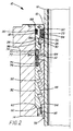
- Slip and seal assembly 10 as shown in FIGURE 1 is the preferred form of the present invention and is illustrated in position assembled around string 12 and partially within wellhead housing 14.
- Slip and seal assembly 10 includes retainer ring 16 having outer groove 18 in which resilient sealing ring 20 is positioned, inner flange 22, the under surface of which forms shoulder 24 against which inner resilient sealing ring 25 is positioned and inner recess 26 having upper and lower end surfaces 28 and 30 which both taper upwardly and inwardly; slip bowl 32 having separate anti-extrusion device 34 positioned in its upper end within dovetail recess 36 as shown, outer projection 38 having upper and lower tapered surfaces 40 and 42 and, in assembled condition, projection 38 extends into seal ring recess 26, internal slip camming surfaces 44 on the lower portion of slip bowl 32 and an intermediate offset portion 46 extending between the upper portion to the lower portion of slip bowl 32; and slips 48 positioned within the lower portion of slip bowl 32 and having external camming surfaces 50 mating and in engagement with the internal camming surfaces 44 on slip bowl 32 and internal gripping teeth 52
- each of slips 48 below camming surfaces 44 includes cylindrical surface 54 and low angle setting surface 56.
- Resilient fingers 58 supported from the lower portion of slip bowl 32 engage low angle setting surface 56 on slips 48 to urge it inwardly and to create the initial engagement of gripping slips 48 with the exterior of string 12.
- Fingers 58 are integral with ring 58a which is secured within the lower portion of slip bowl 32 by press fit pins 58b as shown. It is preferred that fingers 58 be individual resilient elements engaging surface 56 but if desired they could be a single skirt engaging all of the setting surfaces 56 of the slips 48 to ensure that the initial setting of the slips 48 against the exterior of string 12 is provided with the initial downward movement of the string within assembly 10.
- slip and seal assembly 10 When it is desired that slip and seal assembly 10 support the weight of string 12, the weight of string 12 is gradually released to be exerted on slips 48 and with slip and seal assembly 10 being seated with seating shoulder 60 on the lower outer end of slip bowl 32 being in engagement with housing seat 62 the entire weight of string 12 may be released to assembly 10 and it will be transmitted by slips 48 and slip bowl 32 to housing seat 62.
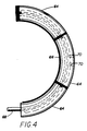
- each half ring 66 includes two openings 70 extending upwardly therein from their lower side to receive locating pins 72 which are positioned in bores 74 in offset portion 46 of slip bowl 32 as best shown in FIGURES 1 and 2.
- Pins 72 are biased upwardly toward openings 70 by springs 76 and pins 78 are secured to pins 72 to limit their upward travel by the engagement of pins 78 with shoulders 80 at the upper end of counterbores 82 in which pins 72 and springs 76 are positioned.
- Slip bowl 32 is also made in two half sections with end pins 84 providing interengagement and with suitable connecting means (not shown), such as bolts or other suitable latching mechanism or connecting means.
- suitable connecting means such as bolts or other suitable latching mechanism or connecting means.
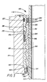
- FIGURE 2 the movement of assembly 10 downward within wellhead housing 14 continues until seating shoulder 60 on the lower portion of slip bowl 32 comes into engagement with housing seat 62.
- the exterior tapered surface 86 of retainer ring 16 engages tapered surface 88 within the upper portion of wellhead housing 14 and cams retainer ring 16 inwardly to move inner resilient sealing ring 25 into sealing engagement with the exterior of string 12.
- outer resilient sealing ring 20 is sufficiently large that it projects slightly beyond the outer diameter of retainer ring 16 to ensure sealing against the inner surface of housing 14.
- Pins 72 function to attache retainer ring 16 to slip bowl 32, to orient the split in ring 16 with respect to the split in slip bowl 32, to act as top latching arrangement for slip bowl halves, to act as stops to prevent outward movement of seal ring halves 66, to allow freedom of inward movement of retainer ring 16 during seal energization, and to ensure concentricity of retainer ring 16 with respect to slip bowl 32 to ease installation through a blowout preventer stack and into mating preparation.
- Slip and seal assembly 110 shown in FIGURE 3, is substantially identical with seal assembly 10 and components which are identical have the same numbers with the prefix "1" in their designations.
- Seal assembly 110 includes sealing ring 92 which includes anti-extrusion devices 94, such as ropes or other suitable devices, embedded in the upper and lower inner corners and in the outer lower corner as shown. Also, assembly 110 does not include separate anti-extrusion device 34. With this configuration, sealing ring 92 is reinforced at the three corners and this assists in the retention of its shape when it is exposed to pressure.
- assembly 10 and 110 While both assembly 10 and 110 have been shown with the anti-extrusion devices, it is considered that no such devices may be needed in all cases.
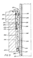
- Slip and seal assembly 210 shown in FIGURE 5, illustrates such structure and is the second modification of the preferred form of the invention.
- assembly 210 includes all of the components of assembly 10 with the same part numbers except that the components in FIGURE 5 include the prefix number "2" in their designation.
- Assembly 210 is exactly like assemblies 10 and 110 except that it does not include any anti-extrusion device for the protection of its sealing ring 225.
- Slip and seal assembly 10, 110 and 210 are installed in the following steps with reference being made only to the components of assembly 10.
- the halves of slip bowl 32 are installed around string 12 with the pins 84 positioned within the recesses in the other of the bowl halves and the assembled slip bowl 32 is then temporarily supported above the blowout preventer stack or the bowl preparation using suitable material.
- the bottom of slip bowl 32 at the splits is secured using bolts or other suitable latching mechanism.
- Halves 66 of seal assembly are installed around string 12 above slip bowl 32 with pins 68 positioned within the mating holes in the other half 66.
- the split of retainer ring 16 is oriented to be ninety degrees from the split of slip bowl 32.
- Pins 72 are depressed until sufficient vertical space if provided to allow outer projection 38 on slip bowl 32 to enter within recess 26 in retainer ring 16. This also positions the lower portion of retainer ring 16 within the recess formed below projection 38 and the offset portion 46 of slip bowl 32. Pins 72 should be positioned within openings 70 in ring 16. Assembly 10 should be relieved of its temporary support and with slips 48 free to move relative to bowl 32, assembly 10 is lowered until tapered surface 86 on retainer ring 16 engages tapered surface 88 on the upper interior of housing 14. The sealing portion of slip and seal assembly 10 is energized by reducing tension in string 12.
Landscapes
- Life Sciences & Earth Sciences (AREA)
- Engineering & Computer Science (AREA)
- Geology (AREA)
- Mining & Mineral Resources (AREA)
- Physics & Mathematics (AREA)
- Environmental & Geological Engineering (AREA)
- Fluid Mechanics (AREA)
- General Life Sciences & Earth Sciences (AREA)
- Geochemistry & Mineralogy (AREA)
- Excavating Of Shafts Or Tunnels (AREA)
- Gasket Seals (AREA)
- Earth Drilling (AREA)
Applications Claiming Priority (2)
| Application Number | Priority Date | Filing Date | Title |
|---|---|---|---|
| US153224 | 1988-02-08 | ||
| US07/153,224 US4828293A (en) | 1988-02-08 | 1988-02-08 | Wellhead slip and seal assembly |
Publications (2)
| Publication Number | Publication Date |
|---|---|
| EP0327752A2 true EP0327752A2 (fr) | 1989-08-16 |
| EP0327752A3 EP0327752A3 (fr) | 1990-04-11 |
Family
ID=22546288
Family Applications (1)
| Application Number | Title | Priority Date | Filing Date |
|---|---|---|---|
| EP88308835A Withdrawn EP0327752A3 (fr) | 1988-02-08 | 1988-09-23 | Dispositif à coins de retenue et d'étanchéité pour tête de puits |
Country Status (6)
| Country | Link |
|---|---|
| US (1) | US4828293A (fr) |
| EP (1) | EP0327752A3 (fr) |
| JP (1) | JPH01210592A (fr) |
| BR (1) | BR8900499A (fr) |
| CA (1) | CA1305049C (fr) |
| NO (1) | NO890497L (fr) |
Cited By (1)
| Publication number | Priority date | Publication date | Assignee | Title |
|---|---|---|---|---|
| EP0359355B1 (fr) * | 1988-08-08 | 1994-03-30 | Cooper Industries, Inc. | Garniture d'étanchéité à coins pour une tête à puits |
Families Citing this family (5)
| Publication number | Priority date | Publication date | Assignee | Title |
|---|---|---|---|---|
| US6834718B2 (en) * | 2001-12-21 | 2004-12-28 | Stream-Flo Industries, Ltd. | Casing head connector with landing base |
| US8479824B2 (en) * | 2008-10-02 | 2013-07-09 | Weatherford/Lamb, Inc. | Power slip assembly for wellhead casing and wellbore tubing |
| US11112039B2 (en) * | 2019-05-30 | 2021-09-07 | Guangzhou Jst Seals Technology Co., Ltd. | Slip sealing structure |
| CN114961625A (zh) * | 2021-02-27 | 2022-08-30 | 洪泽东俊机械有限公司 | 一种页岩气井口管柱悬吊装置加工方法 |
| US12404729B2 (en) * | 2023-07-31 | 2025-09-02 | Consolidated Rig Works, L.P. | Omnidirectional slip bowl |
Family Cites Families (7)
| Publication number | Priority date | Publication date | Assignee | Title |
|---|---|---|---|---|
| US1984806A (en) * | 1933-06-03 | 1934-12-18 | S R Dresser Mfg Co | Gasket for pipe joints and clamps |
| US2496154A (en) * | 1947-02-14 | 1950-01-31 | Cameron Iron Works Inc | Packoff |
| US3095627A (en) * | 1954-05-14 | 1963-07-02 | Mcevoy Co | Pipe anchor |
| US3038745A (en) * | 1957-05-02 | 1962-06-12 | Alco Products Inc | Well head seal with means to limit compression of the seal |
| US3188118A (en) * | 1963-05-27 | 1965-06-08 | Cameron Iron Works Inc | Pipe holding apparatus |
| US3329448A (en) * | 1964-08-24 | 1967-07-04 | Cameron Iron Works Inc | Pipe hanging apparatus |
| US4402535A (en) * | 1981-03-17 | 1983-09-06 | Combustion Engineering, Inc. | Adjustable backing arrangement for pipe suspending slips |
-
1988
- 1988-02-08 US US07/153,224 patent/US4828293A/en not_active Expired - Fee Related
- 1988-09-23 EP EP88308835A patent/EP0327752A3/fr not_active Withdrawn
- 1988-10-03 CA CA000579166A patent/CA1305049C/fr not_active Expired - Lifetime
- 1988-11-24 JP JP63297165A patent/JPH01210592A/ja active Granted
-
1989
- 1989-02-03 BR BR898900499A patent/BR8900499A/pt not_active IP Right Cessation
- 1989-02-07 NO NO89890497A patent/NO890497L/no unknown
Cited By (1)
| Publication number | Priority date | Publication date | Assignee | Title |
|---|---|---|---|---|
| EP0359355B1 (fr) * | 1988-08-08 | 1994-03-30 | Cooper Industries, Inc. | Garniture d'étanchéité à coins pour une tête à puits |
Also Published As
| Publication number | Publication date |
|---|---|
| NO890497L (no) | 1989-08-09 |
| JPH0545757B2 (fr) | 1993-07-12 |
| BR8900499A (pt) | 1989-10-03 |
| US4828293A (en) | 1989-05-09 |
| JPH01210592A (ja) | 1989-08-24 |
| NO890497D0 (no) | 1989-02-07 |
| CA1305049C (fr) | 1992-07-14 |
| EP0327752A3 (fr) | 1990-04-11 |
Similar Documents
| Publication | Publication Date | Title |
|---|---|---|
| CA1317541C (fr) | Ensemble suspension-etancheite | |
| EP0289107A2 (fr) | Ensemble d'étanchéité pour tête de puits | |
| US5060724A (en) | Casing hanger seal locking mechanism with detent | |
| EP0289104A2 (fr) | Joint annulaire pour tête de puits | |
| US3127198A (en) | figure | |
| GB2251012A (en) | Metal-to-metal annulus packoff | |
| US20080017386A1 (en) | Externally activated seal system for wellhead | |
| US8695700B2 (en) | Seal with enhanced nose ring | |
| US4790379A (en) | Wellhead hanger | |
| US4872708A (en) | Production tieback connector | |
| GB2275748A (en) | Pipe connector with segmented latches | |
| EP0290113B1 (fr) | Joint annulaire pour tête de puits | |
| EP0448871A2 (fr) | Mécanisme de connexion actionné par le poids pour membres tubulaires sous-marins | |
| EP0359355B1 (fr) | Garniture d'étanchéité à coins pour une tête à puits | |
| US4828293A (en) | Wellhead slip and seal assembly | |
| GB2271793A (en) | Seal anti-extrusion device | |
| US4759409A (en) | Subsea wellhead seal assembly | |
| US4569404A (en) | Mudline casing hanger | |
| US5010952A (en) | Tubular member secured within a well support member with a preload | |
| GB2221484A (en) | Positioning components and energising sealing assemblies therefor | |
| US4784222A (en) | Wellhead sealing assembly | |
| US4421164A (en) | Weight-set pack-off unit | |
| US4317587A (en) | Split fastening ring and assemblies employing same | |
| GB2193519A (en) | Surface casing assembly | |
| EP0377928B1 (fr) | Ensemble d'étanchéité en elastomère |
Legal Events
| Date | Code | Title | Description |
|---|---|---|---|
| PUAI | Public reference made under article 153(3) epc to a published international application that has entered the european phase |
Free format text: ORIGINAL CODE: 0009012 |
|
| AK | Designated contracting states |
Kind code of ref document: A2 Designated state(s): AT DE FR GB NL |
|
| RAP1 | Party data changed (applicant data changed or rights of an application transferred) |
Owner name: CAMERON IRON WORKS USA, INC. (A DELAWARE CORP.) |
|
| PUAL | Search report despatched |
Free format text: ORIGINAL CODE: 0009013 |
|
| AK | Designated contracting states |
Kind code of ref document: A3 Designated state(s): AT DE FR GB NL |
|
| 17P | Request for examination filed |
Effective date: 19900912 |
|
| 17Q | First examination report despatched |
Effective date: 19910806 |
|
| RAP1 | Party data changed (applicant data changed or rights of an application transferred) |
Owner name: COOPER INDUSTRIES INC. |
|
| STAA | Information on the status of an ep patent application or granted ep patent |
Free format text: STATUS: THE APPLICATION IS DEEMED TO BE WITHDRAWN |
|
| 18D | Application deemed to be withdrawn |
Effective date: 19921215 |