EP0327890A2 - Handwerkzeug mit Vibrationsdämpfung - Google Patents
Handwerkzeug mit Vibrationsdämpfung Download PDFInfo
- Publication number
- EP0327890A2 EP0327890A2 EP89101326A EP89101326A EP0327890A2 EP 0327890 A2 EP0327890 A2 EP 0327890A2 EP 89101326 A EP89101326 A EP 89101326A EP 89101326 A EP89101326 A EP 89101326A EP 0327890 A2 EP0327890 A2 EP 0327890A2
- Authority
- EP
- European Patent Office
- Prior art keywords
- barrel
- hollow member
- wall
- tool
- handle
- Prior art date
- Legal status (The legal status is an assumption and is not a legal conclusion. Google has not performed a legal analysis and makes no representation as to the accuracy of the status listed.)
- Withdrawn
Links
Images

Classifications
-
- B—PERFORMING OPERATIONS; TRANSPORTING
- B25—HAND TOOLS; PORTABLE POWER-DRIVEN TOOLS; MANIPULATORS
- B25B—TOOLS OR BENCH DEVICES NOT OTHERWISE PROVIDED FOR, FOR FASTENING, CONNECTING, DISENGAGING, OR HOLDING
- B25B9/00—Hand-held gripping tools other than those covered by group B25B7/00
-
- B—PERFORMING OPERATIONS; TRANSPORTING
- B25—HAND TOOLS; PORTABLE POWER-DRIVEN TOOLS; MANIPULATORS
- B25F—COMBINATION OR MULTI-PURPOSE TOOLS NOT OTHERWISE PROVIDED FOR; DETAILS OR COMPONENTS OF PORTABLE POWER-DRIVEN TOOLS NOT PARTICULARLY RELATED TO THE OPERATIONS PERFORMED AND NOT OTHERWISE PROVIDED FOR
- B25F5/00—Details or components of portable power-driven tools not particularly related to the operations performed and not otherwise provided for
- B25F5/006—Vibration damping means
-
- B—PERFORMING OPERATIONS; TRANSPORTING
- B25—HAND TOOLS; PORTABLE POWER-DRIVEN TOOLS; MANIPULATORS
- B25D—PERCUSSIVE TOOLS
- B25D17/00—Details of, or accessories for, portable power-driven percussive tools
- B25D17/04—Handles; Handle mountings
- B25D17/043—Handles resiliently mounted relative to the hammer housing
Definitions
- US-A-4,648,468 is a portable, powered hand-held tool in which vibrations generated during operation are cushioned by the provision of embedding the barrel of a chipper, chisel, etc., in shock-absorbent material contained within a cavity that has a rigid wall forming an integral part of the rigid handle, whereby shock forces are materially isolated from the handle and thus from the user of the tool.
- the barrel per se is adhered to the handle via the absorbent material, an assembly procedure that rrequires a certain amount of care and precision in assuring proper positioning of the barrel in the handle cavity.
- the present invention provides an improvement over the patented structure by utilizing a hollow insert member within the cavity and surrounded by and adhered to the cabity wall by the absorbent material.
- the hollow member opens coaxially at the front of the handle and becomes available for receiving the barrel of the chisel, chipper, etc.
- the interior of the hollow member is threaded to receive the externally threaded rear part of the barrel.
- the barrel is operative as a unit with the handle but becomes a separable rather than a captive part of the handle and has the advantage of enabling the interchangeability of various barrels with one handle, thus increasing the overall flexibility and utility of the tool.
- This feature also enables the provision of basic handles respectively provided with inserts or hollow members of various sizes for receiving barrels of various sizes.
- the relatively light-weight hollow member is easier to assemble to the handle and thus makes for more efficient and lower-cost manufacture.
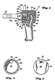
- FIG. 1 The assembled tool and accessory best appear in FIG. 1 as comprising a handle (10) configured here as a "gun” having a main body (12) and associated trigger-equipped grip (14), the two being integrally formed of rigid material such as light-weight steel, aluminum, etc.
- a handle (10) configured here as a "gun” having a main body (12) and associated trigger-equipped grip (14), the two being integrally formed of rigid material such as light-weight steel, aluminum, etc.
- the body is seen as being in the form of a cylinder on a fore-and-aft axis and has having a cylindrical wall (16) opening at its front as a circular rim or edge (18) and defining a cavity (20).
- the accessory may be of any known character and typically includes a barrel (24) having a rear cylindrical part (26) and a fore part such as a chuck (28) for receiving an implement such as a chisel, chipper or the like (not shown).
- a barrel having a rear cylindrical part (26) and a fore part such as a chuck (28) for receiving an implement such as a chisel, chipper or the like (not shown).
- the accessory and handle wall (16) are coaxial.
- the rear part of the barrel is disposed within the handle cavity and retained therein by the shock-absorbent material, in which case the accsessory, or at least its rear portion, is captive in the cavity.
- the arrangement between the handle and accessory is such that the accessory is removably carried by the handle, albeit functioning as an operational part of the handle in working mode.
- the inventive improvement structure resides primarily in the use of a cylindrical insert of hollow member (30) having an outside diameter smaller than the insider diameter of the cylindrical wall (12) so that the insert is receivable within the cavity (20) in such fashion as to provide an annular space (32).
- the insert is of rigid material, such as steel, and is preferably configured as a cup having a rear radial end wall (34) and an annular wall (36) that opens at its front as an annulus or rim (38).
- the outer surface or the cylindrical wall or the insert is provided with several grooves (40) that run angularly of the wall and further grooves (42) that run lengthwise of the wall.
- shock-absorbent material 44
- the material (44) occupies spaces (46) and (48) contiguous with and behind and below the insert, save for a fluid supply tube or conduit (50) embraced by the material (44), which tube is connectable to any typical external power source (not shown).
- the inner part of the tube is connected by a suitable fitting (52) to the rear wall (34) of the cylindrical insert (30), the wall having a thickened rear portion (34) provided with a bore (56) that leads to the interior of the insert for purposes to appear presently.
- the insert is accurately positioned within the cavity so that the insert is coaxial with the cylindrical wall (16) on the foresaid fore-and-aft axis, a procedure that may be accomplished by the use of appropriate jigs, fixtures, etc. (not shown, because of the wide variety of assists that could be employed). Suffice it to say that the properly positioned insert or hollow member (30) becomes a vibration-isolated adjunct to the handle and is retained therein by the shock-absorbent material as explained above. When so positioned, the insert opens forwardly at its annulus or rim (38) in position to receive and form a positive connection with the rear part of the accessory barrel (24).
- the connmection between the barrel and insert is achieved by means securing the two together for operational functioning as a unit.
- the rear part of the barrel and the interior of the insert are of comparable diameters, and the preferred means comprises internal threads (58) within the insert and mating external threads (60) on the rear of the barrel.
- the threads are relatively fine so as to establish a fluid-tight joint between the insert and barrel, since the interior mechanism (not shown) of the barrel is fluid-operated, as is well known to those versed in the art, useful, for example, in reciprocating a chipper, chisel, etc. (not shown) chucked in the barrel fore part.
- Fluid under pressure via the supply conduit or tube (50) and fitting (52) reaches the interior of the barrel via an inlet port(62) at the rear of the barrel (FIG. 3).
- the barrel is tightly screwed into the insert and is prevented from accidental unscrewing by anti-reverse lock means, here provided by the insertion of a removable locking pin (64) through a small radial hole or bore (66) in the barrel rear part (26) and into a registering notch (68) in the insert rim (38), the latter being castellated for the purpose of providing several notches for selective fore-and-aft register with the hole (66) after tightening of the barrel into the insert (30).
- anti-reverse lock means here provided by the insertion of a removable locking pin (64) through a small radial hole or bore (66) in the barrel rear part (26) and into a registering notch (68) in the insert rim (38), the latter being castellated for the purpose of providing several notches for selective fore-and-aft register with the hole (66) after tightening of the barrel into the insert (30).
- the barrel may be easily removed from the handle by removable of the lock pin (64) and unscrewing of the barrel, as for repairs to or replacement of the accessory.
- This is a disctinct advantage over the patented design, since separation of the accessory from the handle becomes important in circumstances just described, besides which manufacture of the handle and insert is facilitated and costs reduced because of the relative case with which the insert may be assembled to the handle.
- the handle, equipeed with the insert (30) may be sold separately for use with existing accessories manufactured to fit the insert.
Landscapes
- Engineering & Computer Science (AREA)
- Mechanical Engineering (AREA)
- Percussive Tools And Related Accessories (AREA)
- Portable Power Tools In General (AREA)
- Vibration Dampers (AREA)
Applications Claiming Priority (2)
| Application Number | Priority Date | Filing Date | Title |
|---|---|---|---|
| US153684 | 1980-05-27 | ||
| US07/153,684 US4771833A (en) | 1988-02-08 | 1988-02-08 | Portable tool with vibration damping |
Publications (2)
| Publication Number | Publication Date |
|---|---|
| EP0327890A2 true EP0327890A2 (de) | 1989-08-16 |
| EP0327890A3 EP0327890A3 (de) | 1991-01-23 |
Family
ID=22548285
Family Applications (1)
| Application Number | Title | Priority Date | Filing Date |
|---|---|---|---|
| EP19890101326 Withdrawn EP0327890A3 (de) | 1988-02-08 | 1989-01-26 | Handwerkzeug mit Vibrationsdämpfung |
Country Status (6)
| Country | Link |
|---|---|
| US (1) | US4771833A (de) |
| EP (1) | EP0327890A3 (de) |
| JP (1) | JPH01281882A (de) |
| KR (1) | KR890012761A (de) |
| CA (1) | CA1298074C (de) |
| DK (1) | DK55689A (de) |
Cited By (1)
| Publication number | Priority date | Publication date | Assignee | Title |
|---|---|---|---|---|
| WO2002098614A1 (en) * | 2001-06-07 | 2002-12-12 | Db Carteggiatura Di Dino Bulian E C. Snc | Element to deaden vibrations |
Families Citing this family (32)
| Publication number | Priority date | Publication date | Assignee | Title |
|---|---|---|---|---|
| PL153240B1 (en) * | 1988-03-29 | 1991-03-29 | Politechnika Poznanska | Vibration damping arrangement for hand tools |
| JP2534318B2 (ja) * | 1988-04-30 | 1996-09-11 | 日立工機株式会社 | 動力工具の防振ハンドル |
| JPH0673826B2 (ja) * | 1988-05-27 | 1994-09-21 | 協和合金株式会社 | 防振ハンドル装置 |
| US4879847A (en) * | 1989-03-13 | 1989-11-14 | Snap-On Tools Corporation | Cover for pneumatic tool |
| US5054562A (en) * | 1990-05-02 | 1991-10-08 | Honsa Ergonomic Technologies, Inc. | Vibration-isolated power tool |
| US5180019A (en) * | 1991-04-15 | 1993-01-19 | Ingersoll-Rand Company | Power tool having selectable inlet location |
| US5697456A (en) * | 1995-04-10 | 1997-12-16 | Milwaukee Electric Tool Corp. | Power tool with vibration isolated handle |
| DE19730356C2 (de) | 1997-07-15 | 2001-05-17 | Wacker Werke Kg | Schwingungsgedämpfter Aufbruch- und/oder Bohrhammer |
| US5860242A (en) * | 1997-09-04 | 1999-01-19 | O'neil; Pat | Removable harmonic tuning system for firearms |
| US6082468A (en) * | 1998-04-20 | 2000-07-04 | Snap-On Tools Company | Interchangeable grips for power hand tools |
| US6308378B1 (en) | 1999-06-01 | 2001-10-30 | Porter-Cable Corporation | Frictional gripping arrangement for a power tool handle |
| DE10162633B4 (de) * | 2001-12-20 | 2012-12-06 | Hilti Aktiengesellschaft | Bolzensetzgerät |
| US6719067B2 (en) * | 2001-12-27 | 2004-04-13 | Taga Corporation | Insert for a plastic power tool housing |
| US6932166B1 (en) * | 2002-12-03 | 2005-08-23 | Paul Kirsch | Pneumatic tool |
| US7478096B2 (en) * | 2003-02-26 | 2009-01-13 | Burnside Acquisition, Llc | History preservation in a computer storage system |
| TWM296773U (en) * | 2006-03-31 | 2006-09-01 | Shuen Tai Prec Entpr Co Ltd | Portable power drill with shock absorption protective sheath |
| US20070246237A1 (en) * | 2006-04-24 | 2007-10-25 | Emile Homsi | Vibration dampening of a power tool |
| DE102006027774A1 (de) * | 2006-06-16 | 2007-12-20 | Robert Bosch Gmbh | Handwerkzeugmaschine |
| TWM303798U (en) * | 2006-06-19 | 2007-01-01 | Shuen Tai Prec Entpr Co Ltd | Handle of lair flux chipper |
| US7401662B2 (en) * | 2006-07-06 | 2008-07-22 | Honsa Ergonomic Technologies, Inc. | Powered hand tool |
| CA493745A (en) * | 2006-10-04 | 1953-06-16 | E. Glassburn William | Bridge-connected relay |
| JP4977533B2 (ja) * | 2007-06-07 | 2012-07-18 | 株式会社マキタ | 可搬型電動工具 |
| SE531283C2 (sv) * | 2007-06-11 | 2009-02-10 | Atlas Copco Tools Ab | Husskarv för ett kraftverktyg |
| WO2009001592A1 (ja) * | 2007-06-25 | 2008-12-31 | Ryobi Ltd. | 電動工具 |
| US7806201B2 (en) * | 2007-07-24 | 2010-10-05 | Makita Corporation | Power tool with dynamic vibration damping |
| US20100064542A1 (en) * | 2008-09-15 | 2010-03-18 | Hamilton Beach Brands, Inc. | Hair drying apparatus |
| JP5395531B2 (ja) * | 2009-06-19 | 2014-01-22 | 株式会社マキタ | 作業工具 |
| US20120097410A1 (en) * | 2010-10-26 | 2012-04-26 | Honsa Thomas W | Tool |
| DE102012103587A1 (de) * | 2012-04-24 | 2013-10-24 | C. & E. Fein Gmbh | Handführbare Werkzeugmaschine mit Außengehäuse |
| US8966773B2 (en) | 2012-07-06 | 2015-03-03 | Techtronic Power Tools Technology Limited | Power tool including an anti-vibration handle |
| EP2969301B1 (de) | 2013-03-12 | 2020-08-12 | Honsa Ergonomic Technologies, Inc. | Endeffektor |
| WO2020252350A1 (en) | 2019-06-12 | 2020-12-17 | Milwaukee Electric Tool Corporation | Rotary power tool |
Family Cites Families (5)
| Publication number | Priority date | Publication date | Assignee | Title |
|---|---|---|---|---|
| US2019964A (en) * | 1933-02-20 | 1935-11-05 | Independent Pneumatic Tool Co | Cushion means for tools |
| US2035643A (en) * | 1934-06-25 | 1936-03-31 | Independent Pneumatic Tool Co | Cushioning means for tools |
| FR867051A (fr) * | 1940-05-28 | 1941-09-26 | Forges & Ateliers De Meudon | Perfectionnement aux outils pneumatiques et autres appareils vibrants |
| US3485307A (en) * | 1968-02-13 | 1969-12-23 | Black & Decker Mfg Co | Portable sonic hand tool with means for reducing the effects of operator bias upon transducer output and efficiency |
| US4648468A (en) * | 1985-06-26 | 1987-03-10 | Honsa Technologies | Portable powered tool with vibration damping |
-
1988
- 1988-02-08 US US07/153,684 patent/US4771833A/en not_active Expired - Lifetime
-
1989
- 1989-01-26 EP EP19890101326 patent/EP0327890A3/de not_active Withdrawn
- 1989-01-31 CA CA000589680A patent/CA1298074C/en not_active Expired - Fee Related
- 1989-02-03 KR KR1019890001273A patent/KR890012761A/ko not_active Withdrawn
- 1989-02-07 DK DK055689A patent/DK55689A/da not_active Application Discontinuation
- 1989-02-08 JP JP1029559A patent/JPH01281882A/ja active Pending
Cited By (1)
| Publication number | Priority date | Publication date | Assignee | Title |
|---|---|---|---|---|
| WO2002098614A1 (en) * | 2001-06-07 | 2002-12-12 | Db Carteggiatura Di Dino Bulian E C. Snc | Element to deaden vibrations |
Also Published As
| Publication number | Publication date |
|---|---|
| KR890012761A (ko) | 1989-09-19 |
| US4771833A (en) | 1988-09-20 |
| DK55689D0 (da) | 1989-02-07 |
| CA1298074C (en) | 1992-03-31 |
| DK55689A (da) | 1989-08-09 |
| EP0327890A3 (de) | 1991-01-23 |
| JPH01281882A (ja) | 1989-11-13 |
Similar Documents
| Publication | Publication Date | Title |
|---|---|---|
| US4771833A (en) | Portable tool with vibration damping | |
| EP1426145B1 (de) | Umkehrbares Bohrantriebswerkzeug | |
| US6354177B2 (en) | 6-in-1 rotary tool | |
| US5379542A (en) | Handgun cleaning tool kit | |
| US5954463A (en) | Reversible drill driver tool | |
| US5470180A (en) | Reversible drill/driver tool | |
| US4899415A (en) | Cleaning rod handle | |
| US4648468A (en) | Portable powered tool with vibration damping | |
| US20100269648A1 (en) | Tool with interchangeable work heads | |
| US5253961A (en) | Coupling for drilling machine with dust extractor | |
| US2714026A (en) | Rotating tool connector | |
| US5427002A (en) | Power drive unit for hand tools | |
| KR20010013577A (ko) | 동력식 손공구용의 상호교환형 파지부 | |
| US20020020973A1 (en) | Workpiece connector for a power tool | |
| AU2024600A (en) | Quick coupler mechanism for power tool bits | |
| EP1955820A1 (de) | Multibit-Antrieb mit Senker für Trockenbauwand | |
| CA2029822A1 (en) | Pneumatic Ground-Piercing Tool | |
| CA2180606A1 (en) | Removable adapter for a power-driven screwdriver | |
| EP4275846A1 (de) | Zubehör für elektrowerkzeug | |
| US5067861A (en) | Tool holder with interchangeable fluid pressure actuated chucks | |
| US5080536A (en) | Boring bar sleeve | |
| US7107874B1 (en) | Hammer having a detachable bell | |
| US3762732A (en) | Clamping device or chuck | |
| US5097555A (en) | Drill bit and screw driver kit | |
| US4490113A (en) | Dental handpiece |
Legal Events
| Date | Code | Title | Description |
|---|---|---|---|
| PUAI | Public reference made under article 153(3) epc to a published international application that has entered the european phase |
Free format text: ORIGINAL CODE: 0009012 |
|
| AK | Designated contracting states |
Kind code of ref document: A2 Designated state(s): DE FR GB IT NL SE |
|
| PUAL | Search report despatched |
Free format text: ORIGINAL CODE: 0009013 |
|
| AK | Designated contracting states |
Kind code of ref document: A3 Designated state(s): DE FR GB IT NL SE |
|
| 17P | Request for examination filed |
Effective date: 19910614 |
|
| 17Q | First examination report despatched |
Effective date: 19920807 |
|
| STAA | Information on the status of an ep patent application or granted ep patent |
Free format text: STATUS: THE APPLICATION IS DEEMED TO BE WITHDRAWN |
|
| 18D | Application deemed to be withdrawn |
Effective date: 19930218 |