EP0328006A2 - Teleskopische Munitionspatrone - Google Patents
Teleskopische Munitionspatrone Download PDFInfo
- Publication number
- EP0328006A2 EP0328006A2 EP89101967A EP89101967A EP0328006A2 EP 0328006 A2 EP0328006 A2 EP 0328006A2 EP 89101967 A EP89101967 A EP 89101967A EP 89101967 A EP89101967 A EP 89101967A EP 0328006 A2 EP0328006 A2 EP 0328006A2
- Authority
- EP
- European Patent Office
- Prior art keywords
- aft
- case
- propellant charge
- projectile
- spring
- Prior art date
- Legal status (The legal status is an assumption and is not a legal conclusion. Google has not performed a legal analysis and makes no representation as to the accuracy of the status listed.)
- Withdrawn
Links
- 239000003380 propellant Substances 0.000 claims abstract description 45
- 238000010304 firing Methods 0.000 claims abstract description 34
- 230000014759 maintenance of location Effects 0.000 claims abstract description 18
- 238000011084 recovery Methods 0.000 claims abstract description 7
- 230000002093 peripheral effect Effects 0.000 claims description 3
- 230000003628 erosive effect Effects 0.000 description 3
- 239000003112 inhibitor Substances 0.000 description 3
- 230000000717 retained effect Effects 0.000 description 3
- 230000003190 augmentative effect Effects 0.000 description 1
- 238000010276 construction Methods 0.000 description 1
- 230000001419 dependent effect Effects 0.000 description 1
- 230000000977 initiatory effect Effects 0.000 description 1
- 239000000463 material Substances 0.000 description 1
- 238000007789 sealing Methods 0.000 description 1
Images
Classifications
-
- F—MECHANICAL ENGINEERING; LIGHTING; HEATING; WEAPONS; BLASTING
- F42—AMMUNITION; BLASTING
- F42B—EXPLOSIVE CHARGES, e.g. FOR BLASTING, FIREWORKS, AMMUNITION
- F42B5/00—Cartridge ammunition, e.g. separately-loaded propellant charges
- F42B5/02—Cartridges, i.e. cases with charge and missile
- F42B5/045—Cartridges, i.e. cases with charge and missile of telescopic type
-
- F—MECHANICAL ENGINEERING; LIGHTING; HEATING; WEAPONS; BLASTING
- F42—AMMUNITION; BLASTING
- F42B—EXPLOSIVE CHARGES, e.g. FOR BLASTING, FIREWORKS, AMMUNITION
- F42B5/00—Cartridge ammunition, e.g. separately-loaded propellant charges
- F42B5/26—Cartridge cases
Definitions
- the present invention generally relates to a cased telescoped ammunition round according to the preamble of claim 1.
- Cased telescoped ammunition is generally well-known. Representative prior art versions of such ammunition are disclosed in US-A-2,866,412, 2,996,988, 4,197,801, 4,220,089, 4,335,657 and 4,604,954.
- a round of cased telescoped ammunition typically includes an elongated cylindrical case defining a chamber that contains a propellant charge.
- the propellant charge has an axial bore through which extends a central tube in coaxial relation with the case and fastened at its opposite ends to the opposite ends of the case.
- a telescoped projectile is housed within a forward portion of the central tube, whereas an aft portion of the central tube, referred to as a control section, receives a piston or spud on the aft end of the projectile.
- a primer is positioned within the control section aft of the projectile spud, and a small amount of propellant is contained therein between the primer and the spud.
- the round of ammunition is loaded in a gun chamber located rearwardly of the gun barrel.
- the primer ignites the small amount of propellant in the control section.
- the resulting gas applies to a force against the spud, driving the projectile forwardly out of the central tube and into the gun barrel.
- the hot gas ignites the main propellant charge surrounding the projectile. Burning of the propellant charge produces gas at much higher pressure which drives the projectile through the gun barrel to exit the muzzle at high velocity.
- the increasing pressure created by the burning propellant charge expands the ammunition case axially and radially.
- the pressure also acts to elastically deform the gun, enlarging the chamber.
- the gun chamber reverts to its unpressurized dimensions.
- the case returns or recovers at least to dimensions which allow clearance between it and the ends and interior surface of the chamber.
- the ammunition cartridge case must expand axially and radially during firing to accommodate the structural response of the gun chamber to gun gas pressure.
- Such cartridge cases are fitted with end caps which seal the chamber to prevent escape of high pressure gun gas.
- the end caps In addition to sealing the chamber during firing, the end caps must be retained by the cylindrical skin tube of the case and must not retard the axial shrinkage of the gun chamber after firing. Retardation would slow the gun and separate of an end cap from the first case of the ammunition round could cause a gun stoppage.
- the present invention provides cased telescoped ammunition designed to achieve the aforementioned objectives.
- the present invention encompasses several different features associated with the end caps and case skin tube of a round of cased telescoped ammunition for augmenting retention and retraction of the end caps. Some of these features are advantageously incorporated together to realize significantly improved results; however, improvement of end cap retention and retraction can be obtained by employment of the features separately from or as alternatives to one another.
- the cased telescoped ammunition round in which the features of the present invention are employed comprises the combination of: (a) an elongated propellant charge having an axial bore therethrough; (b) an elongated tubular case composed of a skin tube and forward and aft end caps on opposite forward and aft ends of the tube, the case defining a chamber that contains the propellant charge; (c) tubular means disposed in the case extending at least partially through the axial bore of the propellant charge from forward and aft ends thereof and attached respectively to the forward and aft end caps of the case; (d) a projectile housed within the tubular means and in the axial bore of the propellant charge; and (e) a primer positioned within the aft end of the tubular means and being actuatable for igniting the propellant charge to cause firing of the projectile forwardly from the case.
- the features of the present invention generally relate to internal spider-like flexure springs having slightly different configurations and being associated with the forward and aft ends of the tubular means adjacent the forward and aft end caps and with the opposite ends of the case skin tube.
- the flexure springs can resiliently and yieldably flex to provide positive end cap retention during cartridge firing and effective end cap retraction after firing to ensure dimensional recovery of the tubular case after firing of the projectile so that the case can be ejected from a gun chamber.
- the spider-like flexure springs have respective peripheral annular ring-like base portions attached by suitable fastening means, such as circumferentially spaced apart rivets, at the interior of the respective forward and aft rims or ends of the case skin tube.
- the springs also have respective pluralities of spring finger portions connected to the respective base portions and projecting radially inwardly therefrom which, at inner tips thereof, are anchored to respective forward and aft ends of the tubular means.
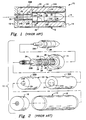
- the ammunition round 10 includes an elongated cylindrical case 12 composed of a pair of forward and aft end seals or caps 14, 16 sealed on opposite ends of a skin tube 18.
- the case 12 defines a chamber 20 that contains a propellant charge 22 composed of forward and aft portions 22A, 22B.
- the propellant charge 22 has an axial bore 24 (composed of corresponding forward and aft portions 24A, 24B) through which extends a center sleeve 26 in coaxial relation with the case 12.
- the center sleeve 26 is fastened at its opposite ends to the end caps 14, 16.
- a tapered or telescoped projectile 28 is housed within a forward end portion 26A of the center sleeve 26.
- the projectile 28 incorporates a short piston or spud 28A of reduced diameter on its aft end which extends in a close fitting relation into the control tube 26B of the center sleeve 26.
- a primer 30 is also positioned within the control tube 26B aft of the projectile spud 28A and a small amount of propellant 32 is contained in the control tube 26B between the primer 30 and the projectile spud 28A.
- Windows or vents 34, 36 are respectively formed through the aft end portion or control tube 26B and the forward end portion 26A of the center sleeve 26.
- the primer 30 is fired initiating the small amount of propellant 32 in the control tube 26B aft of the projectile spud 28A. Expansion of the resulting gas generated by the initiated propellant 32 applies an increasing force against the spud 28A, driving the projectile 28 forward out of the centersleeve 28 and into the rear end of a gun barrel. As the end of the projectile spud 28A moves forward in the control tube 26B of the center sleeve 26, it exposes the vents 34 therein and thereafter the vents 36 in the forward end portion of the center sleeve 26. The hot gas generated by the initiated propellant 32 then ignites the main propellant charge 22 surrounding the projectile 28. Burning of the propellant charge 22 produces gas at much higher pressure which drives the projectile through the gun barrel to exit the muzzle at high velocity.
- the increasing pressure created by the burning propellant charge 22 elongates the case skin tube 18 and forces the end caps 14, 16 apart to the point where they are constrained by the opposite ends of a gun chamber (not shown) which houses the ammunition round 10.
- the pressure also forces the case skin tube 18 radially outward into intimate contact with the cylindrical interior surface of the gun chamber. After intimate contact has been achieved, the pressure continues to increase and act to elastically deform the gun, enlarging the chamber and forcing apart the ends thereof.
- the gun chamber When the pressure is relieved by the exit of the projectile from the muzzle of the barrel, the gun chamber reverts to its unpressurized dimensions.
- the case 12 In order to extract the case 12 from the cylindrical gun chamber, it is necessary that the case 12 returns or recovers at least to dimensions which allow clearance between the end caps 14, 16 of the case 12 and the opposite breech and barrel faces or ends of the chamber as well as radially between the case 12 and interior cylindrical surface of the chamber. It is essential that features be incorporated in the ammunition which will ensure that such dimensional recovery takes place.
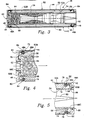
- Figs. 3-5 there are shown the features of the present invention associated with a cased telescoped ammunition round 38 for providing improved end cap retention during firing and end cap retraction after firing to ensure dimensional recovery of the tubular case 40 of the round after firing of a projectile therefrom so that the case can be ejected from the gun chamber.
- the elongated tubular case 40 of the improved round 38 includes a case skin tube 44 and a pair of forward and aft end caps 46, 48 on opposite ends of the tube.
- the tubular case 40 defines a chamber 50 that contains a propellant charge 52 having an axial bore 54.
- Separate forward and aft tubes 56, 58 are disposed in the case 40 extending at least partially through the axial bore 54 of the propellant charge 52 from respective forward and aft ends of the bore.
- the separate forward and aft tubes 56, 58 are attached, such as by being threadably fastened, respectively to the forward and aft end caps 46, 48 of the case 40.
- a projectile 60 spans between and is housed within the separate tubes 56, 58 and within the axial bore 54 of the propellant charge 52.
- a primer 62 along with loose propellant charge 64 are disposed within an aft end of the aft tube 58.
- the primer 62 is actuatable for igniting the loose propellant charge 64 to cause initial propulsion of the projectile 60 forwardly through the aft tube 58.
- the features of the present invention generally relate to internal forward and aft flexure springs 66, 68, each being spider-like in configuration, provided in forward and aft ends of the case 40.
- the flexure springs 66, 68 have slightly different configurations and are associated with the opposite forward and aft rims or ends 70, 72 of the case skin tube 44 and with the forward end of the forward tube 56 and the aft end of the aft tube 58, adjacent respective forward and aft end caps 46, 48.
- the flexure springs 66, 68 are capable of resiliently and yieldably flexing to provide positive end cap retention during firing and effective end cap retraction after firing of the round 38 to ensure dimensional recovery of the tubular case 40 after firing of the projectile 60 so that the case can be readily ejected from the gun chamber.
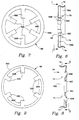
- the forward and aft flexure springs 66, 68 have respective outer peripheral annular ring-like base portions 66A, 68A attached by a plurality of fastening means at the interior of the respective forward and aft ends 70, 72 of the case skin tube 44.
- the springs 66, 68 also have respective pluralities of spring finger portions 66B, 68B connected to the respective base portions 66A, 68A and projecting radially inwardly therefrom which, at inner tips 66C, 68C thereof, are engaged with or anchored to respectively the forward end of the forward tube 56 and the aft end of the aft tube 58.
- the plurality of fastening means are circumferentially spaced about the base portions 66A, 68A of the respective springs 66, 68 and the respective skin tube ends 70, 72 for rigidly attaching the same together.
- the fastening means includes respective forward and aft pluralities of aligned circumferentially spaced holes 74, 76 and 78, 80 formed in the spring base portions 66A, 68A and skin tube ends 70, 72.
- forward and aft pluralities of rivets 82, 84 extend through and fasten the forward and aft spring base portions 66A, 68A and skin tube ends 70, 72 together at the respective pluralities of holes 74, 78 and 76, 80 formed therein.
- each spring 66, 68 and each skin tube end 70, 72 fastened thereto are generally concave-shaped in cross-section such that the skin tube ends seat in the respective spring base portions.
- forward and aft end caps 46, 48 has respective inner annular rims 46A, 48A which overlies the respective seated forward and aft spring base portions 66A, 68A and skin tube ends 70, 72 where the latter are fastened together by the fastening means.
- each spring finger portion 66B of the forward flexure spring 66 is generally linear-shaped in cross-section and its inner tip 66C is snap fitted in a groove 86 formed circumferentially about the exterior of the forward tube 56 to more or less attach or anchor the forward spring 66 to the forward tube 56.
- Each spring finger portion 68A of the aft flexure spring 68 is longer than each spring finger portion 66A of the forward flexure spring 66 and is generally bent inwardly away from the aft end cap 48 and toward aft end of the aft tube 58.
- the aft spring 68 is more or less captured between the aft end cap 48 and aft end of the aft tube 58.
- the internal spider-like flexure springs 66, 68 are attached to respective forward and aft ends 70, 72 of the skin tube 44, detachably anchored to the respective forward end of the forward tube 56 and aft end of the aft tube 58, and disposed adjacent to and internally of respective forward and aft end caps 46, 48 for ensuring retention of the end caps on the skin tube ends during projectile firing.
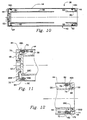
- the springs 66, 68 are resiliently and yieldably flexible for allowing axial movement of the forward and aft end caps 46, 48 and their inner rims 46A, 48a away from the respective forward and aft skin tube ends 70, 72 during projectile firing, to the displaced positions shown in Figs. 10-12.
- Assembly of the round 10 would preferably occur in the following sequence: (1) The primer 62 is installed into the aft tube (control tube) 58. (2) Loose propellant charge 64 and the projectile 60 are installed in the aft tube 58. (3) The aft spring 66 is riveted onto the aft end of the skin tube 44. (4) The aft end cap 48 is slid over the aft skin tube end 72. (5) The aft tube/primer/loose propellant/ projectile subassembly is inserted into the aft end cap/aft spring/skin tube subassembly and threaded into the aft end cap 48.
- the aft propellant charge portion 52B is slid into the skin tube 44 over the aft tube 58, followed by the forward propellant charge portion 52B.
- the forward spring 66 is riveted onto the forward end 70 of the skin tube 44.
- An erosion inhibitor is placed into the bore 54 in the forward propellant charge portion 52A.
- the forward end cap 46 is placed over the forward end 70 of the skin tube 44.
- a tolerance seal 88 is slid onto the forward tube (erosion inhibitor tube) 56.
- the forward tube 56 is inserted into the bore 54 of the forward propellant charge portion 52A and is pushed in until the forward spring finger portions 66B snap into the annular groove 86 in the exterior of the forward tube 56.
- the seams and exit port of the forward end cap 46 are sealed.
Landscapes
- Engineering & Computer Science (AREA)
- General Engineering & Computer Science (AREA)
- Toys (AREA)
- Nozzles (AREA)
- Containers And Packaging Bodies Having A Special Means To Remove Contents (AREA)
Applications Claiming Priority (2)
| Application Number | Priority Date | Filing Date | Title |
|---|---|---|---|
| US154564 | 1988-02-10 | ||
| US07/154,564 US4846069A (en) | 1988-02-10 | 1988-02-10 | Cased telescoped ammunition having features augmenting cartridge case end cap retention and retraction |
Publications (2)
| Publication Number | Publication Date |
|---|---|
| EP0328006A2 true EP0328006A2 (de) | 1989-08-16 |
| EP0328006A3 EP0328006A3 (de) | 1990-01-10 |
Family
ID=22551826
Family Applications (1)
| Application Number | Title | Priority Date | Filing Date |
|---|---|---|---|
| EP89101967A Withdrawn EP0328006A3 (de) | 1988-02-10 | 1989-02-04 | Teleskopische Munitionspatrone |
Country Status (4)
| Country | Link |
|---|---|
| US (1) | US4846069A (de) |
| EP (1) | EP0328006A3 (de) |
| CA (1) | CA1324533C (de) |
| NO (1) | NO890523L (de) |
Cited By (3)
| Publication number | Priority date | Publication date | Assignee | Title |
|---|---|---|---|---|
| EP0475279A1 (de) * | 1990-09-10 | 1992-03-18 | Alliant Techsystems Inc. | Anzündeinlage für die Haupttreibladung einer teleskopischen Munition |
| EP0489283A3 (en) * | 1990-11-14 | 1993-01-20 | Alliant Techsystems Inc. | Forward full caliber control tube for a cased telescoped ammunition round |
| GB2287775A (en) * | 1994-03-15 | 1995-09-27 | Royal Ordnance Plc | Ammunition cartridge cases |
Families Citing this family (7)
| Publication number | Priority date | Publication date | Assignee | Title |
|---|---|---|---|---|
| US5072647A (en) * | 1989-02-10 | 1991-12-17 | Gt-Devices | High-pressure having plasma flow transverse to plasma discharge particularly for projectile acceleration |
| US5147978A (en) * | 1990-09-10 | 1992-09-15 | Alliant Techsystems Inc. | Main propellant ignition liner for cased telescoped ammunition |
| US5042388A (en) * | 1990-11-14 | 1991-08-27 | Alliant Techsystems Inc. | Forward control tube with sequenced ignition |
| US6497709B1 (en) | 1992-03-31 | 2002-12-24 | Boston Scientific Corporation | Metal medical device |
| US5630840A (en) | 1993-01-19 | 1997-05-20 | Schneider (Usa) Inc | Clad composite stent |
| AUPS303702A0 (en) | 2002-06-20 | 2002-07-11 | Metal Storm Limited | A cartridge assembly for multiple projectiles |
| US20090308274A1 (en) * | 2008-06-11 | 2009-12-17 | Lockheed Martin Corporation | Integrated Pusher Plate for a Canister- or Gun-Launched Projectile and System Incorporating Same |
Family Cites Families (33)
| Publication number | Priority date | Publication date | Assignee | Title |
|---|---|---|---|---|
| US331511A (en) * | 1885-12-01 | Wilhelm lorenz | ||
| US300449A (en) * | 1884-06-17 | Cartridge-shell | ||
| US546936A (en) * | 1892-04-16 | 1895-09-24 | James Pinfold | Cartridge case |
| US702208A (en) * | 1902-02-25 | 1902-06-10 | William Everton Hayner | Cartridge. |
| US1062604A (en) * | 1911-10-21 | 1913-05-27 | John D Pedersen | Gun-operating cartridge. |
| US1079083A (en) * | 1913-03-27 | 1913-11-18 | Joseph H Wesson | Cartridge. |
| US1094565A (en) * | 1913-11-19 | 1914-04-28 | Union Metallic Cartridge Co | Cartridge. |
| DE594607C (de) * | 1933-01-18 | 1934-03-19 | Asturienne Mines Comp Royale | Aus einem Stueck gezogene Patronenhuelse |
| FR764951A (fr) * | 1933-09-21 | 1934-05-31 | Rheinische Metallw & Maschf | Douille de cartouche |
| US2349970A (en) * | 1939-05-26 | 1944-05-30 | Lambeek Adriaan Jan Jurriaan | Cartridge case |
| US2330200A (en) * | 1940-11-29 | 1943-09-28 | Ernest C Bomar | Cartridge case |
| US2402068A (en) * | 1944-01-14 | 1946-06-11 | Remington Arms Co Inc | Ammunition |
| GB587478A (en) * | 1944-03-29 | 1947-04-28 | Charles Dennistoun Burney | Improvements in or relating to ammunition cartridges |
| US2568080A (en) * | 1946-10-25 | 1951-09-18 | Gene C Holmes | Cartridge |
| US2853945A (en) * | 1955-04-06 | 1958-09-30 | Boehm Pressed Steel Company | Two piece cartridge and method of making same |
| FR1137912A (fr) * | 1955-11-22 | 1957-06-05 | Forges Ateliers Const Electr | Douilles perfectionnées en tôle enroulée |
| US2938458A (en) * | 1956-02-16 | 1960-05-31 | John F O'brien | Obturating cartridge |
| US2866412A (en) * | 1956-03-14 | 1958-12-30 | Arthur R Meyer | Cylindrical obturating cartridge |
| US2996988A (en) * | 1958-03-04 | 1961-08-22 | Hughes Tool Company Aircraft D | Cartridge for firearms having sideloaded firing chambers |
| US3009394A (en) * | 1960-07-12 | 1961-11-21 | Ewald A Kamp | Ammunition link |
| DE1283122B (de) * | 1964-01-08 | 1968-11-14 | Dynamit Nobel Ag | Mit Haftreibung zwischen Patrone und Geschossbohrung einzusetzende Abschusspatrone fuer Granatwerfer |
| US3568599A (en) * | 1967-09-01 | 1971-03-09 | Trw Inc | Ammunition improvements to permit firing of a conventional closed chamber cartridge in an open chamber breech mechanism |
| US3590740A (en) * | 1968-11-12 | 1971-07-06 | Herter Inc S | Plastic shot shell and base wad |
| US3761322A (en) * | 1970-12-28 | 1973-09-25 | Olin Mathieson | Method of preparing aluminum cartridge case |
| US4000697A (en) * | 1972-08-10 | 1977-01-04 | The United States Of America As Represented By The Secretary Of The Air Force | Mechanical retention system for use with caseless ammunition |
| DE2307907C2 (de) * | 1973-02-17 | 1983-09-01 | Rheinmetall GmbH, 4000 Düsseldorf | Treibladungshülse |
| DE2705278C2 (de) * | 1977-02-09 | 1984-02-23 | Rheinmetall GmbH, 4000 Düsseldorf | Stummelhülse mit Liderung |
| US4197801A (en) * | 1978-04-07 | 1980-04-15 | Ford Aerospace & Communications Corporation | Ammunition round |
| US4220089A (en) * | 1978-07-24 | 1980-09-02 | The United States Of America As Represented By The Secretary Of The Army | Cartridge for a fully telescoped projectile |
| US4335657A (en) * | 1980-08-13 | 1982-06-22 | Ford Aerospace & Communications Corp. | Ammunition round with retained piston |
| DE8326013U1 (de) * | 1983-09-10 | 1986-06-26 | Rheinmetall GmbH, 4000 Düsseldorf | Treibladungshülse |
| US4604954A (en) * | 1984-10-22 | 1986-08-12 | Ford Aerospace & Communications Corp. | Telescoped ammunition with dual split cartridge case |
| US4691638A (en) * | 1985-04-30 | 1987-09-08 | Honeywell Inc. | Cased telescoped ammunition |
-
1988
- 1988-02-10 US US07/154,564 patent/US4846069A/en not_active Expired - Fee Related
-
1989
- 1989-02-04 EP EP89101967A patent/EP0328006A3/de not_active Withdrawn
- 1989-02-08 NO NO89890523A patent/NO890523L/no unknown
- 1989-02-09 CA CA000590539A patent/CA1324533C/en not_active Expired - Fee Related
Cited By (3)
| Publication number | Priority date | Publication date | Assignee | Title |
|---|---|---|---|---|
| EP0475279A1 (de) * | 1990-09-10 | 1992-03-18 | Alliant Techsystems Inc. | Anzündeinlage für die Haupttreibladung einer teleskopischen Munition |
| EP0489283A3 (en) * | 1990-11-14 | 1993-01-20 | Alliant Techsystems Inc. | Forward full caliber control tube for a cased telescoped ammunition round |
| GB2287775A (en) * | 1994-03-15 | 1995-09-27 | Royal Ordnance Plc | Ammunition cartridge cases |
Also Published As
| Publication number | Publication date |
|---|---|
| US4846069A (en) | 1989-07-11 |
| NO890523L (no) | 1989-08-11 |
| CA1324533C (en) | 1993-11-23 |
| NO890523D0 (no) | 1989-02-08 |
| EP0328006A3 (de) | 1990-01-10 |
Similar Documents
| Publication | Publication Date | Title |
|---|---|---|
| US4907510A (en) | Cased telescoped ammunition having features augmenting cartridge case dimensional recovery by center sleeve | |
| US4802415A (en) | Telescoped ammunition round having subcaliber projectile sabot with integral piston | |
| KR100628599B1 (ko) | 축방향으로적층된탄환을구비한총신조립체 | |
| US4604954A (en) | Telescoped ammunition with dual split cartridge case | |
| JP4111465B2 (ja) | 火器 | |
| US4335657A (en) | Ammunition round with retained piston | |
| US4938145A (en) | Cased telescoped ammunition having features augmenting cartridge case dimensional recovery by case skin tube | |
| US4958567A (en) | Training cartridge with improved case for fixing propellant position in powder chamber | |
| US3919799A (en) | Grenade launcher and annular cartridge therefor | |
| US4846069A (en) | Cased telescoped ammunition having features augmenting cartridge case end cap retention and retraction | |
| US4782758A (en) | Ammunition round | |
| US3477374A (en) | Fixed primer set-back cartridge | |
| US4691638A (en) | Cased telescoped ammunition | |
| CA2343968C (en) | Blank cartridge for self loading guns | |
| US20100043628A1 (en) | Projectile for a Stacked Projectile Weapon | |
| US5173571A (en) | Projectile guide for telescoped ammunition | |
| US3326128A (en) | Rockets and combinations of rockets and cases | |
| EP3341676B1 (de) | Patronenmunition | |
| US6367387B1 (en) | Low-calibre shot gun bullet, especially for shot guns with a partially or fully distended barrel | |
| US5069137A (en) | Cased telescoped ammunition round | |
| EP0459209B1 (de) | Patronierte Munition in Teleskopanordnung | |
| US3289584A (en) | Mortar ammunition | |
| US5969289A (en) | Subcaliber projectile | |
| US4104969A (en) | Arrangement for improving the burning efficiency of a rocket-borne solid propellant charge cartridge | |
| AU676095B2 (en) | Recoil reducer wad for shotgun ammunition |
Legal Events
| Date | Code | Title | Description |
|---|---|---|---|
| PUAI | Public reference made under article 153(3) epc to a published international application that has entered the european phase |
Free format text: ORIGINAL CODE: 0009012 |
|
| AK | Designated contracting states |
Kind code of ref document: A2 Designated state(s): CH DE FR GB IT LI NL |
|
| PUAL | Search report despatched |
Free format text: ORIGINAL CODE: 0009013 |
|
| AK | Designated contracting states |
Kind code of ref document: A3 Designated state(s): CH DE FR GB IT LI NL |
|
| 17P | Request for examination filed |
Effective date: 19900626 |
|
| 17Q | First examination report despatched |
Effective date: 19911007 |
|
| RAP1 | Party data changed (applicant data changed or rights of an application transferred) |
Owner name: ALLIANT TECHSYSTEMS INC. |
|
| STAA | Information on the status of an ep patent application or granted ep patent |
Free format text: STATUS: THE APPLICATION HAS BEEN WITHDRAWN |
|
| 18W | Application withdrawn |
Withdrawal date: 19930120 |