EP0328015A2 - Cartouche du type télescopique pour munitions - Google Patents
Cartouche du type télescopique pour munitions Download PDFInfo
- Publication number
- EP0328015A2 EP0328015A2 EP89101984A EP89101984A EP0328015A2 EP 0328015 A2 EP0328015 A2 EP 0328015A2 EP 89101984 A EP89101984 A EP 89101984A EP 89101984 A EP89101984 A EP 89101984A EP 0328015 A2 EP0328015 A2 EP 0328015A2
- Authority
- EP
- European Patent Office
- Prior art keywords
- case
- sleeve
- center sleeve
- propellant charge
- ammunition round
- Prior art date
- Legal status (The legal status is an assumption and is not a legal conclusion. Google has not performed a legal analysis and makes no representation as to the accuracy of the status listed.)
- Withdrawn
Links
Images
Classifications
-
- F—MECHANICAL ENGINEERING; LIGHTING; HEATING; WEAPONS; BLASTING
- F42—AMMUNITION; BLASTING
- F42B—EXPLOSIVE CHARGES, e.g. FOR BLASTING, FIREWORKS, AMMUNITION
- F42B5/00—Cartridge ammunition, e.g. separately-loaded propellant charges
- F42B5/02—Cartridges, i.e. cases with charge and missile
- F42B5/045—Cartridges, i.e. cases with charge and missile of telescopic type
Definitions
- the present invention generally relates to a cased telescoped ammunition round according to the preamble of claim 1, 2 or 7.
- Cased telescoped ammunition is generally well-known. Representative prior art versions of such ammunition are disclosed in US-A-2 866 412, 2 996 988, 4 197 801, 4 220 089, 4 335 657 and 4 604 954.
- a round of cased telescoped ammunition includes an elongated cylindrical case defining a chamber that contains a propellant charge.
- the propellant charge has an axial bore through which extends a center sleeve in coaxial relation with the case and fastened at its opposite ends to the opposite ends of the case.
- a telescoped projectile is housed within a forward portion of the center sleeve, whereas an aft portion of the center sleeve, referred to as a control tube, receives a piston or spud on the aft end of the projectile.
- a primer is positioned within the control tube aft of the projectile spud, and a small amount of propellant is contained therein between the primer and the spud.
- the round of ammunition is loaded in a gun chamber located rearwardly of the gun barrel.
- the primer ignites the small amount of propellant in the control tube.
- the resulting gas applies a force against the spud, driving the projectile forwardly out of the center sleeve and into the gun barrel.
- the hot gas ignites the main propellant charge surrounding the projectile. Burning of the propellant charge produces gas at much higher pressure which drives the projectile through the gun barrel to exit the muzzle at high velocity.
- the increasing pressure created by the burning propellant charge expands the ammunition case axially and radially. Expansion of the case is constrained by the opposite ends and cylindrical interior surface of the gun chamber housing the ammunition round. The pressure also acts to elastically deform the gun, enlarging the chamber. Then, when the pressure is relieved by exit of the projectile from the gun barrel, the gun chamber reverts to its unpressurized dimensions. In order to extract the case from the gun chamber, it is necessary that the case return or recover at least to dimensions which allow clearance between it and the ends and interior surface of the chamber.
- one step taken is to split longitudinally the skin tube of the cartridge case to relieve any pressure between the yielded skin tube and the recovered chamber diameter.
- the end caps are free to move relative to the split skin tube and require special measures to maintain some connection between the end caps and split skin tube.
- the special measures required to connect the end caps and tube skin make for unreliable cartridge case integrity, particularly after firing. Also, splitting of the skin tube allows undesirable contamination of the gun chamber to occur during firing of the round.
- the present invention provides cased telescoped ammunition designed to satisfy the aforementioned needs.
- the present invention encompasses several different features associated with the center sleeve of a round of cased telescope ammunition for augmenting cartridge case dimensional recovery by the center sleeve. Some of these features are advantageously incorporated together to realize significantly improved cartridge case dimensional recovery; however, improvement of dimensional recovery can be obtained by employment of certain of the features separately from or as alternatives to certain of the others.
- the cased telescoped ammunition round in which the features of the present invention are employed comprises the combination of: (a) an elongated propellant charge having an axial bore therethrough; (b) an elongated tubular case having opposite ends and defining a chamber that contains the propellant charge; (c) a center sleeve disposed in the case through the axial bore of the propellant charge and attached at its opposite ends to the opposite ends of the case; (d) a projectile housed within a forward portion of the center sleeve; and (e) a primer positioned within an aft portion of the center sleeve and being actuatable for igniting the propellant charge for causing firing of the projectile forwardly from the center sleeve and the case.
- One feature relates to the provision of an elastic center sleeve in the round designed to resiliently stretch in response to high internal pressures created by burning of the propellant charge for firing of the projectile and then to return or contract to its original dimensions in response to relief of the pressure. More particularly, by selection of the proper material for the center sleeve, it can be designed such that upon firing of the round the longitudinal stress encountered by the sleeve will uniformly exceed the yield stress of its material. As a result of the material selected and the particular sleeve design, the sleeve will shorten on relief of the internal pressure by an amount equal to the ratio of the yield stress or strength to the modulus of elasticity for the particular material times the free length of the sleeve.
- Another feature is directed to the use of a plurality of longitudinal structural members.
- the structural members are provided so as to extend between and fasten to opposite ends of the case Also, the structural members are spaced circumferentially about and between the center sleeve and the case of the round.
- Still another feature concerns the use of spring means formed integral with the center sleeve for augmenting its recovery.
- a portion of the center sleeve at the merger of its forward and aft portions is arcuately configured in a direction which resiliently resists elongation of the center sleeve.
- Yet another feature relates to the use of spring means which is provided as a component separate from the center sleeve for augmenting its recovery.
- the center sleeve can be separated into forward and aft portions which are coupled together by the spring component.
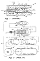
- the ammunition round 10 includes an elongated cylindrical case 12 composed of a pair of forward and aft end seals or caps 14, 16 sealed on opposite ends of a skin tube 18.
- the case 12 defines a chamber 20 that contains a propellant charge 22 composed of forward and aft portions 22A, 22B.
- the propellant charge 22 has an axial bore 24 (composed of corresponding forward and aft portions 24A, 24B) through which extends a center sleeve in coaxial relation with the case 12.
- the center sleeve 26 is fastened at its opposite ends to the end caps 14, 16.
- a projectile 28 is housed within a forward end portion 26A of the center sleeve 26.
- the projectile 28 incorporates a short piston or spud 28A of reduced diameter on its aft end which extends in a close fitting relation into the control tube 26B of the center sleeve 26.
- a primer 30 is also positioned within the control tube 26B aft of the projectile spud 28A and a small amount of propellant 32 is contained in the control sleeve 26B between the primer 30 and the projectile spud 28A.
- Windows or vents 34, 36 are respectively formed through the aft end portion or control tube 26B and the forward end portion 26A of the center sleeve 26.
- the primer 30 is fired initiating the small amount of propellant 32 in the control tube 26B aft of the projectile spud 28A. Expansion of the resulting gas generated by the initiated propellant 32 applies an increasing force against the spud 28A, driving the projectile 28 forward out of the center sleeve 28 and into the rear end of a gun barrel. As the end of the projectile spud 28A moves forward in the control tube 26B of the center sleeve 26, it exposes the vents 34 therein and thereafter the vents 36 in the forward end portion of the center sleeve 26. The hot gas generated by the initiated propellant 32 then ignites the main propellant charge 22 surrounding the projectile 28. Burning of the propellant charge 22 produces gas at much higher pressure which drives the projectile through the gun barrel to exit the muzzle at high velocity.
- the increasing pressure created by the burning propellant charge 22 elongates the case skin tube 18 and forces the end caps 14, 16 apart to the point where they are constrained by the opposite ends of a gun chamber (not shown) which houses the ammunition round 10.
- the pressure also forces the case skin tube 18 radially outward into intimate contact with the cylindrical interior surface of the gun chamber. After intimate contact has been achieved, the pressure continues to increase and acts to elastically deform the gun, enlarging the chamber and forcing apart the ends thereof.
- the gun chamber When the pressure is relieved by the exit of the projectile from the muzzle of the barrel, the gun chamber reverts to its unpressurized dimensions.
- the case 12 In order to extract the case 12 from the cylindrical gun chamber, it is necessary that the case 12 return or recover at least to dimensions which allow clearance between the end caps 14, 16 of the case 12 and the opposite breech and barrel faces or ends of the chamber as well as radially between the case 12 and interior cylindrical surface of the chamber. It is essential that features be incorporated in the ammunition which will ensure that such dimensional recovery takes place.
- One feature of the present invention relates to the design of sufficient elasticity into the center sleeve 26 to make dimensional recovery possible.
- the center sleeve 26 of the round 10 is designed to resiliently stretch in response to high internal pressures created by burning of the propellant charge 22 for firing of the projectile 28 and then to return or contract to its original dimensions in response to relief of the pressure.
- the proper material for the center sleeve 26 it can be designed such that upon firing of the round 10 the longitudinal stress encountered by the sleeve 26 will uniformly exceed the yield stress of its material.
- the sleeve 26 will shorten on relief of the internal pressure by an amount equal to the ratio of the yield stress or strength to the modulus of elasticity for the particular material times the free length of the sleeve 26.
- the material used to fabricate the sleeve 26 can be stainless steel.
- the material of the sleeve 26 will need to be thicker in the regions thereof adjacent the vents than other uninterrupted regions thereof so that the total quantity of material will the same in any axial cross section of the sleeve 26.
- the center sleeve 26 so designed provides a solid means to connect and maintain the position of the end caps 14, 16 which allows the case skin tube 18 to be split, if desired, without destroying the integrity of the cartridge case 12.
- the design of some guns may be such that elastic deformation of the gun chamber (lengthwise from its breech face to barrel face) may exceed the dimensional recovery achievable by the center sleeve alone.
- various other features of the present invention can be used to respectively augment the recovery provided by the elastic sleeve or to accomplish such recovery by themselves. In such manner, ejection of the fired cartridge case from the gun chamber is facilitated.
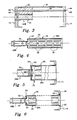
- Fig. 3 there is shown another feature of the present invention whose purpose is to augment dimensional recovery of the cartridge case 12 brought about by the center sleeve 26 or the achievement of such recovery by the provision of this feature alone.
- the feature is directed to the use of a plurality of elongated longitudinal structural members 38 (only one of which is illustrated in Fig. 3).
- the structural members 38 preferably in the form of long metal screws, extend between and fasten to forward and aft end caps 14, 16 of the case 12.
- the structural member 38 has a grooved head 40 at one end and threads 42 at an opposite end.
- a threaded hole 44 is tapped through the forward end cap 14 to receive the threads 42 of the member 38, whereas the head 40 of the member seats in a countersunk hole 46 in the aft end cap 16.
- the structural members 38 are circumferentially spaced about and between the center sleeve 26 and the case 12.
- a plurality of elongated bores 48 are correspondingly formed longitudinally through the propellant charge 22 to receive the plurality of members 38.
- the forward end portion 26A of the center sleeve 26 need not be provided in the round 10. Only the control tube 26B of the center sleeve 26 needs to be employed in the round.
- the control tube 26B will function to hold the primer 30, the spud 28A of the projectile 28 and the quantity of propellant 32, to provide for delay in ignition of the propellant charge 22, and to assist in guiding the fired projectile into the gun barrel.
- Fig. 4 there is shown still another feature of the present invention whose purpose is the same as that of the structural members 38 -- to augment dimensional recovery of the cartridge case 12 brought about by the center sleeve 26 or the achievement of such recovery by the provision of this feature alone.
- the feature concerns spring means formed integral with the center sleeve 26 for augmenting its recovery.
- an integral intermediate portion of the center sleeve 26 located at the merger of its forward and aft portions 26A, 26B is arcuately configured as an annular disk-like spring element 50.
- the spring element 50 is disposed in transverse relation to the longitudinal axis A of the case 12 and the center tube 26.
- the spring element 50 is concave-shaped in a direction extending axially toward the forward end cap 14 of the case 12 so that it will resiliently resist elongation of the center sleeve 26.
- the spring element 50 thus acts as a belleville spring being resiliently yieldable to permit necessary elongation of the sleeve 26.
- the resilient nature of the spring element 50 ensures sufficient retraction the end caps 14, 16 of the case 12 toward one another after firing of the projectile 22 to achieve ejection of the cartridge case 12 from the gun chamber.
- Figs. 5 and 6 there is shown yet another feature of the present invention whose purpose is the same as that mentioned above.
- the feature is directed to spring means which is provided as a component separate from but connected to the center sleeve 26 for augmenting its recovery.
- the center sleeve 26 is separated into its forward and aft portions 26A, 26B.
- the forward and aft sleeve portions 26A, 26B are then coupled together by the separate spring component.
- the spring component is in the form of a annular disk-like spring element 52 generally similar in configuration and location to the integral spring element 50 in Fig. 4.
- the forward and aft portions 26A, 26B of the center tube 26 have respective internal peripheral groove 54 and notches 56 formed therein for gripping the spring element 52 at respective inner and outer peripheries thereof located at adjacent ends thereof.
- the spring component is in the form of a pair of annular washer-like spring elements 58.
- Each spring element 58 has a circumferential configuration which is wavy or undulating in the direction of the axis A of the sleeve 26.
- the spring elements 58 are disposed respectively at the adjacent ends of the forward and aft portions 26A, 26B of the center sleeve 26 and at the connection between the forward end cap 14 and an outwardly-turned flange 60 on the forward end of the center sleeve 26.
- the adjacent ends of the forward and aft center sleeve portions 26A, 26B have respective inwardly-turned and outwardly-turned flanges 62, 64 which extend in transverse relation to the axis A.
- One of the spring elements 58 is captured between the flanges 64, 62 maintaining them in axially spaced relation with respect to one another.
- An annular recess 66 is defined in the external side of the forward end cap 14.
- the other spring element 58 is seated therein, captured between the forward end cap 14 and the outwardly-turned flange 60 on the forward end of the center sleeve 26.
- the flange 60 is spaced forwardly of the bottom of the recess 66 by the other spring element 58.
- the spring elements 58 are composed of metal and are resiliently yieldable for permitting axial elongation of the center sleeve 26 while ensuring recovery thereof.
Landscapes
- Engineering & Computer Science (AREA)
- General Engineering & Computer Science (AREA)
- Toys (AREA)
- Portable Nailing Machines And Staplers (AREA)
Applications Claiming Priority (2)
| Application Number | Priority Date | Filing Date | Title |
|---|---|---|---|
| US154416 | 1988-02-10 | ||
| US07/154,416 US4907510A (en) | 1988-02-10 | 1988-02-10 | Cased telescoped ammunition having features augmenting cartridge case dimensional recovery by center sleeve |
Publications (2)
| Publication Number | Publication Date |
|---|---|
| EP0328015A2 true EP0328015A2 (fr) | 1989-08-16 |
| EP0328015A3 EP0328015A3 (fr) | 1990-01-10 |
Family
ID=22551279
Family Applications (1)
| Application Number | Title | Priority Date | Filing Date |
|---|---|---|---|
| EP89101984A Withdrawn EP0328015A3 (fr) | 1988-02-10 | 1989-02-04 | Cartouche du type télescopique pour munitions |
Country Status (3)
| Country | Link |
|---|---|
| US (2) | US4907510A (fr) |
| EP (1) | EP0328015A3 (fr) |
| NO (1) | NO885677L (fr) |
Cited By (4)
| Publication number | Priority date | Publication date | Assignee | Title |
|---|---|---|---|---|
| WO1991011675A3 (fr) * | 1990-02-02 | 1991-09-19 | Honeywell Inc | Douille pour cartouche telescopique |
| EP0459209A1 (fr) * | 1990-05-17 | 1991-12-04 | Alliant Techsystems Inc. | Munition à cartouche du type télescopique |
| EP0459207A1 (fr) * | 1990-05-17 | 1991-12-04 | Alliant Techsystems Inc. | Munition à cartouche du type télescopique |
| CN112129167A (zh) * | 2020-09-24 | 2020-12-25 | 哈尔滨工业大学 | 一种小型回转体旋转发射装置 |
Families Citing this family (21)
| Publication number | Priority date | Publication date | Assignee | Title |
|---|---|---|---|---|
| US4907510A (en) * | 1988-02-10 | 1990-03-13 | Honeywell Inc. | Cased telescoped ammunition having features augmenting cartridge case dimensional recovery by center sleeve |
| US6748870B2 (en) | 2001-10-22 | 2004-06-15 | Armtec Defense Products Company | Ammunition round assembly with combustible cartridge case |
| US6901866B2 (en) | 2001-11-27 | 2005-06-07 | Armtec Defense Products Company | Combustible cased telescoped ammunition assembly |
| US6575097B1 (en) * | 2002-07-29 | 2003-06-10 | The United States Of America As Represented By The Secretary Of The Army | Large caliber case telescoped ammunition |
| US6688233B1 (en) * | 2002-09-24 | 2004-02-10 | The United States Of America As Represented By The Secretary Of The Army | System and method for effecting mechanical translation of projectiles in cased telescoped ammunition using smart material |
| US7032492B2 (en) * | 2003-09-11 | 2006-04-25 | Milton S. Meshirer | Ammunition articles comprising light-curable moisture-preventative sealant and method of manufacturing same |
| US7363861B2 (en) * | 2004-08-13 | 2008-04-29 | Armtec Defense Products Co. | Pyrotechnic systems and associated methods |
| US7610858B2 (en) * | 2005-12-27 | 2009-11-03 | Chung Sengshiu | Lightweight polymer cased ammunition |
| US8146502B2 (en) | 2006-01-06 | 2012-04-03 | Armtec Defense Products Co. | Combustible cartridge cased ammunition assembly |
| US20100274544A1 (en) * | 2006-03-08 | 2010-10-28 | Armtec Defense Products Co. | Squib simulator |
| US7913625B2 (en) * | 2006-04-07 | 2011-03-29 | Armtec Defense Products Co. | Ammunition assembly with alternate load path |
| US8141492B1 (en) * | 2008-05-15 | 2012-03-27 | Jonathan G. Ambs | Insulated secondary charges |
| US9810512B2 (en) * | 2012-02-07 | 2017-11-07 | Nikolay Nikolaevich Kireev | Special cartridge (variants) |
| US11668549B2 (en) | 2012-09-28 | 2023-06-06 | Federal Cartridge Company | Muzzleloader systems |
| US10605577B2 (en) | 2012-09-28 | 2020-03-31 | Vista Outdoor Operations Llc | Muzzleloader systems |
| US9329003B2 (en) | 2012-09-28 | 2016-05-03 | Vista Outdoor Operations Llc | Muzzleloader systems |
| US9146086B2 (en) | 2012-09-28 | 2015-09-29 | Vista Outdoor Operations Llc | Muzzleloader bullet system |
| US10030956B2 (en) | 2012-09-28 | 2018-07-24 | Vista Outdoor Operations Llc | Muzzleloader systems |
| US20170328690A1 (en) * | 2016-05-11 | 2017-11-16 | U.S. Government As Represented By The Secretary Of The Army | Lightweight Cartridge Case and Weapon System |
| USD849874S1 (en) | 2018-01-21 | 2019-05-28 | Vista Outdoor Operations Llc | Muzzleloader propellant cartridge |
| US11041701B1 (en) * | 2019-07-03 | 2021-06-22 | The United States Of America As Represented By The Secretary Of The Army | Combustible munition case with cell cavities |
Family Cites Families (36)
| Publication number | Priority date | Publication date | Assignee | Title |
|---|---|---|---|---|
| US300449A (en) * | 1884-06-17 | Cartridge-shell | ||
| US331511A (en) * | 1885-12-01 | Wilhelm lorenz | ||
| US546936A (en) * | 1892-04-16 | 1895-09-24 | James Pinfold | Cartridge case |
| US702208A (en) * | 1902-02-25 | 1902-06-10 | William Everton Hayner | Cartridge. |
| US1062604A (en) * | 1911-10-21 | 1913-05-27 | John D Pedersen | Gun-operating cartridge. |
| US1079083A (en) * | 1913-03-27 | 1913-11-18 | Joseph H Wesson | Cartridge. |
| US1094565A (en) * | 1913-11-19 | 1914-04-28 | Union Metallic Cartridge Co | Cartridge. |
| GB400801A (en) * | 1933-01-07 | 1933-11-02 | Alfred Dhome | Improvements in or relating to metal cartridge cases |
| DE594607C (de) * | 1933-01-18 | 1934-03-19 | Asturienne Mines Comp Royale | Aus einem Stueck gezogene Patronenhuelse |
| US2349970A (en) * | 1939-05-26 | 1944-05-30 | Lambeek Adriaan Jan Jurriaan | Cartridge case |
| US2362738A (en) * | 1941-02-10 | 1944-11-14 | Vera E Yarbrough | Cartridge |
| US2402068A (en) * | 1944-01-14 | 1946-06-11 | Remington Arms Co Inc | Ammunition |
| GB587478A (en) * | 1944-03-29 | 1947-04-28 | Charles Dennistoun Burney | Improvements in or relating to ammunition cartridges |
| US2568080A (en) * | 1946-10-25 | 1951-09-18 | Gene C Holmes | Cartridge |
| US2853945A (en) * | 1955-04-06 | 1958-09-30 | Boehm Pressed Steel Company | Two piece cartridge and method of making same |
| FR1137912A (fr) * | 1955-11-22 | 1957-06-05 | Forges Ateliers Const Electr | Douilles perfectionnées en tôle enroulée |
| US2938458A (en) * | 1956-02-16 | 1960-05-31 | John F O'brien | Obturating cartridge |
| US2866412A (en) * | 1956-03-14 | 1958-12-30 | Arthur R Meyer | Cylindrical obturating cartridge |
| US2990684A (en) * | 1958-02-10 | 1961-07-04 | Cohen William | Rod assembled plastic rocket |
| US2996988A (en) * | 1958-03-04 | 1961-08-22 | Hughes Tool Company Aircraft D | Cartridge for firearms having sideloaded firing chambers |
| FR1571251A (fr) * | 1958-11-07 | 1969-06-20 | ||
| DE1283122B (de) * | 1964-01-08 | 1968-11-14 | Dynamit Nobel Ag | Mit Haftreibung zwischen Patrone und Geschossbohrung einzusetzende Abschusspatrone fuer Granatwerfer |
| US3568599A (en) * | 1967-09-01 | 1971-03-09 | Trw Inc | Ammunition improvements to permit firing of a conventional closed chamber cartridge in an open chamber breech mechanism |
| US3590740A (en) * | 1968-11-12 | 1971-07-06 | Herter Inc S | Plastic shot shell and base wad |
| US3761322A (en) * | 1970-12-28 | 1973-09-25 | Olin Mathieson | Method of preparing aluminum cartridge case |
| US4000697A (en) * | 1972-08-10 | 1977-01-04 | The United States Of America As Represented By The Secretary Of The Air Force | Mechanical retention system for use with caseless ammunition |
| DE2307907C2 (de) * | 1973-02-17 | 1983-09-01 | Rheinmetall GmbH, 4000 Düsseldorf | Treibladungshülse |
| US3892181A (en) * | 1973-03-26 | 1975-07-01 | Summa Corp | Flat telescoped cartridge casing |
| DE2705278C2 (de) * | 1977-02-09 | 1984-02-23 | Rheinmetall GmbH, 4000 Düsseldorf | Stummelhülse mit Liderung |
| US4197801A (en) * | 1978-04-07 | 1980-04-15 | Ford Aerospace & Communications Corporation | Ammunition round |
| US4220089A (en) * | 1978-07-24 | 1980-09-02 | The United States Of America As Represented By The Secretary Of The Army | Cartridge for a fully telescoped projectile |
| US4335657A (en) * | 1980-08-13 | 1982-06-22 | Ford Aerospace & Communications Corp. | Ammunition round with retained piston |
| US4604954A (en) * | 1984-10-22 | 1986-08-12 | Ford Aerospace & Communications Corp. | Telescoped ammunition with dual split cartridge case |
| US4681038A (en) * | 1986-02-03 | 1987-07-21 | Aerojet-General Corporation | Ammunition cartridge case |
| US4802415A (en) * | 1987-12-28 | 1989-02-07 | Ford Aerospace Corporation | Telescoped ammunition round having subcaliber projectile sabot with integral piston |
| US4907510A (en) * | 1988-02-10 | 1990-03-13 | Honeywell Inc. | Cased telescoped ammunition having features augmenting cartridge case dimensional recovery by center sleeve |
-
1988
- 1988-02-10 US US07/154,416 patent/US4907510A/en not_active Expired - Lifetime
- 1988-12-21 NO NO88885677A patent/NO885677L/no unknown
-
1989
- 1989-02-04 EP EP89101984A patent/EP0328015A3/fr not_active Withdrawn
-
1990
- 1990-02-02 US US07/474,191 patent/US5388522A/en not_active Expired - Fee Related
Cited By (4)
| Publication number | Priority date | Publication date | Assignee | Title |
|---|---|---|---|---|
| WO1991011675A3 (fr) * | 1990-02-02 | 1991-09-19 | Honeywell Inc | Douille pour cartouche telescopique |
| EP0459209A1 (fr) * | 1990-05-17 | 1991-12-04 | Alliant Techsystems Inc. | Munition à cartouche du type télescopique |
| EP0459207A1 (fr) * | 1990-05-17 | 1991-12-04 | Alliant Techsystems Inc. | Munition à cartouche du type télescopique |
| CN112129167A (zh) * | 2020-09-24 | 2020-12-25 | 哈尔滨工业大学 | 一种小型回转体旋转发射装置 |
Also Published As
| Publication number | Publication date |
|---|---|
| US5388522A (en) | 1995-02-14 |
| US4907510A (en) | 1990-03-13 |
| NO885677D0 (no) | 1988-12-21 |
| NO885677L (no) | 1989-08-11 |
| EP0328015A3 (fr) | 1990-01-10 |
Similar Documents
| Publication | Publication Date | Title |
|---|---|---|
| US4907510A (en) | Cased telescoped ammunition having features augmenting cartridge case dimensional recovery by center sleeve | |
| US4604954A (en) | Telescoped ammunition with dual split cartridge case | |
| RU2192614C2 (ru) | Огнестрельное оружие | |
| US4938145A (en) | Cased telescoped ammunition having features augmenting cartridge case dimensional recovery by case skin tube | |
| US5265540A (en) | Ammunition, in particular of the telescoped type | |
| US7735254B2 (en) | Projectile and method for sealing a projectile in a barrel | |
| US5563365A (en) | Case base/combustible cartridge case joint | |
| RU2295100C2 (ru) | Сборка стволов (варианты), оружие, способ преобразования и заряжания оружия | |
| US20100258023A1 (en) | Delayed extraction and a firearm cartridge case | |
| US3680485A (en) | Salvo squeezebore projectile | |
| US4691638A (en) | Cased telescoped ammunition | |
| US4846069A (en) | Cased telescoped ammunition having features augmenting cartridge case end cap retention and retraction | |
| WO2001046637A9 (fr) | Cartouche pour arme a feu | |
| US7036434B1 (en) | Kinetic energy projectile with in-flight extended length | |
| US5029530A (en) | Cartridge case for a cased telescoped ammunition round | |
| US4803927A (en) | Ammunition round and method of manufacture thereof | |
| US5069137A (en) | Cased telescoped ammunition round | |
| US5173571A (en) | Projectile guide for telescoped ammunition | |
| EP0459209B1 (fr) | Munition à cartouche du type télescopique | |
| US3978792A (en) | Projectile-to-cartridge case attachment | |
| US6050169A (en) | Die system for resizing the neck of a fired cartridge | |
| US4278008A (en) | Separate loading ammunition automatic cannon | |
| KR20110000621A (ko) | 빠르고 용이한 조립을 위해 구성된 탄환 | |
| US3434419A (en) | Rocket assisted projectile with movable piston base plate | |
| US6901866B2 (en) | Combustible cased telescoped ammunition assembly |
Legal Events
| Date | Code | Title | Description |
|---|---|---|---|
| PUAI | Public reference made under article 153(3) epc to a published international application that has entered the european phase |
Free format text: ORIGINAL CODE: 0009012 |
|
| AK | Designated contracting states |
Kind code of ref document: A2 Designated state(s): CH DE FR GB IT LI NL |
|
| PUAL | Search report despatched |
Free format text: ORIGINAL CODE: 0009013 |
|
| AK | Designated contracting states |
Kind code of ref document: A3 Designated state(s): CH DE FR GB IT LI NL |
|
| 17P | Request for examination filed |
Effective date: 19900626 |
|
| 17Q | First examination report despatched |
Effective date: 19910909 |
|
| RAP1 | Party data changed (applicant data changed or rights of an application transferred) |
Owner name: ALLIANT TECHSYSTEMS INC. |
|
| STAA | Information on the status of an ep patent application or granted ep patent |
Free format text: STATUS: THE APPLICATION HAS BEEN WITHDRAWN |
|
| 18W | Application withdrawn |
Withdrawal date: 19921027 |