EP0328034A2 - Tool-grinding machine - Google Patents
Tool-grinding machine Download PDFInfo
- Publication number
- EP0328034A2 EP0328034A2 EP19890102053 EP89102053A EP0328034A2 EP 0328034 A2 EP0328034 A2 EP 0328034A2 EP 19890102053 EP19890102053 EP 19890102053 EP 89102053 A EP89102053 A EP 89102053A EP 0328034 A2 EP0328034 A2 EP 0328034A2
- Authority
- EP
- European Patent Office
- Prior art keywords
- grinding
- axis
- machine
- tool
- machine according
- Prior art date
- Legal status (The legal status is an assumption and is not a legal conclusion. Google has not performed a legal analysis and makes no representation as to the accuracy of the status listed.)
- Withdrawn
Links
- 238000003754 machining Methods 0.000 claims abstract description 3
- 230000005540 biological transmission Effects 0.000 description 2
- 238000011161 development Methods 0.000 description 1
- 230000018109 developmental process Effects 0.000 description 1
- 238000004519 manufacturing process Methods 0.000 description 1
Images

Classifications
-
- B—PERFORMING OPERATIONS; TRANSPORTING
- B24—GRINDING; POLISHING
- B24B—MACHINES, DEVICES, OR PROCESSES FOR GRINDING OR POLISHING; DRESSING OR CONDITIONING OF ABRADING SURFACES; FEEDING OF GRINDING, POLISHING, OR LAPPING AGENTS
- B24B41/00—Component parts such as frames, beds, carriages, headstocks
- B24B41/02—Frames; Beds; Carriages
Definitions
- the invention relates to a tool grinding machine with a machine frame, a table which can be moved horizontally along the x-axis on the frame, a first dividing device with a chuck for clamping a workpiece, a horizontally along the y-axis and vertically along the z-axis movable grinding head, and a grinding spindle which can be driven and protrudes from the grinding head and to which a grinding wheel can be attached for machining a clamped workpiece.
- the grinding head is seated on a cylindrical column of height, which is slidably mounted in a corresponding cylindrical bearing bush and can be moved vertically along the z-axis.
- the diameter of the height column and the corresponding bearing bush must be as large as possible.
- the distance between the vertical column and the work table or the workpiece must not be too large in order not to impair the precision of the tool production.
- the large diameter of the height column and the small distance of the height column from the workpiece considerably restrict the free space on the workpiece, as a result of which the possibilities of movement of the grinding head and thus the possible uses of the grinding machine are limited.
- the object of the invention is therefore to provide a tool grinding machine of the type mentioned in the introduction to further develop that a slight play in the vertical movement of the grinding head, a sufficiently rigid attachment of the grinding head and a sufficiently large free space on the workpiece are realized.
- This task is characterized according to the invention in the tool grinding machine of the type mentioned at the outset by a vertical machine stand which can be moved along the y axis, and a support which can be moved vertically on the machine stand and to which the grinding head is about an axis lying in a vertical plane (C axis ) is rotatably mounted.
- a vertical machine stand which carries vertical guides in which a support carrying the grinding head can be moved vertically. Since the machine stand - like the well-known height column - can also be moved along the y-axis, and since the grinding head on the support is rotatably supported about an axis lying in a vertical plane, the grinding machine according to the invention, which is available in known grinding machines, Axis path control also implemented (x-axis horizontally in the direction of the table, y-axis horizontally perpendicular to the table, z-axis vertical movement, A-axis: rotation of the workpiece around the axis of the first sub-apparatus, C-axis: rotation around a vertical axis) .
- the vertical guide for the support is particularly preferably arranged on the outer surface of the machine stand facing the table.
- the support preferably contains a base part which can be moved in this guide and a table which is rotatably mounted on the base part about a horizontal axis (B axis) and on which the grinding head is arranged, preferably by means of a second part apparatus fastened to a vertical outer surface of the turntable.
- the grinding head is preferably rotatably mounted in the bearing of the second sub-apparatus, which normally receives the chuck of the sub-apparatus.
- This embodiment of the invention has the essential advantage that a unit known per se, namely a dividing device, can be used to hold the grinding head, and that, in particular, by splitting the support into a base part and a rotary table, an additional rotary movement about the B axis, therefore allows a 6-axis path control. It is therefore also possible to grind complicated tools with the grinding machine according to the invention, which were previously lacking in clearance and ins particular were not feasible due to the lack of sufficient mobility of the grinding head.
- the grinding machine according to the invention is provided with a hydraulic system which is designed such that the rotary table is sucked hydraulically against the base part of the support in the grinding operation, that is to say it is hydraulically clamped.
- the grinding head for the grinding operation can be clamped hydraulically against the second dividing head. In this way, a particularly rigid, almost backlash-free connection between the grinding head and the machine stand is established as soon as the grinding operation begins.
- the machine stand can preferably be moved in a horizontal guide which is attached to the machine frame.
- Appropriately spaced guide rails with ground-in ball grooves, in which the corresponding ball bearings fastened to the machine stand or to the support run, are preferably used as a guide for the machine stand and as a vertical guide for the support.
- the first sub-apparatus in the grinding machine according to the invention is advantageously seen by the user on the table to the right of the workpiece, and the associated tailstock to the left of the workpiece or grinding head. Since the tools to be produced usually all have a chip space with a right-hand twist, the cutting edges of these tools are then - seen from the user of the machine - in front of the grinding wheel of the grinding machine, ie they are visible to the user, so that the user can control the grinding wheel and the Can keep oil release etc. visually under control.
- the tool grinding machine shown in FIGS. 1 to 3 has a machine frame 2, on which two parallel guide rails 8 are fastened along an x-axis with ground ball grooves.
- a table 4 has on its underside at a corresponding distance from each other ball bearings 6 which run in the grooves of the guide rails 8, so that the table 4 can be moved along the x-axis on the horizontal working surface of the machine frame 2.
- a first sub-apparatus 60 is fastened on the table 4 and carries a chuck 61 for receiving a workpiece 70 to be machined. If necessary, a tailstock can be clamped onto the table 4 at a predetermined distance from the first sub-apparatus 60 in order to support the free end of the workpiece 70.
- two guide rails 24 are fastened, which also have ground ball grooves.
- a vertical machine stand 20 is fastened on a base plate 22. Below the base plate 22, ball bearings 23 are arranged at a predetermined distance from one another, which run in the ball grooves of the guide rails 24.
- the machine stand 20 can be moved horizontally along a y-axis by means of the guide formed from ball bearings 23 and guide rails 24.
- the support 30 consists of a base part 32, to which a plurality of ball bearings 33 are fastened at a predetermined distance from one another and run in the ball grooves of the guide rails 34.
- a rotary table 36 is arranged on the base part 32 and is rotatably mounted on the base part 32 about a horizontal axis, the so-called B axis, and can be rotated by means of a drive motor 36a.
- the support also includes a second dividing head 38, which is on a vertical outer surface 37 of the turntable 36 is increasing.
- a grinding head 50 is rotatably mounted about an axis lying in a vertical plane, the so-called C-axis.
- a drivable grinding spindle 52 is mounted in the grinding head, transverse to the C axis, which receives one or more grinding wheels 54 at a free end protruding from the grinding head, by means of which the workpiece 70 is machined.
- a drive motor 42 is attached above the grinding head 50 at a predetermined distance and with a shaft running parallel to the grinding head 50, which drives the grinding spindle 52 via suitable transmission elements, for example a belt drive.
- the grinding machine contains a hydraulic system (not shown), which serves to move the various structural units, such as the machine stand, support, table and / or rotary table and grinding head.
- a hydraulic system (not shown), which serves to move the various structural units, such as the machine stand, support, table and / or rotary table and grinding head.
- electric drive motors for driving these machine units are possible, in which case the rotary movement of the drive motors can then be converted into the required translational movements by means of spindle drives.
Landscapes
- Engineering & Computer Science (AREA)
- Mechanical Engineering (AREA)
- Constituent Portions Of Griding Lathes, Driving, Sensing And Control (AREA)
- Grinding Of Cylindrical And Plane Surfaces (AREA)
Abstract
Eine Werkzeug-Schleifmaschine besitzt ein Maschinengestell, einen waagrecht längs der x-Achse verfahrbaren Tisch, einen ersten Teilapparat mit Spannfutter und einen Reitstock auf dem Tisch, einen waagrecht längs der y-Achse und vertikal längs der z-Achse verfahrbaren Schleifkopf sowie eine aus dem Schleifkopf herausragende, antreibbare Schleifspindel, an der zur Bearbeitung eines in den ersten Teilapparat eingespannten Werkstücks eine Schleifscheibe befestigbar ist. Um eine präzise vertikale Verfahrbarkeit des Schleifkopfes bei vergrößertem Freiraum am Werkstück zu verwirklichen, besitzt die Werkzeug-Schleifmaschine einen längs der y-Achse verfahrbaren vertikalen Maschinenständer und einen an dem Maschinenständer vertikal verfahrbaren Support, an den der Schleifkopf um eine in einer vertikalen ebene liegenden Achse (C-Achse) drehbar gelagert ist. 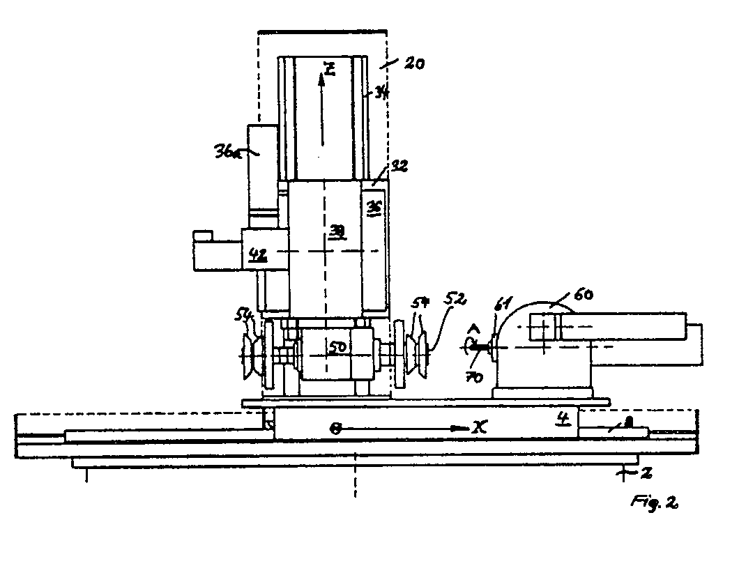
Description
Die Erfindung betrifft eine Werkzeug-Schleifmaschine mit einem Maschinen-Gestell, einem waagrecht längs der x-Achse verfahrbaren Tisch auf dem Gestell, einem ersten Teilapparat mit Spannfutter zum Einspannen eines Werkstücks, einem waagrecht längs der y-Achse und vertikal längs der z-Achse verfahrbaren Schleifkopf, und einer aus dem Schleifkopf herausragenden, antreibbaren Schleifspindel, an der zur Bearbeitung eines eingespannten Werkstücks eine Schleifscheibe befestigbar ist.The invention relates to a tool grinding machine with a machine frame, a table which can be moved horizontally along the x-axis on the frame, a first dividing device with a chuck for clamping a workpiece, a horizontally along the y-axis and vertically along the z-axis movable grinding head, and a grinding spindle which can be driven and protrudes from the grinding head and to which a grinding wheel can be attached for machining a clamped workpiece.
Bei derartigen bekannten Werkzeug-Schleifmaschinen sitzt der Schleifkopf an einer zylindrischen Höhensäule, die in einer entsprechenden zylindrischen Lagerbuchse gleitgelagert ist und vertikal längs der z-Achse verfahrbar ist. Um das Lagerspiel möglichst gering zu halten, muß der Durchmesser der Höhensäule und der entsprechenden Lagerbuchse möglichst groß sein. Außerdem darf bei dieser bekannten Werkzeugmaschine zur Erzielung einer starren Anordnung der Abstand zwischen Höhensäule und Arbeitstisch bzw. dem Werkstück nicht zu groß sein, um die Präzision der Werkzeugfertigung nicht zu beeinträchtigen. Großer Durchmesser der Höhensäule und geringer Abstand der Höhensäule vom Werkstück schränken jedoch den Freiraum am Werkstück beträchtlich ein, wodurch die Bewegungsmöglichkeiten des Schleifkopfes, und damit die Einsatzmöglichkeiten der Schleifmaschine beschränkt sind.In such known tool grinding machines, the grinding head is seated on a cylindrical column of height, which is slidably mounted in a corresponding cylindrical bearing bush and can be moved vertically along the z-axis. In order to keep the bearing clearance as small as possible, the diameter of the height column and the corresponding bearing bush must be as large as possible. In addition, in this known machine tool to achieve a rigid arrangement, the distance between the vertical column and the work table or the workpiece must not be too large in order not to impair the precision of the tool production. However, the large diameter of the height column and the small distance of the height column from the workpiece considerably restrict the free space on the workpiece, as a result of which the possibilities of movement of the grinding head and thus the possible uses of the grinding machine are limited.
Aufgabe der Erfindung ist es daher, eine Werkzeug-Schleifmaschine der eingangs genannten Art derart weiterzubilden, daß ein geringes Spiel der Höhenbewegung des Schleifkopfes, eine ausreichend starre Anbringung des Schleifkopfes und ausreichend großer Freiraum am Werkstück verwirklicht werden.The object of the invention is therefore to provide a tool grinding machine of the type mentioned in the introduction to further develop that a slight play in the vertical movement of the grinding head, a sufficiently rigid attachment of the grinding head and a sufficiently large free space on the workpiece are realized.
Diese Aufgabe wird bei der Werkzeug-Schleifmaschine der eingangs genannten Art erfindungsgemäß gekennzeichnet durch einen längs der y-Achse verfahrbaren vertikalen Maschinenständer, und einen an dem Maschinenständer vertikal verfahrbaren Support, an den der Schleifkopf um eine in einer vertikalen Ebene liegenden Achse (C-Achse) drehbar gelagert ist.This task is characterized according to the invention in the tool grinding machine of the type mentioned at the outset by a vertical machine stand which can be moved along the y axis, and a support which can be moved vertically on the machine stand and to which the grinding head is about an axis lying in a vertical plane (C axis ) is rotatably mounted.
Die Vorteile der Erfindung liegen insbesondere darin, daß statt der in einer zylindrischen Lagerbuchse gleitgelagerten, verfahrbaren Höhensäule ein vertikaler Maschinenständer vorgesehen wird, der vertikale Führungen trägt, in welchen ein den Schleifkopf tragender Support vertikal verfahrbar ist. Da der Maschinenständer - wie schon die bekannte Höhensäule - auch längs der y-Achse verfahren werden kann, und da der Schleifkopf am Support um eine in einer vertikalen Ebene liegenden Achse drehbar gelagert ist, wird mit der erfindungsgemäßen Schleifmaschine die bei bekannten Schleifmaschinen vorhandene 5-Achsenbahnsteuerung ebenfalls verwirklicht (x-Achse horizontal in Richtung des Tisches, y-Achse horizontal senkrecht zum Tisch, z-Achse Vertikalbewegung, A-Achse: Drehung des Werkstücks um die Achse des ersten Teilapparats, C-Achse: Rotation um eine vertikale Achse). Bei ausreichend starrem Aufbau des Maschinenständers, des Supports und der Halterung für den Schleifkopf und der Führung für die Vertikalbewegung des Supports läßt sich eine genaue, reprodu zierbare Positionssteuerung der Schleifscheibe verwirklichen. Damit einher geht eine beträchtliche Erhöhung des Freiraums am Werkstück, die bisher schwer oder nicht verwirklichbare Bewegungsabläufe des Schleifkopfes bzw. der Schleifscheibe zuläßt. Dieser Freiraum wird im wesentlichen dadurch gewonnen, daß zwischen dem Schleifkopf und dem Maschinenständer mittels des Supports ein ausreichender horizontaler Abstand verwirklicht wird, daß also die C-Achse einen vorgegebenen Abstand von der z-Achse aufweist, längs derer der Support vertikal geführt wird.The advantages of the invention are, in particular, that instead of the movable height column which is slidably mounted in a cylindrical bearing bush, a vertical machine stand is provided which carries vertical guides in which a support carrying the grinding head can be moved vertically. Since the machine stand - like the well-known height column - can also be moved along the y-axis, and since the grinding head on the support is rotatably supported about an axis lying in a vertical plane, the grinding machine according to the invention, which is available in known grinding machines, Axis path control also implemented (x-axis horizontally in the direction of the table, y-axis horizontally perpendicular to the table, z-axis vertical movement, A-axis: rotation of the workpiece around the axis of the first sub-apparatus, C-axis: rotation around a vertical axis) . With a sufficiently rigid structure of the machine stand, the support and the holder for the grinding head and the guide for the vertical movement of the support, an accurate, reproducible realizable position control of the grinding wheel. This is accompanied by a considerable increase in the free space on the workpiece, which allows movements of the grinding head or the grinding wheel that were previously difficult or impossible to achieve. This free space is essentially gained in that a sufficient horizontal distance is realized between the grinding head and the machine stand by means of the support, that is to say that the C axis has a predetermined distance from the z axis, along which the support is guided vertically.
Besonders bevorzugt ist die vertikale Führung für den Support an der dem Tisch zugewandten Außenfläche des Maschinenständers angeordnet. Der Support enthält bevorzugt ein in dieser Führung verfahrbares Basisteil und einen auf dem Basisteil um eine horizontale Achse (B-Achse) drehbar gelagerten Tisch, an dem der Schleifkopf - bevorzugt mittels eines an einer vertikalen Außenfläche des Drehtisches befestigten zweiten Teilapparats - angeordnet ist. Der Schleifkopf ist bei dieser Ausführungsform bevorzugt in dem Lager des zweiten Teilapparats drehbar gelagert, welches normalerweise das Spannfutter des Teilapparats aufnimmt. Diese Ausführungsform der Erfindung besitzt den wesentlichen Vorteil, daß zur Halterung des Schleifkopfes eine an sich bekannte Baueinheit, nämlich ein Teilapparat verwendet werden kann, und daß insbesondere durch die Aufspaltung des Supports in ein Basisteil und einen Drehtisch eine zusätzliche Drehbewegung um die B-Achse, mithin also eine 6-Achsenbahnsteuerung zuläßt. Es lassen sich daher mit der erfindungsgemäßen Schleifmaschine auch komplizierte Werkzeuge schleifen, die bisher mangels Freiraum und ins besondere mangels ausreichender Bewegbarkeit des Schleifkopfes nicht verwirklichbar waren.The vertical guide for the support is particularly preferably arranged on the outer surface of the machine stand facing the table. The support preferably contains a base part which can be moved in this guide and a table which is rotatably mounted on the base part about a horizontal axis (B axis) and on which the grinding head is arranged, preferably by means of a second part apparatus fastened to a vertical outer surface of the turntable. In this embodiment, the grinding head is preferably rotatably mounted in the bearing of the second sub-apparatus, which normally receives the chuck of the sub-apparatus. This embodiment of the invention has the essential advantage that a unit known per se, namely a dividing device, can be used to hold the grinding head, and that, in particular, by splitting the support into a base part and a rotary table, an additional rotary movement about the B axis, therefore allows a 6-axis path control. It is therefore also possible to grind complicated tools with the grinding machine according to the invention, which were previously lacking in clearance and ins particular were not feasible due to the lack of sufficient mobility of the grinding head.
Die erfindungsgemäße Schleifmaschine ist mit einem Hydrauliksystem versehen, welches so ausgebildet ist, daß der Drehtisch im Schleifbetrieb hydraulisch gegen das Basisteil des Supports angesaugt wird, also hydraulisch verklemmt wird. Außerdem läßt sich auch der Schleifkopf für den Schleifbetrieb gegen den zweiten Teilapparat hydraulisch verklemmen. Auf diese Weise wird eine besonders starre, nahezu spielfreie Verbindung zwischen dem Schleifkopf und dem Maschinenständer herbeigeführt, sobald der Schleifbetrieb einsetzt.The grinding machine according to the invention is provided with a hydraulic system which is designed such that the rotary table is sucked hydraulically against the base part of the support in the grinding operation, that is to say it is hydraulically clamped. In addition, the grinding head for the grinding operation can be clamped hydraulically against the second dividing head. In this way, a particularly rigid, almost backlash-free connection between the grinding head and the machine stand is established as soon as the grinding operation begins.
Es hat sich als vorteilhaft erwiesen, den Antriebsmotor für die Schleifspindel am zweiten Teilapparat mit einer zur Schleifspindel parallelen Welle anzubringen und dann die Schleifspindel über einen Transmissionsriemen anzutreiben. Dadurch wird der Freiraum um das Werkstück durch Antriebsaggregate nicht unnötig beschränkt.It has proven to be advantageous to mount the drive motor for the grinding spindle on the second sub-apparatus with a shaft parallel to the grinding spindle and then to drive the grinding spindle via a transmission belt. As a result, the free space around the workpiece is not unnecessarily restricted by drive units.
Der Maschinenständer ist bevorzugt in einer horizontalen Führung verfahrbar, die auf dem Maschinengestell befestigt ist. Als Führung für den Maschinenständer sowie als vertikale Führung für den Support werden bevorzugt entsprechend beabstandete Führungsschienen mit eingeschliffenen Kugelrillen verwendet, in denen die am Maschinenständer bzw. am Support befestigten entsprechenden Kugellager laufen.The machine stand can preferably be moved in a horizontal guide which is attached to the machine frame. Appropriately spaced guide rails with ground-in ball grooves, in which the corresponding ball bearings fastened to the machine stand or to the support run, are preferably used as a guide for the machine stand and as a vertical guide for the support.
Vorteilhafterweise wird der erste Teilapparat bei der erfindungsgemäßen Schleifmaschine vom Benutzer gesehen auf dem Tisch rechts vom Werkstück, und der zugehörige Reitstock links vom Werkstück bzw. dem Schleifkopf angeordnet. Da die herzustellenden Werkzeuge üblicherweise alle einen Spanraum mit Rechtsdrall besitzen, liegen die Schneidkanten dieser Werkzeuge dann - vom Benutzer der Maschine her gesehen - vor der Schleifscheibe der Schleifmaschine, d.h. sie sind für den Benutzer sichtbar, so daß der Benutzer die Steuerung der Schleifscheibe und die Ölabgabe etc. optisch ständig unter Kontrolle halten kann.The first sub-apparatus in the grinding machine according to the invention is advantageously seen by the user on the table to the right of the workpiece, and the associated tailstock to the left of the workpiece or grinding head. Since the tools to be produced usually all have a chip space with a right-hand twist, the cutting edges of these tools are then - seen from the user of the machine - in front of the grinding wheel of the grinding machine, ie they are visible to the user, so that the user can control the grinding wheel and the Can keep oil release etc. visually under control.
Vorteilhafte Weiterbildungen der Erfindung sind durch die Merkmale der Unteransprüche gekennzeichnet.Advantageous developments of the invention are characterized by the features of the subclaims.
Im folgenden wird ein Ausführungsbeispiel der Erfindung anhand der Zeichnung näher erläutert. Es zeigen:
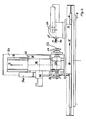
- Fig. 1 eine Seitenansicht einer Werkzeug-Schleifmaschine ohne ersten Teilapparat;
- Fig. 2 eine Frontansicht der Schleifmaschine gemäß Fig. 1 mit dem ersten Teilapparat; und
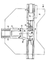
- Fig. 3 eine Aufsicht auf die Schleifmaschine gemäß Fig. 2.
- Figure 1 is a side view of a tool grinding machine without a first sub-apparatus.
- FIG. 2 shows a front view of the grinding machine according to FIG. 1 with the first sub-apparatus; and
- 3 is a plan view of the grinding machine according to FIG. 2.
Die in den Fig. 1 bis 3 dargestellte Werkzeug-Schleifmaschine besitzt ein Maschinengestell 2, auf dem zwei parallele Führungsschienen 8 mit eingeschliffenen Kugelrillen längs einer x-Achse befestigt sind. Ein Tisch 4 besitzt auf seiner Unterseite in entsprechendem Abstand voneinander angeordnete Kugellager 6, die in den Laufrillen der Führungsschienen 8 laufen, so daß der Tisch 4 auf der waagerechten Arbeitsfläche des Maschinengestells 2 längs der x-Achse verfahrbar ist. Wie insbesondere in Fig. 2 darge stellt, ist auf dem Tisch 4 ein erster Teilapparat 60 befestigt, der ein Spannfutter 61 zur Aufnahme eines zu bearbeitenden Werkstücks 70 trägt. In vorgegebenem Abstand von dem ersten Teilapparat 60 ist erforderlichenfalls ein Reitstock auf den Tisch 4 aufspannbar, um das freie Ende des Werkstücks 70 abzustützen.The tool grinding machine shown in FIGS. 1 to 3 has a
Auf dem Maschinengestell 2 sind - senkrecht zu dem Tisch 4 -, also in y-Richtung zwei Führungsschinen 24 befestigt, die ebenfalls eingeschliffene Kugelrillen aufweisen. Auf einer Grundplatte 22 ist ein vertikaler Maschinenständer 20 befestigt. Unterhalb der Grundplatte 22 sind Kugellager 23 in vorgegebenem Abstand voneinander angeordnet, die in den Kugelrillen der Führungsschienen 24 laufen. Mittels der aus Kugellagern 23 und Führungsschienen 24 gebildeten Führung ist der Maschinenständer 20 längs einer y-Achse waagrecht verfahrbar.On the machine frame 2 - perpendicular to the table 4 -, ie in the y-direction, two
Am Maschinenständer 20 sind - auf der dem Tisch 4 zugewandten Seite - zwei weitere Führungsschienen 34 in vertikaler Richtung befestigt, die ebenfalls eingeschliffene Kugelrillen aufweisen und als vertikale Führung für einen Support 30 dienen. Der Support 30 besteht aus einem Basisteil 32, an dem in vorgegebenem Abstand voneinander mehrere Kugellager 33 befestigt sind, die in den Kugelrillen der Führungsschienen 34 laufen. Auf dem Basisteil 32 ist ein Drehtisch 36 angeordnet, der um eine horizontale Achse, die sogenannte B-Achse drehbar auf dem Basisteil 32 gelagert ist und mittels eines Antriebsmotors 36a gedreht werden kann. Der Support enthält ferner einen zweiten Teilapparat 38, der an einer vertikalen Außenfläche 37 des Drehtisches 36 befe stigt ist. In dem zylindrischen Lager 40 des zweiten Teilapparats 38, welches ansonsten zur Aufnahme eines Spannfutters dient, ist ein Schleifkopf 50 um eine in einer vertikalen Ebene liegenden Achse, die sogenannte C-Achse drehbar gelagert. Im Schleifkopf ist - quer zur C-Achse - eine antreibbare Schleifspindel 52 gelagert, die an einem aus dem Schleifkopf herausragenden freien Ende eine oder mehrere Schleifscheiben 54 aufnimmt, mittels der das Werkstück 70 bearbeitet wird. Über dem Schleifkopf 50 ist in vorgegebenem Abstand und mit parallel zum Schleifkopf 50 verlaufender Welle am zweiten Teilapparat 38 ein Antriebsmotor 42 angebracht, der die Schleifspindel 52 über geeignete Transmissionselemente, z.B. einen Riemenantrieb antreibt.On the machine stand 20 - on the side facing the table 4 - two
Die Schleifmaschine enthält ein Hydrauliksystem (nicht dargestellt), welches zum Bewegen der verschiedenen Baueinheiten, wie Maschinenständer, Support, Tisch und/oder Drehtisch sowie Schleifkopf dient. Alternativ sind elektrische Antriebsmotoren zum Antreiben dieser Maschineneinheiten mög- lich, wobei dann die Drehbewegung der Antriebsmotoren mittels Spindelantriebe in die erforderlichen Transalationsbewegungen umsetzbar sind.The grinding machine contains a hydraulic system (not shown), which serves to move the various structural units, such as the machine stand, support, table and / or rotary table and grinding head. Alternatively, electric drive motors for driving these machine units are possible, in which case the rotary movement of the drive motors can then be converted into the required translational movements by means of spindle drives.
Mittels des Hydrauliksystems ist es erfindungsgemäß möglich, den Schleifkopf 50 - im Schleifbetrieb - zur Erzielung einer möglichst starren Verbindung gegen den zweiten Teilapparat 38 hydraulisch anzusaugen, also hydraulisch zu "verkelmmen". In gleicher Weise läßt sich - im Schleifbetrieb - der Drehtisch 36 zur Erzielung einer möglichst starren Verbindung hydraulisch gegen das Basisteil 32 des Supports 30 verklemmen.By means of the hydraulic system, it is possible according to the invention to hydraulically suck in the grinding head 50 - in the grinding operation - in order to achieve a connection which is as rigid as possible against the
Claims (11)
einem waagrecht längs der x-Achse verfahrbaren Tisch auf dem Gestell,
einem ersten Teilapparat mit Spannfutter zum Einspannen eines Werkstückes,
einem waagrecht längs der y-Achse und vertikal längs der z-Achse verfahrbaren Schleifkopf, und
einer aus dem Schleifkopf herausragenden, antreibbaren Schleifspindel, an der zur Bearbeitung eines eingespannten Werkstücks eine Schleifscheibe befestigbar ist,
gekennzeichnet durch einen längs der y-Achse verfahrbaren vertikalen Maschinenständer (20), und
einen an dem Maschinenständer (20) vertikal verfahr baren Support (30), an den der Schleifkopf (50) um eine in einer vertikalen Ebene liegenden Achse (C-Achse) drehbar gelagert ist.1. Tool grinding machine with a machine frame,
a table on the frame that can be moved horizontally along the x-axis,
a first sub-apparatus with a chuck for clamping a workpiece,
a grinding head which can be moved horizontally along the y axis and vertically along the z axis, and
a drivable grinding spindle protruding from the grinding head, to which a grinding wheel can be attached for machining a clamped workpiece,
characterized by a vertical machine stand (20) movable along the y-axis, and
one vertically on the machine stand (20) baren support (30), on which the grinding head (50) is rotatably mounted about an axis lying in a vertical plane (C axis).
dadurch gekennzeichnet, daß der Drehtisch (36) im Schleifbetrieb zur Erzielung einer starren Verbindung hydraulisch gegen das Basisteil (32) des Supports (30) verklemmbar ist.4. Tool grinding machine according to one of the preceding claims,
characterized in that the rotary table (36) can be clamped hydraulically against the base part (32) of the support (30) in order to achieve a rigid connection.
dadurch gekennzeichnet, daß der Schleifkopf (50) im Schleifbetrieb zur Erzielung einer starren Verbindung gegen den zweiten Teilapparat (38) hydraulisch verklemmbar ist.5. Tool grinding machine according to one of the preceding claims,
characterized in that the grinding head (50) can be hydraulically clamped against the second sub-apparatus (38) in order to achieve a rigid connection.
dadurch gekennzeichnet, daß der Antriebsmotor (42) der mit einer zur Schleifspindel (52) parallelen Welle an dem zweiten Teilapparat (38) angeordnet ist und die Schleifspindel (52) mittels eines Treibriemens antreibt.6. Tool grinding machine according to one of the preceding claims,
characterized in that the drive motor (42) which is arranged on the second sub-assembly (38) with a shaft parallel to the grinding spindle (52) and drives the grinding spindle (52) by means of a drive belt.
dadurch gekennzeichnet, daß der Maschinenständer (20) in einer auf dem Maschinengestell (2) befestigten Führung (22, 24) horizontal verfahrbar ist.7. Tool grinding machine according to one of the preceding claims,
characterized in that the machine stand (20) can be moved horizontally in a guide (22, 24) attached to the machine frame (2).
dadurch gekennzeichnet, daß an der Schleifspindel (52) mehrere Schleifscheiben (54) befestigbar sind.8. Tool grinding machine according to one of the preceding claims,
characterized in that a plurality of grinding wheels (54) can be attached to the grinding spindle (52).
dadurch gekennzeichnet, daß der erste Teilapparat (60), vom Benutzer gesehen, auf dem Tisch (4) rechts, und der zugehörige Reitstock (62) links von dem Schleifkopf (50) befestigbar sind.9. Tool grinding machine according to one of the preceding claims,
characterized in that the first sub-apparatus (60), seen by the user, can be fastened on the table (4) on the right, and the associated tailstock (62) on the left of the grinding head (50).
dadurch gekennzeichnet, daß die horizontale Führung (23, 24) für den Maschinenständer (20) zwei parallele, am Maschinengestell (2) befestigte Führungsschienen (24) mit eingeschliffenen Kugelrillen und am Maschinenständer (20) entsprechende Kugellager (23) enthält.10. Tool grinding machine according to one of the preceding claims,
characterized in that the horizontal guide (23, 24) for the machine stand (20) contains two parallel guide rails (24) fastened to the machine frame (2) with ground-in ball grooves and corresponding ball bearings (23) on the machine stand (20).
dadurch gekennzeichnet, daß die vertikale Führung (33, 34) zwei parallele, an der dem Tisch (4) zugewandten Seite des Maschinenständers (20) befestigte Führungsschienen (34) mit eingeschliffenen Kugelrillen, und an dem Basisteil (32) entsprechende Kugellager (33) enthält.11. Tool grinding machine according to one of the preceding claims,
characterized in that the vertical guide (33, 34) has two parallel guide rails (34) fastened to the side of the machine stand (20) facing the table (4) with ground-in ball grooves, and corresponding ball bearings (33) to the base part (32) contains.
Applications Claiming Priority (2)
| Application Number | Priority Date | Filing Date | Title |
|---|---|---|---|
| DE19883804010 DE3804010A1 (en) | 1988-02-10 | 1988-02-10 | TOOL GRINDING MACHINE |
| DE3804010 | 1988-02-10 |
Publications (2)
| Publication Number | Publication Date |
|---|---|
| EP0328034A2 true EP0328034A2 (en) | 1989-08-16 |
| EP0328034A3 EP0328034A3 (en) | 1991-05-02 |
Family
ID=6347045
Family Applications (1)
| Application Number | Title | Priority Date | Filing Date |
|---|---|---|---|
| EP19890102053 Withdrawn EP0328034A3 (en) | 1988-02-10 | 1989-02-07 | Tool-grinding machine |
Country Status (3)
| Country | Link |
|---|---|
| EP (1) | EP0328034A3 (en) |
| JP (1) | JPH01316157A (en) |
| DE (1) | DE3804010A1 (en) |
Cited By (7)
| Publication number | Priority date | Publication date | Assignee | Title |
|---|---|---|---|---|
| EP0424815A1 (en) * | 1989-10-23 | 1991-05-02 | Z. BAVELLONI S.p.A. | Automatic engraving machine, particularly for engraving the faces of plate-like elements in general and of glass plates in particular |
| WO1995004629A1 (en) * | 1993-08-07 | 1995-02-16 | Strausak Ag Maschinenfabrik | Universal grinding station |
| CN104044077A (en) * | 2013-03-15 | 2014-09-17 | 昆山齐升磨料磨具有限公司 | Novel surface grinder |
| CN105479287A (en) * | 2016-01-15 | 2016-04-13 | 商丘金振源电子科技有限公司 | Three-shaft deburring system |
| CN107414188A (en) * | 2017-09-22 | 2017-12-01 | 苏州欣航微电子有限公司 | A machine reamer rotating device for machining |
| CN108705415A (en) * | 2018-07-03 | 2018-10-26 | 杨真 | A kind of horizontal auto parts machinery processing grinding device |
| US10421172B2 (en) * | 2015-12-01 | 2019-09-24 | Tokyo Seimitsu Co. Ltd. | Processing device |
Families Citing this family (4)
| Publication number | Priority date | Publication date | Assignee | Title |
|---|---|---|---|---|
| CN100537140C (en) * | 2008-03-28 | 2009-09-09 | 重庆三磨海达磨床有限公司 | Grinding attachment suitable for freely curved face |
| CN103753364A (en) * | 2014-01-14 | 2014-04-30 | 苏州苏铸重工有限公司 | Numerical control grinding machine tool |
| CN105458862A (en) * | 2015-12-16 | 2016-04-06 | 江苏森莱浦光电科技有限公司 | UHP bulb grinding machine |
| CN106141822A (en) * | 2016-08-26 | 2016-11-23 | 马鞍山俊强精密机械设备有限公司 | A kind of cutting disc computer controlled grinding machine and method for grinding thereof |
Family Cites Families (5)
| Publication number | Priority date | Publication date | Assignee | Title |
|---|---|---|---|---|
| FR1355181A (en) * | 1962-04-16 | 1964-03-13 | Hammond Machinery Builders Inc | Polishing process and polishing machine for its implementation |
| SE316706B (en) * | 1964-04-06 | 1969-10-27 | Ulvsunda Verkstaeder Ab | |
| US4186529A (en) * | 1977-06-28 | 1980-02-05 | S. E. Huffman Corporation | Programmably controlled method for grinding end cutting tools and the like |
| FR2462232A1 (en) * | 1979-08-02 | 1981-02-13 | Treuillet Bernard | IMPROVEMENTS TO MACHINES FOR SHARPENING MACHINING TOOLS |
| DE3538795A1 (en) * | 1985-10-31 | 1987-05-07 | Volker Zang | GRINDING HEAD FOR A TOOL GRINDING MACHINE FOR SPIRAL SLOTED CUTTING TOOLS |
-
1988
- 1988-02-10 DE DE19883804010 patent/DE3804010A1/en not_active Withdrawn
-
1989
- 1989-02-07 EP EP19890102053 patent/EP0328034A3/en not_active Withdrawn
- 1989-02-10 JP JP3253989A patent/JPH01316157A/en active Pending
Cited By (8)
| Publication number | Priority date | Publication date | Assignee | Title |
|---|---|---|---|---|
| EP0424815A1 (en) * | 1989-10-23 | 1991-05-02 | Z. BAVELLONI S.p.A. | Automatic engraving machine, particularly for engraving the faces of plate-like elements in general and of glass plates in particular |
| WO1995004629A1 (en) * | 1993-08-07 | 1995-02-16 | Strausak Ag Maschinenfabrik | Universal grinding station |
| CN104044077A (en) * | 2013-03-15 | 2014-09-17 | 昆山齐升磨料磨具有限公司 | Novel surface grinder |
| US10421172B2 (en) * | 2015-12-01 | 2019-09-24 | Tokyo Seimitsu Co. Ltd. | Processing device |
| CN105479287A (en) * | 2016-01-15 | 2016-04-13 | 商丘金振源电子科技有限公司 | Three-shaft deburring system |
| CN107414188A (en) * | 2017-09-22 | 2017-12-01 | 苏州欣航微电子有限公司 | A machine reamer rotating device for machining |
| CN107414188B (en) * | 2017-09-22 | 2019-02-22 | 广东泓睿科技有限公司 | A machine reamer rotating device for machining |
| CN108705415A (en) * | 2018-07-03 | 2018-10-26 | 杨真 | A kind of horizontal auto parts machinery processing grinding device |
Also Published As
| Publication number | Publication date |
|---|---|
| JPH01316157A (en) | 1989-12-21 |
| EP0328034A3 (en) | 1991-05-02 |
| DE3804010A1 (en) | 1989-08-24 |
Similar Documents
| Publication | Publication Date | Title |
|---|---|---|
| EP1338376B1 (en) | Milling machine for milling and turning rod shaped material | |
| DE3005606C2 (en) | Numerically controlled machine for grinding several different surfaces on one and the same workpiece | |
| DE3502328C2 (en) | ||
| DE3511614A1 (en) | MACHINE TOOL FOR MULTIPLE SURFACE MACHINING | |
| WO2001083159A1 (en) | Device for mechanically rough machining and/or finish machining cast parts | |
| DE4444614A1 (en) | Machine tool | |
| DE3917913A1 (en) | Electrodischarge wire cutting apparatus | |
| DE3315948C2 (en) | ||
| EP1525065B1 (en) | Machine tool with two workpiece spindles | |
| DE69114514T2 (en) | CUTTING AND GRINDING DEVICE FOR A GLASS DISC EDGE. | |
| DE3804010A1 (en) | TOOL GRINDING MACHINE | |
| DE3904686C1 (en) | CNC-machine for grinding workpieces with curved surfaces, in particular turbine blades, and also for grinding and polishing decorative grooves on hollow glassware or similar workpieces | |
| DE69126135T2 (en) | Portal machine tool | |
| DE880836C (en) | Device for processing elongated, flat or slightly convex, any inclined surfaces | |
| EP4058237A1 (en) | Circular grinding machine with dressing unit | |
| DE202004016057U1 (en) | Miniature machining center with multi-axis drilling and milling tool | |
| AT398051B (en) | ROTARY WIRE CUTTING MACHINE | |
| DE3707230C2 (en) | ||
| EP0307830A2 (en) | Driving device for a machine tool slide | |
| DE2620477C2 (en) | Vibratory grinding or polishing machine | |
| DE2217352A1 (en) | WORKPIECE CLAMPING TABLE | |
| DE3401086C2 (en) | ||
| DE4211738C2 (en) | Device for the stationary operation of motor-driven cutting hand tools | |
| DE8801687U1 (en) | Tool grinding machine | |
| DE3414886C1 (en) | Machine tool |
Legal Events
| Date | Code | Title | Description |
|---|---|---|---|
| PUAI | Public reference made under article 153(3) epc to a published international application that has entered the european phase |
Free format text: ORIGINAL CODE: 0009012 |
|
| AK | Designated contracting states |
Kind code of ref document: A2 Designated state(s): AT BE CH DE ES FR GB GR IT LI LU NL SE |
|
| RAP1 | Party data changed (applicant data changed or rights of an application transferred) |
Owner name: BREMER VULKAN AG SCHIFFBAU UND MASCHINENFABRIK |
|
| RIN1 | Information on inventor provided before grant (corrected) |
Inventor name: BUESSENSCHUETT, HEINZ |
|
| PUAL | Search report despatched |
Free format text: ORIGINAL CODE: 0009013 |
|
| AK | Designated contracting states |
Kind code of ref document: A3 Designated state(s): AT BE CH DE ES FR GB GR IT LI LU NL SE |
|
| RAP1 | Party data changed (applicant data changed or rights of an application transferred) |
Owner name: H. WOHLENBERG KG GMBH & CO. |
|
| 17P | Request for examination filed |
Effective date: 19911031 |
|
| RAP1 | Party data changed (applicant data changed or rights of an application transferred) |
Owner name: GUEHRING AUTOMATION GMBH |
|
| 17Q | First examination report despatched |
Effective date: 19920916 |
|
| STAA | Information on the status of an ep patent application or granted ep patent |
Free format text: STATUS: THE APPLICATION HAS BEEN WITHDRAWN |
|
| 18W | Application withdrawn |
Withdrawal date: 19930123 |