EP0328093A2 - Convertisseur de code de gray avec signal de défaut - Google Patents
Convertisseur de code de gray avec signal de défaut Download PDFInfo
- Publication number
- EP0328093A2 EP0328093A2 EP89102218A EP89102218A EP0328093A2 EP 0328093 A2 EP0328093 A2 EP 0328093A2 EP 89102218 A EP89102218 A EP 89102218A EP 89102218 A EP89102218 A EP 89102218A EP 0328093 A2 EP0328093 A2 EP 0328093A2
- Authority
- EP
- European Patent Office
- Prior art keywords
- signals
- signal
- gray code
- switching mechanism
- register
- Prior art date
- Legal status (The legal status is an assumption and is not a legal conclusion. Google has not performed a legal analysis and makes no representation as to the accuracy of the status listed.)
- Withdrawn
Links
Images

Classifications
-
- G—PHYSICS
- G01—MEASURING; TESTING
- G01D—MEASURING NOT SPECIALLY ADAPTED FOR A SPECIFIC VARIABLE; ARRANGEMENTS FOR MEASURING TWO OR MORE VARIABLES NOT COVERED IN A SINGLE OTHER SUBCLASS; TARIFF METERING APPARATUS; MEASURING OR TESTING NOT OTHERWISE PROVIDED FOR
- G01D5/00—Mechanical means for transferring the output of a sensing member; Means for converting the output of a sensing member to another variable where the form or nature of the sensing member does not constrain the means for converting; Transducers not specially adapted for a specific variable
- G01D5/12—Mechanical means for transferring the output of a sensing member; Means for converting the output of a sensing member to another variable where the form or nature of the sensing member does not constrain the means for converting; Transducers not specially adapted for a specific variable using electric or magnetic means
- G01D5/244—Mechanical means for transferring the output of a sensing member; Means for converting the output of a sensing member to another variable where the form or nature of the sensing member does not constrain the means for converting; Transducers not specially adapted for a specific variable using electric or magnetic means influencing characteristics of pulses or pulse trains; generating pulses or pulse trains
- G01D5/249—Mechanical means for transferring the output of a sensing member; Means for converting the output of a sensing member to another variable where the form or nature of the sensing member does not constrain the means for converting; Transducers not specially adapted for a specific variable using electric or magnetic means influencing characteristics of pulses or pulse trains; generating pulses or pulse trains using pulse code
- G01D5/2492—Pulse stream
-
- H—ELECTRICITY
- H03—ELECTRONIC CIRCUITRY
- H03M—CODING; DECODING; CODE CONVERSION IN GENERAL
- H03M1/00—Analogue/digital conversion; Digital/analogue conversion
- H03M1/12—Analogue/digital converters
- H03M1/22—Analogue/digital converters pattern-reading type
- H03M1/24—Analogue/digital converters pattern-reading type using relatively movable reader and disc or strip
- H03M1/28—Analogue/digital converters pattern-reading type using relatively movable reader and disc or strip with non-weighted coding
- H03M1/285—Analogue/digital converters pattern-reading type using relatively movable reader and disc or strip with non-weighted coding of the unit Hamming distance type, e.g. Gray code
-
- H—ELECTRICITY
- H03—ELECTRONIC CIRCUITRY
- H03M—CODING; DECODING; CODE CONVERSION IN GENERAL
- H03M13/00—Coding, decoding or code conversion, for error detection or error correction; Coding theory basic assumptions; Coding bounds; Error probability evaluation methods; Channel models; Simulation or testing of codes
Definitions
- the invention relates to a method and a circuit arrangement for converting Gray code signals into counting pulses and for forming a counter reading, for detecting interference signals violating Gray code and for forming an error signal.
- Gray code signals are often obtained from precision scans in precision dimension measuring machines via the intermediate stage of sine and cosine signals, transmitted to an evaluation device and processed there as a measurement result via a counter to give a coordinate.
- interference signals for example electromagnetically coupled from the environment.
- Interference signals that deviate significantly from the measurement signals with their time profile, in particular form shorter pulses, can be filtered out. This is carried out with the HCTL 2000 quadrature decoder from Hewlett Packard (Technical Data April 1986).
- Interference signals with a time behavior similar to the measurement signals on only one input line are generally not a problem if they simulate an up and a down counting event with their switch-on and switch-off edges, which results in zero in total and therefore remains ineffective.
- Signals that are only impressed on one input line can also lead to a Gray code violation if they coincide with one of their signal edges with an edge of a measurement signal on another line.
- the up and down counting pulses are also not reliably separated in time, which can result in malfunctions of the counter.
- Gray code violations are also possible due to interference signals on only one signal line if an edge of an interference signal coincides with the edge of a measurement signal on another line.
- the invention has for its object to limit the number of error messages to the necessary extent.
- Known generic circuit arrangements are simply to be substituted.
- the advantages achieved by the invention are, in particular, that the interruptions in measurement sequences are reduced to a minimum by error messages.
- the invention can take the place of previously known generic circuit arrangements without requiring changes to the upstream or downstream functional elements.
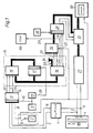
- 1 shows a known, for example optoelectronic, scale scanning device 1, which outputs a sinX-proportional output signal 2 and a cosX-proportional output signal 3 depending on the X position of an object.
- two square-wave logic signals 5,6 are generated from the two sinX and cosX proportional signals 2, 3, which are phase-shifted by 90 ° relative to one another, and which occur at each zero crossing of the sinX or cosX signal 2 , 3 have a signal edge or level change.
- the pair of square-wave logic signals 5, 6 represent gray code signals, since at most one signal 5 or 6 has a signal edge.
- a reset signal 8 can be triggered by a switching device 7.
- a clock generator 9 generates a clock signal 10 with a specific clock frequency.
- the two square-wave logic signals 5, 6 and the reset signal 8 are applied to the inputs of a register 11, which is controlled by the clock signal 10.
- the pending at a time determined by the clock signal 10 t0 at the inputs of the register 11 level of the signals 5,6 and 8 are switched through to the outputs of the register and held during the time interval until the next clock signal 10 at a time t 1, at which time the levels pending at time t 1 are switched through.
- the register 11 thus forms the gray code output signals 12 and 13 from the two input signals 5 and 6 and the reset output signal 14 from the reset input signal 8.
- the output signals 12, 13 and 14 are synchronized with the clock signal 10 and are always fixed for a fixed time interval.
- the synchronized output signals 12, 13 and 14 are connected to the inputs of a clocked switching mechanism 15, which in this example is based on the model of a Moore machine and consists of a transfer switching network 16, a register 17 and out an output switching network 18.
- the Moore automaton is determined by this (Steinbuch, Rupprecht, ed .: sympathetic activator, ed .: sympathetic activator, a rotary switch, or the like.
- the outputs of the transfer switching network 16 are not only fed to the output switching network 18 via the register 17, but are also fed back to inputs of the transfer switching network 16.
- the register 17 is controlled by the clock generator 9 via a delay element 19 with a clock signal 20 which has the same frequency as the clock signal 10 but is delayed taking into account the signal propagation times in the elements 11, 16 and 17. It is possible and implemented in the example that the output switching network 18 as a trivial unit switching network, i. H. to be implemented as a direct through connection from input to output.
- the output switching network 18 therefore contains no components and can therefore not cause any faults. All links must therefore be combined in the transfer switching network 16.
- switchgears and automats are known from communications technology (Steinbach, Rupprecht, d. 0.) And are explained in more detail below for the application in this example with reference to FIG. 2.
- the clocked switching mechanism 15 delivers two counting pulses 21 and 22 and an error signal 23 as the output signal.
- the counting pulses 21, 22 are implemented as down (21) and up (22) counting signals.
- the error signal 23 is fed to an error reporting device 28.
- this error reporting device 28 can also take over automatic functions such as the abort of a measurement process, a new start from a defined initial position, and the reset signal 8 being triggered.
- the outputs of the counter 26 and the counter status signals 24 and 25 are fed to a register 29 which is controlled by a further clock generator 30.
- the output signals of the register 29 and the fine interpolator 27 are fed to a synchronization device 31, which forms the final measured value from the input signals and feeds them to an output unit 32 via their output signals.
- the output unit 32 can be a display for the operator in the simplest case, but usually also includes the transfer to automatic storage and computing systems.
- the switching mechanism 15, the counter 26 and the output 32 can be brought into a basic position by the reset signal 8.
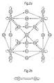
- FIG. 2 shows the state transition graph of a Moore automaton as a model for the clocked switching mechanism 15 in FIG. 1, the automaton generating the error signal 23 under the conditions according to the invention and acting as a quadruple interpolator, ie for every level change of the input signals 12 and 13 and thus generates a counting pulse 21 (down) or 22 (up) four times per period of the sinX signal 2.
- the machine has 20 states S1 to S20, which are characterized by the combination of the logical values of signals 21 to 25 and other internal signals (e.g. 33.34). All input (12 to 14) and status signals (21 to 25, 33, 34) are square-wave signals, one level of which is assigned the logical "1" and the other level of which is the logical "0".
- the state transition graph is divided into two parts (FIGS. 2a and 2b).
- 2a shows the partial state transition graph for the 18 states S3 to S20.
- the states of the machine are represented by circles.
- the state S3 is shown six times. This allows a clear two-dimensional representation. Arrows indicate transitions between the states.
- the transition from the Si state takes place along one of these through the transition into the time interval N + 1 Combination of 12, 13 and 14 specific arrow to a state Sj.
- State S3 is the basic state. It is reached from states S5 to S8 and S17 to S20 when the input signal 14, the reset signal, is activated.
- State S4 controls the transitions between states S1 and S2 in FIG. 2b and thus the error message at error output 23.
- S4 can be reached from states S17 to S20 and always changes to the basic state S3.
- S5 to S8 are idle states. They are distinguished from one another by signals 24 and 25.
- the states S9 to S16 lie in the state transition graph between idle states S5 to S8; they are always reached from an idle state S5 to S8 and change again to an idle state S5 to S8 in the next time interval of the clock cycle 20.
- a count pulse 21, 22 is generated by this sequence.
- Four of the states S9 to S16 are up and down count pulse generators.
- the states S17 to S20 are reached from the idle states S5 to S8 when the input signals 12 and 13 have a Gray code error. If only one of the input signals 12 or 13 changes in a subsequent time interval of the clock cycle 20, the states S17 to S20 change to the state S4. This causes an error message below. Without changing the input signals 12 and 13, the state S17 to S20 remains. When both input signals 12 and 13 change, the automaton falls back into the previous idle state S5 to S8, thereby avoiding unnecessary error messages.
- 2b shows the partial state transition graph for the states S1 and S2 "error status set" in the same representation.
- the states are identified by signal 23.
- state S2 signal 23 is activated and the error message is thus output.
- the transition from state S1 to state S2 takes place when state S4 is reached in the partial state transition graph FIG. 2a.
- the state S1 is reached from the state S2 when the reset signal 14 is activated.
- the two signals 5 and 6 together show four signal edges. This is also the case after the synchronization in register 11 for signals 12 and 13.
- the signal edge repetition frequency at the inputs of the clocked switching mechanism 15 is therefore four times the signal frequency of 5 or 6.
- a counting event (for example S8-S12-S7) requires two transitions, that is to say two time intervals of the clock pulse 20. Therefore the clock frequency of the clock pulse 20 and thus also the time cycle 10 - be at least eight times the largest signal frequency.
- the shortest pulse duration of an interference signal on the signal inputs 12 or 13 of the switching mechanism 15 is just equal to a time interval of the timing clock 10 or 20 through the register 11.
- the clock frequency of the clock 10 or 20 is selected at least 20 times as large as the signal frequency, so that there are at least five time intervals of the clock 10 and 20 between every two edges of the measurement signals on the signal lines 12 and 13.
- a single interference pulse on a line 12 or 13 can lead to an up and down counting pulse pair 22 and 21 with the sum zero and a double gray code violation can also be detected. Most of the malfunctions can thus be processed harmlessly.
- the maximum permissible clock frequency of the clock cycle 10 or 20 is determined by the maximum signal propagation times in the switching elements 11, 16 to 18 or 47 to 50 and 26.
- the design of the state transition graph (FIG. 2) which requires at least two transitions and thus time intervals of the clock cycle 20 per count pulse 21 or 22, also has the advantage that the count pulses 21 or 22 with their duration of one time interval of the clock cycle 20 never can follow one another without a pause, so that malfunctions of the counter 26 are avoided.
- FIG. 3 shows a signal state diagram which shows, by way of example, the chronological sequence of the input signals 12 and 13 and the states S4 to S20 controlled thereby for the Moore automaton according to the state transition graph in FIG. 2.
- the states S1 and S2 (FIG. 2b) are not directly influenced by the input signals 12 and 13, as is the basic state S3, which is reached from S4 or by the reset signal 14.
- 3a shows an example of an undisturbed signal sequence.
- the clock frequency is twenty times the maximum signal frequency and this is fully utilized, i. H.
- An input signal 12 or 13 changes after every five time intervals of the time cycle.
- the clock cycle 10 the input signals 12 and 13, the states Si from S4 to S20, their meaning and the counter reading of the counter 26 are shown one above the other.
- the states Si are assumed in the real switching mechanism 15 in the rhythm of the timing clock 20, which is phase-shifted against the timing clock 10 of the register 11 and the input signals 12 and 13.
- the meaning of the states Si is indicated by arrows for the generation of the up (22) and down (21) counting pulses.
- An exclamation mark identifies the states S17 to S20 that are reached when the input signals 12 and 13 have a Gray code error.
- 3b shows examples of interference pulses which occur simultaneously on both input signals 12 and 13. Regardless of the polarity of the interference pulses, the counting is not impaired in Examples 35 and 36, the first Gray code violation leads to states S17 and S20 and the following second Gray code violation leads back to an idle state S5 and S7 .
- Example 37 This is different in Example 37, where the interference pulse in the input signal 12 "swallows" a measurement signal change. As a result, the leading edge of the interference pulse on the input signal 12 is also not recognizable. The leading edge of the glitch on the input signal 13 therefore causes an incorrect down count. Only the trailing edge of the interference pulse occurs on both input signals 12 and 13, this gray code violation causes the transition to state S17. The next change in the measurement signal does not result in a gray code violation, and so the transition takes place to state S4 "report gray code error” and subsequently to S2 "error status set", where error signal 23 is activated, and to basic state S3.
- Fig. 3c shows an example of the fact that interference pulses on only one input signal 12 or 13 can lead to Gray code violations.
- leading and trailing edges of the interference pulse on the input signal 13 coincide with two measuring signal edges on the input signal 12.
- Even without an interference pulse the two edges of the measurement signal on the input signal 12 would not have resulted in a total count, since an up and a down counter event cancel each other out.
- an interference pulse has its leading edge at the same time as the edge of a measurement signal on the other input signal 13. This gray code error causes the transition to state S17. With the trailing edge of the interference pulse, only one input signal 12 changes and therefore the transition from state S17 to state S4 "report gray code error" takes place.
- the states of the machine are u. a. determined by signals 24 and 25. It has already been shown above that these signals 24 and 25 can also be routed as an option to the output of the clocked switching mechanism 15 in order to synchronize a fine interpolator 27 with the quadruple interpolator.
- a counting process of the clocked switching mechanism 15, which is designed as a quadruple interpolator always goes from a subsequent state (for example S7) to a counting pulse generator state (for example S13) and further to a next subsequent state (for example S5). leads, the changed up or down count signal 21 or 22 is reset. Synchronously with this, one of the signals 24 or 25 changes its level.
- Signals 24 and 25 thus form a 2-bit Gray code counter, which is used internally to distinguish between the subsequent states S5 to S8. Their logical value indicates the quadrant of the sinX and cosX input functions 2 and 3 of the quadruple interpolator. Their use for the synchronization of a fine interpolation device is described below.
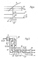
- FIG. 4 shows how, for example, in the case of a sampling 42 (clock signal 10) which occurs immediately after a zero crossing 41 of the sinX (t) signal 2 because of the necessary hysteresis 43 of a sine comparator of the amplification and pulse shaping circuit 4, the level change 44 of the square wave Logic signal 5 is not yet generated. Until a counting pulse 45 is generated on one of the up / down counting pulse lines 21, 22 and the count in the counter 26, there are further delays in the elements 11, 15 and 26 (FIG. 1).
- the fine interpolation device 27 already works in the quadrant of the sinX (t) function following the zero crossing 41 (signal 2).
- ⁇ 1 the fine interpolation device 27
- the information for correcting the counter reading is taken from the two least significant bits of the counter reading of the counter (corresponding to FIG. 26).
- the assignment of these bits to the quadrants of the sinX (t) function 2 must first be obtained by a synchronization process in which the measuring machine runs very slowly after being switched on until a first counting pulse (21 or 22) and counter reading are generated and this counter reading is assigned to quadrants recognized in the fine interpolation device 27, or until the area of the hysteresis 43 is safely left and the counter 26 is loaded in accordance with the quadrant recognized in the fine interpolation device.
- the synchronization in the synchronization device 31 is achieved directly and the problems of the known method are eliminated.
- FIG. 5 shows a circuit arrangement according to the invention based on the model of a Mealy automaton as a further example.
- gray code square-wave signals 5, 6 and 8 in the register 11 are synchronized with the clock signal 10 and then provided as signals 12, 13 and 14. These are now processed by the clocked switching mechanism 46, which consists of a transfer switching network 47, a register 48 and an output switching network 49.
- the outputs 51 to 55 of the clocked switching mechanism 46 are connected to a register 50.
- the register 50 is controlled by a clock signal 56 with the frequency of the clock signals 10 and 20.
- the same signals 21 to 25 are available at the outputs of the register 50 as at the outputs of the clocked switching mechanism 15 based on the Moore automaton model (FIG. 1).
- the switching mechanism 46 differs from the switching mechanism 15 in FIG. 1 in that the output switching network 49 is also connected directly to the input signals 12 to 14.
- the switching mechanism 46 is characterized as a technical implementation of a Mealy machine (Steinbuch, Rupprecht, loc. Cit.).
- the output switching network 49 Since the output switching network 49 is connected not only to signals 57 which arise as the output of the register 48, but also directly to the input signals 12, 13 and 14, the output switching network 49 cannot be a trivial unit switching network like the output switching network 18 in Fig. 1 can be realized.
- the circuit arrangement with a clocked switching mechanism 46 based on the model of a Mealy automaton is therefore more complex with the output switching network 49 and the register 50 than the circuit shown in FIG. 1 with the switching mechanism 15 based on the model of a Moore automaton.
- the state transition graph which defines the function of the switching mechanism 46 as a quadruple interpolator with error signal generation according to the invention (23), results from the known transfer of the state transition graph for the Moore automaton (FIG. 2) to the version for a Mealy automaton.
- the method according to the invention can be implemented with clocked switching mechanisms that use digital electronics.
- the switching mechanism 15 according to FIGS. 1 and 2 can be accommodated in a programmable logic module PLD, for example type EP320PC from Altera.
- PLD programmable logic module
- Such a module contains general switching networks and registers. In a programming process, connecting lines are defined and the desired switchgear structure is achieved.
- the application of the invention has been illustrated using the example of precision dimension measuring machines. However, it can generally be used in systems with gray code signals.
- the invention can also be applied to n-bit Gray code signals with n greater than 2.
Landscapes
- Engineering & Computer Science (AREA)
- Theoretical Computer Science (AREA)
- Physics & Mathematics (AREA)
- General Physics & Mathematics (AREA)
- Probability & Statistics with Applications (AREA)
- Transmission And Conversion Of Sensor Element Output (AREA)
- Measurement Of Unknown Time Intervals (AREA)
- Length Measuring Devices By Optical Means (AREA)
- Radar Systems Or Details Thereof (AREA)
Applications Claiming Priority (2)
| Application Number | Priority Date | Filing Date | Title |
|---|---|---|---|
| DE3804266A DE3804266A1 (de) | 1988-02-11 | 1988-02-11 | Gray-code-wandler mit fehlersignal |
| DE3804266 | 1988-02-11 |
Publications (2)
| Publication Number | Publication Date |
|---|---|
| EP0328093A2 true EP0328093A2 (fr) | 1989-08-16 |
| EP0328093A3 EP0328093A3 (fr) | 1992-04-15 |
Family
ID=6347207
Family Applications (1)
| Application Number | Title | Priority Date | Filing Date |
|---|---|---|---|
| EP19890102218 Withdrawn EP0328093A3 (fr) | 1988-02-11 | 1989-02-09 | Convertisseur de code de gray avec signal de défaut |
Country Status (4)
| Country | Link |
|---|---|
| US (1) | US5001479A (fr) |
| EP (1) | EP0328093A3 (fr) |
| JP (1) | JPH01302109A (fr) |
| DE (1) | DE3804266A1 (fr) |
Cited By (2)
| Publication number | Priority date | Publication date | Assignee | Title |
|---|---|---|---|---|
| EP1914522A3 (fr) * | 2006-10-16 | 2008-10-29 | Siemens Aktiengesellschaft | Procédé et dispositif destinés à la détermination de la position d'une unité d'entraînement |
| CN102868404A (zh) * | 2012-09-14 | 2013-01-09 | 北京交通大学 | 基于余弦算法和格雷编码的模数转换方法 |
Families Citing this family (13)
| Publication number | Priority date | Publication date | Assignee | Title |
|---|---|---|---|---|
| US5045854A (en) * | 1990-03-01 | 1991-09-03 | Hewlett-Packard Company | Integrated high speed synchronous counter with asynchronous read-out |
| WO1992018944A1 (fr) * | 1991-04-17 | 1992-10-29 | Siemens Aktiengesellschaft | Procede pour la verification de systemes traitant des donnees |
| KR100208380B1 (ko) * | 1996-10-09 | 1999-07-15 | 윤종용 | 하드디스크드라이브에서 그레이코드 디코딩 보상회로 및 그 보상방법 |
| US5949695A (en) * | 1997-01-10 | 1999-09-07 | Harris Corporation | Interpolator using a plurality of polynomial equations and associated methods |
| US7262523B1 (en) * | 1998-02-26 | 2007-08-28 | Anorad Corporation | Wireless encoder |
| CA2357443A1 (fr) | 2001-09-13 | 2003-03-13 | Pmc-Sierra Ltd. | Sequences de codes gray |
| GB2381088B (en) * | 2001-10-15 | 2006-02-08 | Jacobs Rimell Ltd | State recovery |
| US9032880B2 (en) | 2009-01-23 | 2015-05-19 | Magnemotion, Inc. | Transport system powered by short block linear synchronous motors and switching mechanism |
| US8616134B2 (en) | 2009-01-23 | 2013-12-31 | Magnemotion, Inc. | Transport system powered by short block linear synchronous motors |
| KR102331404B1 (ko) | 2013-09-21 | 2021-11-25 | 마그네모션, 인코포레이티드 | 패키징 등에 사용되는 리니어 모터 운송 |
| CN105152024B (zh) * | 2015-09-14 | 2017-12-15 | 山信软件股份有限公司 | 一种基于格雷码技术的天车定位系统 |
| CN111256570B (zh) * | 2020-01-15 | 2022-01-18 | 宝瑾测控技术(武汉)有限公司 | 一种格雷母线定位系统及方法 |
| CN120487062B (zh) * | 2025-06-05 | 2025-11-14 | 中陕核(西安)中子科技有限公司 | 一种基于fpga的单芯电缆测井编码方法 |
Family Cites Families (4)
| Publication number | Priority date | Publication date | Assignee | Title |
|---|---|---|---|---|
| US2632058A (en) * | 1946-03-22 | 1953-03-17 | Bell Telephone Labor Inc | Pulse code communication |
| JPS58205211A (ja) * | 1982-05-26 | 1983-11-30 | Fanuc Ltd | 障害自己診断機能付パルスエンコ−ダ |
| US4597081A (en) * | 1985-03-13 | 1986-06-24 | Automatix Incorporated | Encoder interface with error detection and method therefor |
| US4876640A (en) * | 1986-02-07 | 1989-10-24 | Advanced Micro Devices, Inc. | Logic controller having programmable logic "and" array using a programmable gray-code counter |
-
1988
- 1988-02-11 DE DE3804266A patent/DE3804266A1/de active Granted
- 1988-12-21 JP JP63320751A patent/JPH01302109A/ja active Pending
-
1989
- 1989-02-08 US US07/307,780 patent/US5001479A/en not_active Expired - Fee Related
- 1989-02-09 EP EP19890102218 patent/EP0328093A3/fr not_active Withdrawn
Cited By (3)
| Publication number | Priority date | Publication date | Assignee | Title |
|---|---|---|---|---|
| EP1914522A3 (fr) * | 2006-10-16 | 2008-10-29 | Siemens Aktiengesellschaft | Procédé et dispositif destinés à la détermination de la position d'une unité d'entraînement |
| US7689380B2 (en) | 2006-10-16 | 2010-03-30 | Siemens Aktiengesellschaft | Device and method for sensing a position of a drive unit |
| CN102868404A (zh) * | 2012-09-14 | 2013-01-09 | 北京交通大学 | 基于余弦算法和格雷编码的模数转换方法 |
Also Published As
| Publication number | Publication date |
|---|---|
| US5001479A (en) | 1991-03-19 |
| DE3804266A1 (de) | 1989-09-14 |
| EP0328093A3 (fr) | 1992-04-15 |
| DE3804266C2 (fr) | 1989-12-14 |
| JPH01302109A (ja) | 1989-12-06 |
Similar Documents
| Publication | Publication Date | Title |
|---|---|---|
| DE3804266C2 (fr) | ||
| DE3012400A1 (de) | Verfahren zur ueberwachung der bitfehlerrate | |
| DE69013874T2 (de) | Schaltung zur Unterbindung eines metastabilen Zustands. | |
| EP3918426B1 (fr) | Procédé de conversion temps vers numérique et convertisseur temps vers numérique | |
| EP0564923B1 (fr) | Procédé et dispositif de mesure de phase | |
| DE3533467C2 (de) | Verfahren und Anordnung zum störsicheren Erkennen von in Datensignalen enthaltenen Daten | |
| DE3114221C1 (de) | Auswerteschaltung fuer einen digitalen Drehzahlgeber | |
| DE3329023C2 (fr) | ||
| DE102006041827B4 (de) | Verfahren zur Bestimmung eines Zeitintervalls | |
| EP0019821B1 (fr) | Procédé et dispositif pour la transmission d'une séquence binaire | |
| EP1151538A1 (fr) | Circuit comparateur | |
| EP0310764B1 (fr) | Circuit d'évaluation pour impulsions | |
| DE2541594A1 (de) | Verfahren zur ruhestromabschaltung bei einer fuer brennkraftmaschinen bestimmten zuendanlage | |
| DE3025379A1 (de) | Vorrichtung zur ueberwachung des ausgangssignals eines drehgebers | |
| DE2030991B2 (fr) | ||
| DE3127100C2 (fr) | ||
| DE2842350C2 (de) | Schaltungsanordnung zur Überwachung von Taktimpulsfolgen | |
| DE3807760C1 (fr) | ||
| EP0410117A2 (fr) | Procédé pour l'amélioration de la sécurité de la transmission de signal dans les circuits de rail et arrangement de circuit pour la réalisation du procédé | |
| DE19924113A1 (de) | Verfahren und Schaltungsanordnung zur Signalverarbeitung für einen Bewegungssensor | |
| DE2822562C2 (de) | Anordnung zur Erfassung von Störungen bei Stromrichtern | |
| DE1591884A1 (de) | Phasenfolgekomparator | |
| EP0034321A1 (fr) | Dispositif pour l'obtention d'un signal relié à une horloge | |
| DE1623261A1 (de) | Vorrichtung zur Bestimmung der Groesse und des Vorzeichens eines Frequenzunterschiedes | |
| EP0729242A1 (fr) | Circuit pour l'entrée et/ou la sortie des données utilisant des coupleurs optiques |
Legal Events
| Date | Code | Title | Description |
|---|---|---|---|
| PUAI | Public reference made under article 153(3) epc to a published international application that has entered the european phase |
Free format text: ORIGINAL CODE: 0009012 |
|
| AK | Designated contracting states |
Kind code of ref document: A2 Designated state(s): AT CH FR GB IT LI SE |
|
| RAP1 | Party data changed (applicant data changed or rights of an application transferred) |
Owner name: LEICA INDUSTRIEVERWALTUNG GMBH |
|
| PUAL | Search report despatched |
Free format text: ORIGINAL CODE: 0009013 |
|
| AK | Designated contracting states |
Kind code of ref document: A3 Designated state(s): AT CH FR GB IT LI SE |
|
| 17P | Request for examination filed |
Effective date: 19920831 |
|
| STAA | Information on the status of an ep patent application or granted ep patent |
Free format text: STATUS: THE APPLICATION IS DEEMED TO BE WITHDRAWN |
|
| 18D | Application deemed to be withdrawn |
Effective date: 19940901 |