EP0328138A2 - Arrangement de tuyau en matière métallique en particulier arrangement de tuyau ondulé ou enroule pour tuyauterie d'échappement automobiles - Google Patents
Arrangement de tuyau en matière métallique en particulier arrangement de tuyau ondulé ou enroule pour tuyauterie d'échappement automobiles Download PDFInfo
- Publication number
- EP0328138A2 EP0328138A2 EP89102351A EP89102351A EP0328138A2 EP 0328138 A2 EP0328138 A2 EP 0328138A2 EP 89102351 A EP89102351 A EP 89102351A EP 89102351 A EP89102351 A EP 89102351A EP 0328138 A2 EP0328138 A2 EP 0328138A2
- Authority
- EP
- European Patent Office
- Prior art keywords
- hose
- metal
- hose assembly
- metal hose
- arrangement according
- Prior art date
- Legal status (The legal status is an assumption and is not a legal conclusion. Google has not performed a legal analysis and makes no representation as to the accuracy of the status listed.)
- Withdrawn
Links
Images
Classifications
-
- F—MECHANICAL ENGINEERING; LIGHTING; HEATING; WEAPONS; BLASTING
- F01—MACHINES OR ENGINES IN GENERAL; ENGINE PLANTS IN GENERAL; STEAM ENGINES
- F01N—GAS-FLOW SILENCERS OR EXHAUST APPARATUS FOR MACHINES OR ENGINES IN GENERAL; GAS-FLOW SILENCERS OR EXHAUST APPARATUS FOR INTERNAL-COMBUSTION ENGINES
- F01N13/00—Exhaust or silencing apparatus characterised by constructional features
- F01N13/18—Construction facilitating manufacture, assembly, or disassembly
- F01N13/1805—Fixing exhaust manifolds, exhaust pipes or pipe sections to each other, to engine or to vehicle body
- F01N13/1811—Fixing exhaust manifolds, exhaust pipes or pipe sections to each other, to engine or to vehicle body with means permitting relative movement, e.g. compensation of thermal expansion or vibration
- F01N13/1816—Fixing exhaust manifolds, exhaust pipes or pipe sections to each other, to engine or to vehicle body with means permitting relative movement, e.g. compensation of thermal expansion or vibration the pipe sections being joined together by flexible tubular elements only, e.g. using bellows or strip-wound pipes
-
- F—MECHANICAL ENGINEERING; LIGHTING; HEATING; WEAPONS; BLASTING
- F16—ENGINEERING ELEMENTS AND UNITS; GENERAL MEASURES FOR PRODUCING AND MAINTAINING EFFECTIVE FUNCTIONING OF MACHINES OR INSTALLATIONS; THERMAL INSULATION IN GENERAL
- F16L—PIPES; JOINTS OR FITTINGS FOR PIPES; SUPPORTS FOR PIPES, CABLES OR PROTECTIVE TUBING; MEANS FOR THERMAL INSULATION IN GENERAL
- F16L11/00—Hoses, i.e. flexible pipes
- F16L11/14—Hoses, i.e. flexible pipes made of rigid material, e.g. metal or hard plastics
- F16L11/16—Hoses, i.e. flexible pipes made of rigid material, e.g. metal or hard plastics wound from profiled strips or bands
-
- F—MECHANICAL ENGINEERING; LIGHTING; HEATING; WEAPONS; BLASTING
- F16—ENGINEERING ELEMENTS AND UNITS; GENERAL MEASURES FOR PRODUCING AND MAINTAINING EFFECTIVE FUNCTIONING OF MACHINES OR INSTALLATIONS; THERMAL INSULATION IN GENERAL
- F16L—PIPES; JOINTS OR FITTINGS FOR PIPES; SUPPORTS FOR PIPES, CABLES OR PROTECTIVE TUBING; MEANS FOR THERMAL INSULATION IN GENERAL
- F16L27/00—Adjustable joints; Joints allowing movement
- F16L27/10—Adjustable joints; Joints allowing movement comprising a flexible connection only
- F16L27/107—Adjustable joints; Joints allowing movement comprising a flexible connection only the ends of the pipe being interconnected by a flexible sleeve
- F16L27/11—Adjustable joints; Joints allowing movement comprising a flexible connection only the ends of the pipe being interconnected by a flexible sleeve the sleeve having the form of a bellows with multiple corrugations
-
- F—MECHANICAL ENGINEERING; LIGHTING; HEATING; WEAPONS; BLASTING
- F16—ENGINEERING ELEMENTS AND UNITS; GENERAL MEASURES FOR PRODUCING AND MAINTAINING EFFECTIVE FUNCTIONING OF MACHINES OR INSTALLATIONS; THERMAL INSULATION IN GENERAL
- F16L—PIPES; JOINTS OR FITTINGS FOR PIPES; SUPPORTS FOR PIPES, CABLES OR PROTECTIVE TUBING; MEANS FOR THERMAL INSULATION IN GENERAL
- F16L33/00—Arrangements for connecting hoses to rigid members; Rigid hose-connectors, i.e. single members engaging both hoses
- F16L33/26—Arrangements for connecting hoses to rigid members; Rigid hose-connectors, i.e. single members engaging both hoses specially adapted for hoses made of metal
-
- F—MECHANICAL ENGINEERING; LIGHTING; HEATING; WEAPONS; BLASTING
- F16—ENGINEERING ELEMENTS AND UNITS; GENERAL MEASURES FOR PRODUCING AND MAINTAINING EFFECTIVE FUNCTIONING OF MACHINES OR INSTALLATIONS; THERMAL INSULATION IN GENERAL
- F16L—PIPES; JOINTS OR FITTINGS FOR PIPES; SUPPORTS FOR PIPES, CABLES OR PROTECTIVE TUBING; MEANS FOR THERMAL INSULATION IN GENERAL
- F16L51/00—Expansion-compensation arrangements for pipe-lines
- F16L51/02—Expansion-compensation arrangements for pipe-lines making use of a bellows or an expansible folded or corrugated tube
- F16L51/025—Expansion-compensation arrangements for pipe-lines making use of a bellows or an expansible folded or corrugated tube with several corrugations
Definitions
- the invention relates to a metal hose arrangement, in particular a winding or corrugated hose for motor vehicle exhaust pipes.
- the invention has for its object to provide a metal hose assembly, in particular for motor vehicle exhaust pipes, which on the one hand meets the static requirements and on the other hand the sealing requirements, the design effort being to be kept relatively low.
- the object is achieved in that, according to the invention, two hoses are arranged one above the other and are held together at their two ends.
- the two hoses are spaced from each other; the distance can be a few millimeters.
- the double hose obtained in this way can be designed such that the desired properties are assigned to each hose, so that the combination of the two hoses produces an optimum of effectiveness.
- At least one hose meets the static requirements; at least one hose can also meet the sealing requirements.
- both hoses have an agraff profile or that at least one hose has a hooked profile.
- At least one end connection preferably receives the free ends of the hoses in a sealed manner one above the other.
- a metal ring adapted to the free edge of the hose or tube can be provided as a holder for at least one hose in or on the end connection. It should be expressly pointed out that this metal ring can also be used with differently designed end connections, in particular with those with which only a single hose is to be held.
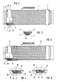
- FIG. 1 The embodiment of an exhaust hose arrangement shown in FIG. 1 consists of an outer winding shaft hose or primarily a metal tube which surrounds an inner hose 2 at a distance of about 5 mm, which, as can be seen in particular from FIG. 2, has an agraff profile. While the seal is assigned to the relatively thin corrugated metal tube 1, since it has a leakage rate of zero, the inner tube 2 is adapted to the static requirements.
- the double hose has the flexibility required for exhaust pipes; the inner tube 2 with an agraff profile meets the static requirements.
- care must be taken that the agraff profile or the inner hose is used in such a way that the corrugated tube 1 remains in the elastic range even in the event of bends and does not lose its sealing property .
- the end connection 3 consists of a connecting sleeve 5 which engages with the cylindrical end section 6 in the agraff profile 2 and holds it from the inside.
- a cylindrical sleeve 7 is pushed over the corrugated hose 2 and is connected to the part 5 by means of a weld seam 8.
- the agraff profile or the inner tube 3 is held by pressing the two approximately parallel cylindrical sections.
- the corrugated tube 1 is pushed onto the sleeve 7, which in turn is held in the operative position by a ring.
- the ring 10 has an internal thread if the outer tube is designed as a winding tube. On the other hand, it can have ribs that run parallel to one another if it is a corrugated pipe. In any case, the corrugations of the ring 10 hold the outer tube.
- the ring 10 is connected to the end connection by a weld 11.
- the same construction of the end connection is provided in mirror image.
- the outer tube 12 has an agraff profile, while the inner tube 13 has a reinforced agraff profile.
- the end connection 14 in turn consists of a connecting sleeve with a cylindrical section 15, on which the agraff profile 13 is held in a press fit by means of a ring 16.
- the agraff profile 12 that is to say the outer tube, is also held in the present case by a ring 17 in an interference fit on the ring 16. Both rings are firmly connected to the end connection by annular weld seams 18 and 19, respectively.
- 5 is a modified end connection, which can also be used when only a single hose is to be held. However, this embodiment is described as a holder for two hoses lying one above the other.
- a reinforced agraff profile 21 is placed as an inner tube and held in a press fit via a cylindrical ring 22.
- the outer tube 23 - in the present case designed as a corrugated tube - is surrounded on its free edge by a round metal ring 24 which is connected to the cylindrical ring 22 by means of a weld seam 25.
- a weld seam 26 holds the cylindrical ring together with the connecting sleeve.
- the metal hose arrangement according to the invention which is particularly suitable for motor vehicle exhaust pipes, can also be used for similar purposes. If e.g. soundproofing should be provided, it is possible to cover the space between the two hoses with a soundproofing material, e.g. a substitute for asbestos or rock wool. It is obvious “that the connection connections can be designed differently and be adapted to the actual structural requirements; it is also possible that flame pipes, damping elements or the like protrude into the end connection.
- the metal hose arrangement - provided that it is of course used for exhaust gas purposes - must also be suitably heat-resistant, the choice of the manufacturing material must be made accordingly.
Landscapes
- Engineering & Computer Science (AREA)
- General Engineering & Computer Science (AREA)
- Mechanical Engineering (AREA)
- Chemical & Material Sciences (AREA)
- Combustion & Propulsion (AREA)
- Exhaust Silencers (AREA)
- Rigid Pipes And Flexible Pipes (AREA)
Applications Claiming Priority (2)
| Application Number | Priority Date | Filing Date | Title |
|---|---|---|---|
| DE3804208 | 1988-02-11 | ||
| DE3804208A DE3804208A1 (de) | 1988-02-11 | 1988-02-11 | Metallschlauchanordnung, insbesondere wickel- oder wellschlauchanordnung fuer kraftfahrzeugabgasleitungen |
Publications (2)
| Publication Number | Publication Date |
|---|---|
| EP0328138A2 true EP0328138A2 (fr) | 1989-08-16 |
| EP0328138A3 EP0328138A3 (fr) | 1991-07-03 |
Family
ID=6347172
Family Applications (1)
| Application Number | Title | Priority Date | Filing Date |
|---|---|---|---|
| EP19890102351 Withdrawn EP0328138A3 (fr) | 1988-02-11 | 1989-02-10 | Arrangement de tuyau en matière métallique en particulier arrangement de tuyau ondulé ou enroule pour tuyauterie d'échappement automobiles |
Country Status (2)
| Country | Link |
|---|---|
| EP (1) | EP0328138A3 (fr) |
| DE (1) | DE3804208A1 (fr) |
Cited By (1)
| Publication number | Priority date | Publication date | Assignee | Title |
|---|---|---|---|---|
| EP0503369A1 (fr) * | 1991-03-09 | 1992-09-16 | Witzenmann GmbH Metallschlauch-Fabrik Pforzheim | Elément de connexion des extrémités des deux tuyaux d'un système, d'échappement pour véhicules |
Families Citing this family (4)
| Publication number | Priority date | Publication date | Assignee | Title |
|---|---|---|---|---|
| DE4202808C2 (de) * | 1992-01-31 | 1996-10-02 | Westfalia Metallformtechnik Gm | Verfahren zum Herstellen eines Leitungselements und Vorrichtung zur Durchführung des Verfahrens |
| US7571745B2 (en) | 2004-05-28 | 2009-08-11 | Westfalia Metallschlauchtechnik Gmbh & Co. Kg | Exhaust-gastight decoupling element from stripwound hoses |
| DE102004026705B4 (de) * | 2004-05-28 | 2006-04-13 | Westfalia Metallschlauchtechnik Gmbh & Co. Kg | Abgasdichtes Entkopplungselement aus Wickelschläuchen |
| DE102005048479A1 (de) * | 2005-10-07 | 2007-04-12 | Westfalia Metallschlauchtechnik Gmbh & Co. Kg | Metallschlauchanordnung mit Innen- und Außenschlauch |
Family Cites Families (9)
| Publication number | Priority date | Publication date | Assignee | Title |
|---|---|---|---|---|
| DE76745C (de) * | H. WITZEN MANN in Pforzheim | Metall-Doppelschlauch mit entKlasse -. gegengesetzten Windungen | ||
| AT8691B (de) * | 1898-08-17 | 1902-08-11 | Emil Witzenmann | Biegsames Metallrohr mit biegsamem, aus einem Metallspiralschlauch bestehendem Schutzmantel. |
| AT8692B (de) * | 1900-04-07 | 1902-08-11 | Emil Witzenmann | Biegsames Metallrohr mit biegsamem Schutzmantel. |
| DE2150580A1 (de) * | 1971-10-11 | 1973-04-19 | Westerbarkey Westaflex | Rohrleitung aus rillenrohr |
| DE2332600A1 (de) * | 1973-06-27 | 1975-01-16 | Hans Skodock Spezialfabrik Fue | Flexibler metallschlauch |
| DE2705361B2 (de) * | 1977-02-09 | 1979-03-29 | Metallschlauch-Fabrik Pforzheim (Vorm. Hch. Witzenmann) Gmbh, 7530 Pforzheim | Schwimmfähige Schlauchleitung |
| JPS61107912U (fr) * | 1984-12-19 | 1986-07-09 | ||
| DE3447270A1 (de) * | 1984-12-22 | 1986-07-10 | Witzenmann GmbH, Metallschlauch-Fabrik Pforzheim, 7530 Pforzheim | Metallschlauch in form eines wellschlauches oder wickelschlauches mit schraubengangfoermig verlaufender wellung bzw. wicklung |
| DE3546049A1 (de) * | 1985-12-24 | 1987-06-25 | Witzenmann Metallschlauchfab | Agraffschlauch mit vieleckigem querschnitt |
-
1988
- 1988-02-11 DE DE3804208A patent/DE3804208A1/de active Granted
-
1989
- 1989-02-10 EP EP19890102351 patent/EP0328138A3/fr not_active Withdrawn
Cited By (1)
| Publication number | Priority date | Publication date | Assignee | Title |
|---|---|---|---|---|
| EP0503369A1 (fr) * | 1991-03-09 | 1992-09-16 | Witzenmann GmbH Metallschlauch-Fabrik Pforzheim | Elément de connexion des extrémités des deux tuyaux d'un système, d'échappement pour véhicules |
Also Published As
| Publication number | Publication date |
|---|---|
| EP0328138A3 (fr) | 1991-07-03 |
| DE3804208C2 (fr) | 1990-09-27 |
| DE3804208A1 (de) | 1989-08-24 |
Similar Documents
| Publication | Publication Date | Title |
|---|---|---|
| DE69216282T4 (de) | Flexible Kupplungseinrichtung | |
| EP0856648B1 (fr) | Elément de conduite flexible pour conduites de gaz d'échappement | |
| EP0615595B1 (fr) | Dispositif de raccordement flexible pour deux elements tubulaires, notamment pour systemes de gaz d'echappement de vehicules | |
| DE4303950C1 (de) | In einem inneren und einem äußeren Mantelrohr gehalterter metallischer Wabenkörper, insbesondere Katalysator-Trägerkörper | |
| EP0580963B1 (fr) | Conduite articulée | |
| EP0208128B1 (fr) | Connexion articulée d'éléments de tube, notamment dans des conduits d'échappement de véhicules automobiles | |
| DE3610684A1 (de) | Gelenkige verbindung von rohrteilen, insbesondere bei abgasleitungen von kraftfahrzeugen | |
| DE2650937B2 (de) | Kältemaschine mit federnd in einer Kapsel gehaltenem Motorverdichter | |
| DE102007016149A1 (de) | Metallschlauchanordnung mit Innen- und Außenschlauch | |
| EP0681097B1 (fr) | Elément de connexion flexible pour éléments tubulaires | |
| EP1048881B1 (fr) | Conduite de produit réfrigérant pour conditionneurs d'air | |
| EP0573764B1 (fr) | Joint articulé d'éléments de tube, notamment dans des conduits d'échappement de véhicules automobiles | |
| DE29509434U1 (de) | Entkopplungselement für Schwingungen in Rohrleitungen | |
| DE3702243A1 (de) | Flexible abgasleitung fuer kraftfahrzeuge | |
| EP2045451A2 (fr) | Dispositif d'isolation d'un compensateur | |
| DE29611142U1 (de) | Entkopplungselement für Schwingungen in Rohrleitungen | |
| EP0575727A1 (fr) | Joint de tuyau | |
| DE3922667C2 (de) | Vorrichtung zur katalytischen Entgiftung zur Entrußung und/oder zur Schalldämpfung von Verbrennungsmotor-Abgasen mit doppelwandigem Gehäuse | |
| DE3804208C2 (fr) | ||
| DE2529508C3 (de) | Ringgewellter Schlauch oder Balg | |
| DE202007004757U1 (de) | Entkoppelelement mit Isolation | |
| DE3427364A1 (de) | Gelenkartige verbindungen fuer abgasleitungen | |
| DE69600074T2 (de) | Flexibles röhrenförmiges Verbindungselement, für die Abgasanlage eines Kraftfahrzeuges | |
| DE2734983A1 (de) | Auspuffleitung fuer eine ein fahrzeug antreibende brennkraftmaschine | |
| DE69713018T2 (de) | Entkupplungsvorrichtung, die zwischen zwei Rohrleitungsabschnitte eingesetzt werden kann |
Legal Events
| Date | Code | Title | Description |
|---|---|---|---|
| PUAI | Public reference made under article 153(3) epc to a published international application that has entered the european phase |
Free format text: ORIGINAL CODE: 0009012 |
|
| AK | Designated contracting states |
Kind code of ref document: A2 Designated state(s): CH FR GB IT LI NL SE |
|
| PUAL | Search report despatched |
Free format text: ORIGINAL CODE: 0009013 |
|
| AK | Designated contracting states |
Kind code of ref document: A3 Designated state(s): CH FR GB IT LI NL SE |
|
| 17P | Request for examination filed |
Effective date: 19911230 |
|
| 17Q | First examination report despatched |
Effective date: 19920514 |
|
| STAA | Information on the status of an ep patent application or granted ep patent |
Free format text: STATUS: THE APPLICATION HAS BEEN WITHDRAWN |
|
| 18W | Application withdrawn |
Withdrawal date: 19920729 |