EP0328149A2 - Dispositif pour la représentation de l'écriture braille - Google Patents
Dispositif pour la représentation de l'écriture braille Download PDFInfo
- Publication number
- EP0328149A2 EP0328149A2 EP89102377A EP89102377A EP0328149A2 EP 0328149 A2 EP0328149 A2 EP 0328149A2 EP 89102377 A EP89102377 A EP 89102377A EP 89102377 A EP89102377 A EP 89102377A EP 0328149 A2 EP0328149 A2 EP 0328149A2
- Authority
- EP
- European Patent Office
- Prior art keywords
- carrier
- feeler pins
- feeler
- pins
- locking elements
- Prior art date
- Legal status (The legal status is an assumption and is not a legal conclusion. Google has not performed a legal analysis and makes no representation as to the accuracy of the status listed.)
- Granted
Links
- 238000005452 bending Methods 0.000 claims abstract description 23
- 230000006835 compression Effects 0.000 claims description 5
- 238000007906 compression Methods 0.000 claims description 5
- 239000000969 carrier Substances 0.000 claims description 3
- 239000011152 fibreglass Substances 0.000 claims description 2
- 230000001154 acute effect Effects 0.000 claims 1
- NJPPVKZQTLUDBO-UHFFFAOYSA-N novaluron Chemical compound C1=C(Cl)C(OC(F)(F)C(OC(F)(F)F)F)=CC=C1NC(=O)NC(=O)C1=C(F)C=CC=C1F NJPPVKZQTLUDBO-UHFFFAOYSA-N 0.000 description 4
- 238000007639 printing Methods 0.000 description 4
- 238000010276 construction Methods 0.000 description 3
- 230000002349 favourable effect Effects 0.000 description 2
- 229910000831 Steel Inorganic materials 0.000 description 1
- 241001422033 Thestylus Species 0.000 description 1
- 230000000712 assembly Effects 0.000 description 1
- 238000000429 assembly Methods 0.000 description 1
- 230000000903 blocking effect Effects 0.000 description 1
- 229910010293 ceramic material Inorganic materials 0.000 description 1
- 239000004020 conductor Substances 0.000 description 1
- 230000000694 effects Effects 0.000 description 1
- 238000005516 engineering process Methods 0.000 description 1
- 230000005284 excitation Effects 0.000 description 1
- 230000007257 malfunction Effects 0.000 description 1
- 239000012528 membrane Substances 0.000 description 1
- 239000002184 metal Substances 0.000 description 1
- 238000000034 method Methods 0.000 description 1
- 238000005192 partition Methods 0.000 description 1
- 239000004033 plastic Substances 0.000 description 1
- 229920003023 plastic Polymers 0.000 description 1
- 230000000717 retained effect Effects 0.000 description 1
- 238000005476 soldering Methods 0.000 description 1
- 239000010959 steel Substances 0.000 description 1
- 238000004804 winding Methods 0.000 description 1
Images



Classifications
-
- G—PHYSICS
- G09—EDUCATION; CRYPTOGRAPHY; DISPLAY; ADVERTISING; SEALS
- G09B—EDUCATIONAL OR DEMONSTRATION APPLIANCES; APPLIANCES FOR TEACHING, OR COMMUNICATING WITH, THE BLIND, DEAF OR MUTE; MODELS; PLANETARIA; GLOBES; MAPS; DIAGRAMS
- G09B21/00—Teaching, or communicating with, the blind, deaf or mute
- G09B21/02—Devices for Braille writing
Definitions
- the invention relates to a device for displaying braille according to the preamble of claim 1.
- the arrangement requires a relatively large height and allows only a limited modular structure.
- the bending strips which run essentially parallel to the axis of the feeler pins, are exposed to a high kink load, which can easily lead to breakage and therefore to annoying malfunctions in the sensitive ceramic material.
- Electromechanical drive or release devices have also been proposed to either bring spring-loaded feeler pins to the raised position or to hold them.
- DE-A-2 364 342 shows a module arrangement with magnetic cores or anchors located under the feeler pins, which can be raised by means of individually controlled magnetic coils.
- a mechanical lock is provided for holding, which can be displaced transversely to the axial direction of the cores and the feeler pins with a larger locking magnet against a leaf spring.
- the space requirement of the electromagnets and their mutual influence complicates the realization of this construction, which moreover builds quite high and only provides the cross bar for supporting raised pins, which is hardly suitable for absorbing larger forces - such as for printing set patterns.
- An important aim of the invention is to improve a device of the type mentioned at the outset with simple and economical means in such a way that the flatest possible structure of selectable surface area can be created so that a desired lettering field size can be produced on a case-by-case basis. Furthermore, the invention aims to provide an operationally reliable arrangement with few components, which can be used as a reader or for printing set patterns as required.
- the invention is characterized in that the device is composed of modules, each of which consists of an upper part guiding the feeler pins and a height-adjustable lower support which has the lifting or lowering device for the feeler pins or forms itself.
- the movable carrier holds or forms the lifting and lowering device for the feeler pins, which can therefore be set in a simple manner. A set pattern can only be deleted by changing the height of the beam; however, as long as it remains in its position, a set pattern remains.
- the module structure enables the creation of text fields of the desired size by simply lining up the individual elements, which can be made quite flat.
- the device is robust and can also be used permanently for printing purposes.
- the carrier is movably mounted on or in the upper part and in particular can be pivoted at least at a small angle.
- the position of the carrier relative to the upper part can expediently be adjusted by means of an eccentric. This can be done by hand or by motor, for example by means of a crank, a stepper motor or the like.
- a favorable further development consists according to claim 4 in that the carrier has pedestals which are assigned to the bottom surfaces of the feeler pins and which face the cover plate of the upper part essentially parallel. If the carrier is lowered, the feeler pins with their bottom surfaces on the pedestals slide back in their cover plate guide. In each case two adjacent feeler pins can be supported on the same platform level. It is particularly expedient if, according to claim 6, a number of platforms, in particular four, are arranged in a step-like manner at one end of the carrier. One then uses feeler pins of correspondingly different lengths, namely in four lengths, so that a uniform overhang of the tips of raised feeler pins can be achieved with respect to the outer surface of the cover plate.
- a bushing or double bushing leading the lower end of the supported feeler pin or pair of feeler pins is arranged above each platform.
- the latter are expediently widened according to claim 8, especially weakly conical, to promote the mobility of the stylus when changing the winding due to the pivoting of the carrier.
- the carrier simultaneously holds the locking and unlocking device. Additional elements are therefore not required. Rather, channels or grooves can be present in the carrier at the same height as the platforms, which hold and / or guide locking elements running transversely to the bushings. Such a structure is extremely simple and can be realized with very small dimensions, so that the modules can be made correspondingly narrow and flat. As a result, the device according to the invention is very compact.
- the front ends of the locking elements can each be moved at least up to below the axis of the associated socket, so that each sensor pin in the raised position at least on half of its bottom surface is supported.
- the locking elements are anchor tappets, which are loaded by springs towards the platforms and can be retracted against the spring force by means of magnetic coils.
- the magnetic coils and the springs can be attached according to claim 14 in the channels or grooves of the carrier.
- Adjacent magnetic coils can be used with opposite poles, which makes magnetic inferences easy. Since the magnetic coils are arranged transversely to the direction of movement of the feeler pins, in contrast to conventional technology, considerable savings are made in terms of overall height.
- a preferred embodiment of the invention for which independent protection is claimed, provides according to claim 15 that the locking elements are in particular piezoceramic bending strips, the free ends of which can be pivoted in from the side under the respectively assigned bushings and can be pivoted away from them to the side .
- the locking elements are in particular piezoceramic bending strips, the free ends of which can be pivoted in from the side under the respectively assigned bushings and can be pivoted away from them to the side .
- Such an arrangement has the great advantage that the bending strips even elastic elements and special springs are therefore unnecessary. This contributes significantly to increased operational reliability and also makes very small dimensions possible.
- a bending strip e.g. bimetallic elements can also be used according to the invention, preferably piezoceramic strips are used which respond very quickly and do not generate or have to be dissipated when they are actuated.
- the measure of claim 16 ensures on the one hand low susceptibility to breakage and on the other hand high susceptibility to breakage Pressure resistance of the styli. It is also possible to get by with a small travel range, and that without bending the bending strips.
- the locking elements are expediently provided with electrical connections at their rear ends. This enables the magnet coils or piezoceramic bending strips or the like. supply the control or operating voltage in a simple manner. Since the locking elements sit in the channels or grooves of the wearer, the ends can run freely and e.g. by soldering lugs, wires or the like. continue. It contributes to the stability of the arrangement if the bending strips are mechanically fixed with their connecting ends in the channels or grooves. This also increases the contact security, since there is no movement at the connections themselves.
- the invention further provides according to claim 19 that the carrier holds a control board conductively connected to the electrical connections. As a result, there are no relative movements on the carrier to control the individual locking elements.
- flexible conductors can lead to another circuit board or electrical circuit board which, according to claim 20, is attached to the upper part for the power supply.
- the fixed wiring possible there allows conventional connecting elements to be provided which are used for the electrical connection of the modules to one another and to a control part.
- feeler pins can be formed in one piece, for example from glass fiber reinforced plastic. Cylindrical pins with only one flange are sufficient. However, it should be noted that metal pins are also suitable according to the invention.
- each module has side walls with a bearing bore which receives an axis or shaft holding the carrier.
- the axis or shaft can be designed according to claim 24 as a flattened eccentric, which is seated in a bearing recess of the carrier and has at least one approximately flat contact surface.
- This arrangement allows the height of the carrier to be adjusted in a very simple manner. If necessary, the point height of the pens can be adapted to special requests.
- a stop for limiting the change in height of the carrier is expediently arranged on the carrier and / or on the upper part.
- the carrier is spring-loaded according to claim 26, especially towards the upper part.
- a restoring force acts which only needs to be released in order to bring about a desired countermovement of the wearer.
- the invention provides according to claim 27 that the modules of the device have a common leaf spring, which acts on all carriers. Therefore, each individual pin is supported on the carrier particularly firmly and can withstand high loads accordingly. At the same time, it is ensured that the individual locking elements of the pins set are loaded only slightly.
- the module shown in FIGS. 1 and 2, generally designated 10, consists of an upper part 12 and a carrier 30 which - as indicated schematically in FIG. 1 by a double arrow - is movable up and down relative to the upper part.
- a rod holder 46 can be provided, which can be moved in height by a mechanism (not shown).
- the upper part 12 has a cover plate 14, in which feeler pins 18 are guided, in parallel bores.
- the feeler pins 18 have crests 20 which, in the raised position of the feeler pins 18, protrude beyond the outer surface 16, but disappear in the cover plate 14 in the lowered position of the feeler pins 18.
- the feeler pins 18 each have a flange 22 on which a compression spring 24 is supported, which surrounds the feeler pin 18 in the upper region and on the inner surface of the cover plate 14 you find abutment.
- the flanges 22 can rest on a holder plate 28 embedded in the cover plate 14 at the bottom.
- the feeler pins 18 continue in predetermined lengths. Their bottom surfaces 26 can come to rest on pedestals 32 of the carrier 30.
- the feeler pins 18 are guided vertically in bushings 34 of the carrier 30.
- the guide bores arranged therein are vertical for the feeler pins 18 and thus for these themselves.
- the bushes 34 are arranged vertically in the carrier 30.
- the platforms 32 and the channels or grooves 36 with the same height in the carrier 30 run horizontally, that is to say transversely to the feeler pins 18.
- Magnetic coils 38 are located in the channels or grooves 36, preferably with alternating opposite polarity.
- Armature plungers 40 are axially movable in the interior of the magnet coils 38, which are supported with springs 42 at one end of the channels or grooves 36, where the connections 52 of the magnet coils 38 are also arranged.
- the springs 42 load the armature plungers 40 towards the respectively assigned feeler pins 18.
- the channels or grooves 36 in the support 30 form a step-like arrangement and are staggered so that each anchor plunger can penetrate into an associated socket 34 and find its stop therein. If the carrier 30 is now lowered relative to the upper part 12, the flanges 22 of the feeler pins 18 come to bear on the holding plate 28, while the bottom surface 26 of the feeler pins 18 stands out from the support surface in the bracket 30. With sufficient lowering, the compression springs 42 push the anchor plunger 40 forward, ie in each case under the bottom surface 26 of the associated feeler pin 18. When the support 30 is then lifted, all the feeler pins 18 protrude with their crests 20 over the outer surface 16 of the upper part 12.
- an upper part 12 of the module 10 is stationary and a carrier 30 arranged underneath it is vertically movable, as indicated by the double arrow in FIG. 3.
- cylindrical feeler pins 18 are used, which are guided in the upper area with resilient support in the cover plate 14 and in the holding plate 28 so as to be vertically movable. Flanges 22 of the feeler pins 18 can be supported on the latter.
- FIGS. 3 and 4 corresponds to that of FIGS. 1 and 2, but here magnetic coils 38 lie opposite one another in channels 36 of the carrier 30 on the same level. Accordingly, the assigned platforms 32 are also of equal height to one another. It can be seen that in this embodiment a four-point drawing field 48 (FIG. 4) with two pairs of magnets on either side of the four feeler pins 18 is sufficient. Otherwise, the function corresponds to that described above. If a feeler pin 18 is to be fully lowered (left in FIG. 3) so that its bottom surface 26 rests on the pedestal 32, the magnet coil 38 in question is excited and the armature tappet 40 is thereby withdrawn against spring force.
- the compression spring 42 presses the anchor plunger 40 forward so that it projects into the bush 34 and strikes there, provided that the carrier 30th was sufficiently lowered from the upper part 12. If the carrier 30 is then raised, the bottom surface 26 of the relevant stylus 18 comes to rest on the front end of the advanced anchor plunger 40, so that the pin is raised and its tip 20 projects beyond the outer surface 16.
- FIGS. 3 and 4 are suitable for line construction with four-point character fields 48, while the embodiment of FIGS. 1 and 2 - with a somewhat greater overall height - is suitable and intended for the representation of eight-point characters (FIG. 2).
- piezoceramic bending strips 50 which are fixed in the channels 36 of the carrier 30 at the ends provided with connections 52, serve as locking elements (FIG. 6).
- a bending strip 50 rests at rest (on the right in FIGS. 5 and 6) on an inner partition wall of the carrier 30, and a sensing pin 18 is supported with its bottom surface 26 on the free end of this bending strip 50, so that the sensing pin 18 is raised and its tip 20 protrudes over the outer surface 16 of the upper part 12. If electrical voltage is now applied, the state shown in FIGS. 5 and 6 arises.
- the bending strip 50 bends out of its plane and thereby swivels with its free end to the side, whereby the feeler pin 18 in question lowers under the pressure of its spring 24 until the flange 22 strikes the holding plate 28.
- a holding edge 44 of the upper part 12 can serve to fix it on a housing (not shown).
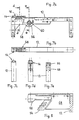
- FIGS. 7a to 7e and FIG. 8 show a further practical embodiment of modules for a device according to the invention.
- the upper part 12 is shown in FIGS. 7a to 7e and FIG. 8, whose cover plate 14 protrudes somewhat upwards here, so that the outer surface 16 with the drawing field 48 lies higher than the other sections of the upper part 12.
- This can be a plastic injection-molded part with side walls 56, in which a bearing bore 58 is present.
- a number of small bores are provided, through which a screw connection, pinning or the like. is possible.
- a free area of the upper part 12 can accommodate a printed circuit board 68 inside or below (FIG. 8), which serves to supply power to a control board 54, which is attached to the associated carrier 30.
- Such a carrier 30 is shown in FIGS. 9a to 9d. It has a bearing recess 62 in an upper region, into which an axis or shaft 60 serving as an eccentric and flattened on one side can be inserted, as indicated in FIGS. 7a and 9a with a schematic cross section. The carrier 30 can then be moved about the axis or shaft 60 until an end designed as a stop 66 arrives at the upper part 12 on the inside. In view of the short travel distances required for lowering or raising the feeler pins 18, a slight pivoting of the carrier 30 is sufficient.
- FIG. 9a and 9b; 10a This is designed in a step-like manner on a front part (FIGS. 9a and 9b; 10a) and is provided with channels 36 which each run horizontally and at the same height with a platform 32.
- a bushing 34 is arranged above the latter, which guides the lower end of the associated feeler pin 18 and is expediently flared upwards in order to ensure its mobility despite the change in the angle of the carrier 30.
- the carrier 30 has a recess for the control board 54 fixedly connected to it (FIGS. 9a and 8). From this, flexible lines (not shown) can lead to the printed circuit board 68, which is provided for the power supply.
- FIGS. 10a and 10b show the support and guide arrangement for the feeler pins 18 on an enlarged scale
- FIGS. 11 and 12 show how piezoceramic bending strips 50, which are arranged upright in the channels or grooves 36 of the carrier 30, and effect unlocking.
- a bending strip 50 is shown at the top in FIG. 11 and at the left in FIG. 12, which grips under and supports the bottom surface of the feeler pin 18 which is in the raised position.
- the lower half of FIG. 11 and the right half of FIG. 12 show an unlocked position, in which the respective feeler pin 18 is lowered after the associated bending strip 50 has been moved to the side under the feeler pin 18 by the application of tension.
- the device according to the invention can be designed comfortably in the way often preferred by blind people, according to which only those signs or points are set which are also intended to immediately convey information, while the reading surface 16 remains empty (so that the crests 20 of the retracted feeler pins 18 are not palpable).
- the module structure creates a very simple and therefore inexpensive reading device for blind people who e.g. for displaying numbers on clocks, thermometers etc., but also for longer texts. If desired, line displays can also be used for printing.
- the control takes place electronically, preferably via a microprocessor, and the power supply can take place via a power supply unit or also with battery supply.
- the carrier 30 is moved, which, thanks to its special design, can be carried out in a flat design and with a low weight.
- the locking elements 38, 40; 50 across the feeler pins 18 so that their locking and unlocking is fast and stable.
- only a few components are required, which can also be assembled into assemblies of any size or small size.
- feeler pins 18 In the fixed upper part 12, lowered feeler pins 18 come to rest with their flange 22 on the holding plate 28. This absorbs the compressive forces of the springs 24 when the carrier 30 is lifted down. Then the locking elements 40, 50 can be actuated and actuated practically without load, shortly before the carrier 30 is raised again to set the desired pattern. This advantage is also retained if feeler pins 18 are used without spring loading, which is easily possible, for example, in the exemplary embodiment of FIGS. 7 to 12, because the pins themselves assume the lowest position under their own weight.
Landscapes
- Engineering & Computer Science (AREA)
- Educational Administration (AREA)
- General Health & Medical Sciences (AREA)
- Business, Economics & Management (AREA)
- Physics & Mathematics (AREA)
- Audiology, Speech & Language Pathology (AREA)
- Health & Medical Sciences (AREA)
- Educational Technology (AREA)
- General Physics & Mathematics (AREA)
- Theoretical Computer Science (AREA)
- User Interface Of Digital Computer (AREA)
- Toys (AREA)
- Devices For Indicating Variable Information By Combining Individual Elements (AREA)
- Printers Characterized By Their Purpose (AREA)
Applications Claiming Priority (2)
| Application Number | Priority Date | Filing Date | Title |
|---|---|---|---|
| DE8801823U | 1988-02-12 | ||
| DE8801823U DE8801823U1 (de) | 1988-02-12 | 1988-02-12 | Vorrichtung zum Darstellen von Blindenschrift |
Publications (3)
| Publication Number | Publication Date |
|---|---|
| EP0328149A2 true EP0328149A2 (fr) | 1989-08-16 |
| EP0328149A3 EP0328149A3 (fr) | 1992-08-05 |
| EP0328149B1 EP0328149B1 (fr) | 1994-11-09 |
Family
ID=6820612
Family Applications (1)
| Application Number | Title | Priority Date | Filing Date |
|---|---|---|---|
| EP89102377A Expired - Lifetime EP0328149B1 (fr) | 1988-02-12 | 1989-02-11 | Dispositif pour la représentation de l'écriture braille |
Country Status (2)
| Country | Link |
|---|---|
| EP (1) | EP0328149B1 (fr) |
| DE (2) | DE8801823U1 (fr) |
Cited By (4)
| Publication number | Priority date | Publication date | Assignee | Title |
|---|---|---|---|---|
| CN101853592A (zh) * | 2010-05-17 | 2010-10-06 | 南京信息职业技术学院 | 盲文凹凸点控制结构及逐行驱动全页盲文点显器 |
| CN104408994A (zh) * | 2014-11-11 | 2015-03-11 | 浙江理工大学 | 分层电磁式的盲文显示装置及盲文阅读机 |
| CN111462592A (zh) * | 2020-05-09 | 2020-07-28 | 长春大学 | 一种压电弹片式盲文点显装置 |
| CN111752408A (zh) * | 2020-06-03 | 2020-10-09 | 清华大学 | 触觉显示装置 |
Families Citing this family (2)
| Publication number | Priority date | Publication date | Assignee | Title |
|---|---|---|---|---|
| DE19746617A1 (de) * | 1997-10-22 | 1999-05-06 | Gunnar Matschulat | Vorrichtung zur Darstellung taktiler Informationen |
| CN110969915B (zh) * | 2019-12-24 | 2024-09-17 | 北京红点互联技术研发有限公司 | 盲文显示模块及盲文显示装置 |
Family Cites Families (5)
| Publication number | Priority date | Publication date | Assignee | Title |
|---|---|---|---|---|
| FR2408879A1 (fr) * | 1977-11-10 | 1979-06-08 | Cii Honeywell Bull | Dispositif de conversion de signaux electriques numeriques representatifs de caracteres en une representation par points auto-verrouillee, du type braille par exemple |
| GB1595894A (en) * | 1977-11-18 | 1981-08-19 | Clark & Smith Ind Ltd | Display devices |
| US4266936A (en) * | 1978-11-06 | 1981-05-12 | Leonard Rose | Braille display reader |
| ATE38575T1 (de) * | 1985-12-11 | 1988-11-15 | Blindenstudienanstalt Deutsche | Vorrichtung zum darstellen von grafischer information. |
| NL8600453A (nl) * | 1986-02-24 | 1987-09-16 | Tieman F J Bv | Op de tastzin werkende weergeefinrichting en werkwijze voor de vervaardiging daarvan. |
-
1988
- 1988-02-12 DE DE8801823U patent/DE8801823U1/de not_active Expired
-
1989
- 1989-02-11 DE DE58908614T patent/DE58908614D1/de not_active Expired - Fee Related
- 1989-02-11 EP EP89102377A patent/EP0328149B1/fr not_active Expired - Lifetime
Cited By (5)
| Publication number | Priority date | Publication date | Assignee | Title |
|---|---|---|---|---|
| CN101853592A (zh) * | 2010-05-17 | 2010-10-06 | 南京信息职业技术学院 | 盲文凹凸点控制结构及逐行驱动全页盲文点显器 |
| CN104408994A (zh) * | 2014-11-11 | 2015-03-11 | 浙江理工大学 | 分层电磁式的盲文显示装置及盲文阅读机 |
| CN104408994B (zh) * | 2014-11-11 | 2017-01-11 | 浙江理工大学 | 分层电磁式的盲文显示装置及盲文阅读机 |
| CN111462592A (zh) * | 2020-05-09 | 2020-07-28 | 长春大学 | 一种压电弹片式盲文点显装置 |
| CN111752408A (zh) * | 2020-06-03 | 2020-10-09 | 清华大学 | 触觉显示装置 |
Also Published As
| Publication number | Publication date |
|---|---|
| EP0328149B1 (fr) | 1994-11-09 |
| DE58908614D1 (de) | 1994-12-15 |
| EP0328149A3 (fr) | 1992-08-05 |
| DE8801823U1 (de) | 1989-03-09 |
Similar Documents
| Publication | Publication Date | Title |
|---|---|---|
| DE2121886C2 (de) | Siebdruckmaschine | |
| DE1635848C3 (de) | Mustervorrichtung für Rundstrickmaschinen mit umlaufenden Nadelträgern | |
| DE19844428B4 (de) | Prüfsonde für einen Fingertester, ein Verfahren zum Ansteuern einer Prüfsonde, Fingertester zum Prüfen von Leiterplatten und ein Verfahren zum Prüfen von Leiterplatten mit einem Fingertester | |
| EP0278073B1 (fr) | Sonde pour un adaptateur pour un dispositif d'essai de cartes imprimées | |
| EP2855311B1 (fr) | Imprimante dotée d'un dispositif de séparation | |
| EP0328149B1 (fr) | Dispositif pour la représentation de l'écriture braille | |
| DE69702128T2 (de) | Elektro-magnetische vorrichtung zum automatisch steuern der nadeln eines jacquard-mechanismus | |
| DE4028390C2 (de) | Elektromagnetisch arbeitende Jacquard-Steuervorrichtung | |
| EP0149055A2 (fr) | Dispositif pour la production d'un champ de repères tactiles | |
| DE102006053423A1 (de) | Relais | |
| DE3929275C1 (en) | Tactile display unit for blind people - has groups of projecting pegs forming Braille symbols | |
| WO1992015079A1 (fr) | Dispositif pour la constitution de structures superficielles variables | |
| DE2812380A1 (de) | Praegemaschine | |
| DE2734886C3 (de) | Bistabile Vorrichtung zur Darstellung wenigstens eines Punktes einer taktilen Information | |
| EP0082975A1 (fr) | Dispositif d'affichage | |
| DE966761C (de) | Schalteinrichtung fuer markierungsgesteuerte Maschinen | |
| DE2123780B2 (de) | Kartensuchvorrichtung | |
| DE2450650C3 (de) | Vorrichtung zum Schlagen von Karten oder Papierbändern für Jacquardmaschinen von Webmaschinen | |
| DE2707362C2 (de) | Bistabile Vorrichtung zur Darstellung wenigstens eines Punktes einer taktilen Information | |
| AT525319B1 (de) | Vorrichtung und Verfahren zur Darstellung von tastbarer Information in Form von tastbaren und nicht-tastbaren Punkten | |
| DE2152361C3 (de) | Statischer Lochkartenleser | |
| DE2501712A1 (de) | Tafel zur darstellung von blindenschrift | |
| DE2754224A1 (de) | Elektromechanisches geraet zum einstellen und loeschen alphanumerischer zeichen und anderer symbole in blindenschrift | |
| DE824120C (de) | Elektromechanische Speichereinrichtung fuer Lochkartenmaschinen | |
| DE1436194C3 (de) | Sortiergerät für mit Randschlitzen und einem magnetisierbaren Bereich an einem Rand versehene Karteikarten sowie Karteikarte hierfür |
Legal Events
| Date | Code | Title | Description |
|---|---|---|---|
| PUAI | Public reference made under article 153(3) epc to a published international application that has entered the european phase |
Free format text: ORIGINAL CODE: 0009012 |
|
| AK | Designated contracting states |
Kind code of ref document: A2 Designated state(s): DE ES FR NL |
|
| PUAL | Search report despatched |
Free format text: ORIGINAL CODE: 0009013 |
|
| AK | Designated contracting states |
Kind code of ref document: A3 Designated state(s): DE ES FR NL |
|
| 17P | Request for examination filed |
Effective date: 19921024 |
|
| 17Q | First examination report despatched |
Effective date: 19930319 |
|
| RAP1 | Party data changed (applicant data changed or rights of an application transferred) |
Owner name: HOFFARTH, RAINER |
|
| GRAA | (expected) grant |
Free format text: ORIGINAL CODE: 0009210 |
|
| AK | Designated contracting states |
Kind code of ref document: B1 Designated state(s): DE ES FR NL |
|
| PG25 | Lapsed in a contracting state [announced via postgrant information from national office to epo] |
Ref country code: NL Effective date: 19941109 Ref country code: FR Effective date: 19941109 Ref country code: ES Free format text: THE PATENT HAS BEEN ANNULLED BY A DECISION OF A NATIONAL AUTHORITY Effective date: 19941109 |
|
| REF | Corresponds to: |
Ref document number: 58908614 Country of ref document: DE Date of ref document: 19941215 |
|
| EN | Fr: translation not filed | ||
| NLV1 | Nl: lapsed or annulled due to failure to fulfill the requirements of art. 29p and 29m of the patents act | ||
| PLBE | No opposition filed within time limit |
Free format text: ORIGINAL CODE: 0009261 |
|
| STAA | Information on the status of an ep patent application or granted ep patent |
Free format text: STATUS: NO OPPOSITION FILED WITHIN TIME LIMIT |
|
| 26N | No opposition filed | ||
| PGFP | Annual fee paid to national office [announced via postgrant information from national office to epo] |
Ref country code: DE Payment date: 19970419 Year of fee payment: 9 |
|
| PG25 | Lapsed in a contracting state [announced via postgrant information from national office to epo] |
Ref country code: DE Free format text: LAPSE BECAUSE OF NON-PAYMENT OF DUE FEES Effective date: 19981103 |