EP0328193A1 - Pneumatische Ventilbetätigungsvorrichtung - Google Patents
Pneumatische Ventilbetätigungsvorrichtung Download PDFInfo
- Publication number
- EP0328193A1 EP0328193A1 EP19890200225 EP89200225A EP0328193A1 EP 0328193 A1 EP0328193 A1 EP 0328193A1 EP 19890200225 EP19890200225 EP 19890200225 EP 89200225 A EP89200225 A EP 89200225A EP 0328193 A1 EP0328193 A1 EP 0328193A1
- Authority
- EP
- European Patent Office
- Prior art keywords
- piston
- valve
- air
- positions
- open
- Prior art date
- Legal status (The legal status is an assumption and is not a legal conclusion. Google has not performed a legal analysis and makes no representation as to the accuracy of the status listed.)
- Withdrawn
Links
Images


Classifications
-
- F—MECHANICAL ENGINEERING; LIGHTING; HEATING; WEAPONS; BLASTING
- F01—MACHINES OR ENGINES IN GENERAL; ENGINE PLANTS IN GENERAL; STEAM ENGINES
- F01L—CYCLICALLY OPERATING VALVES FOR MACHINES OR ENGINES
- F01L9/00—Valve-gear or valve arrangements actuated non-mechanically
- F01L9/20—Valve-gear or valve arrangements actuated non-mechanically by electric means
-
- F—MECHANICAL ENGINEERING; LIGHTING; HEATING; WEAPONS; BLASTING
- F01—MACHINES OR ENGINES IN GENERAL; ENGINE PLANTS IN GENERAL; STEAM ENGINES
- F01L—CYCLICALLY OPERATING VALVES FOR MACHINES OR ENGINES
- F01L9/00—Valve-gear or valve arrangements actuated non-mechanically
- F01L9/10—Valve-gear or valve arrangements actuated non-mechanically by fluid means, e.g. hydraulic
- F01L9/16—Pneumatic means
-
- F—MECHANICAL ENGINEERING; LIGHTING; HEATING; WEAPONS; BLASTING
- F01—MACHINES OR ENGINES IN GENERAL; ENGINE PLANTS IN GENERAL; STEAM ENGINES
- F01L—CYCLICALLY OPERATING VALVES FOR MACHINES OR ENGINES
- F01L13/00—Modifications of valve-gear to facilitate reversing, braking, starting, changing compression ratio, or other specific operations
- F01L13/0005—Deactivating valves
-
- F—MECHANICAL ENGINEERING; LIGHTING; HEATING; WEAPONS; BLASTING
- F02—COMBUSTION ENGINES; HOT-GAS OR COMBUSTION-PRODUCT ENGINE PLANTS
- F02D—CONTROLLING COMBUSTION ENGINES
- F02D13/00—Controlling the engine output power by varying inlet or exhaust valve operating characteristics, e.g. timing
- F02D13/02—Controlling the engine output power by varying inlet or exhaust valve operating characteristics, e.g. timing during engine operation
- F02D13/0203—Variable control of intake and exhaust valves
- F02D13/0215—Variable control of intake and exhaust valves changing the valve timing only
-
- F—MECHANICAL ENGINEERING; LIGHTING; HEATING; WEAPONS; BLASTING
- F02—COMBUSTION ENGINES; HOT-GAS OR COMBUSTION-PRODUCT ENGINE PLANTS
- F02D—CONTROLLING COMBUSTION ENGINES
- F02D13/00—Controlling the engine output power by varying inlet or exhaust valve operating characteristics, e.g. timing
- F02D13/02—Controlling the engine output power by varying inlet or exhaust valve operating characteristics, e.g. timing during engine operation
- F02D13/0261—Controlling the valve overlap
-
- F—MECHANICAL ENGINEERING; LIGHTING; HEATING; WEAPONS; BLASTING
- F02—COMBUSTION ENGINES; HOT-GAS OR COMBUSTION-PRODUCT ENGINE PLANTS
- F02D—CONTROLLING COMBUSTION ENGINES
- F02D13/00—Controlling the engine output power by varying inlet or exhaust valve operating characteristics, e.g. timing
- F02D13/02—Controlling the engine output power by varying inlet or exhaust valve operating characteristics, e.g. timing during engine operation
- F02D13/0269—Controlling the valves to perform a Miller-Atkinson cycle
-
- F—MECHANICAL ENGINEERING; LIGHTING; HEATING; WEAPONS; BLASTING
- F01—MACHINES OR ENGINES IN GENERAL; ENGINE PLANTS IN GENERAL; STEAM ENGINES
- F01L—CYCLICALLY OPERATING VALVES FOR MACHINES OR ENGINES
- F01L2201/00—Electronic control systems; Apparatus or methods therefor
-
- F—MECHANICAL ENGINEERING; LIGHTING; HEATING; WEAPONS; BLASTING
- F02—COMBUSTION ENGINES; HOT-GAS OR COMBUSTION-PRODUCT ENGINE PLANTS
- F02D—CONTROLLING COMBUSTION ENGINES
- F02D13/00—Controlling the engine output power by varying inlet or exhaust valve operating characteristics, e.g. timing
- F02D13/02—Controlling the engine output power by varying inlet or exhaust valve operating characteristics, e.g. timing during engine operation
- F02D2013/0296—Changing the valve lift only
-
- F—MECHANICAL ENGINEERING; LIGHTING; HEATING; WEAPONS; BLASTING
- F02—COMBUSTION ENGINES; HOT-GAS OR COMBUSTION-PRODUCT ENGINE PLANTS
- F02D—CONTROLLING COMBUSTION ENGINES
- F02D41/00—Electrical control of supply of combustible mixture or its constituents
- F02D41/0002—Controlling intake air
- F02D2041/001—Controlling intake air for engines with variable valve actuation
-
- Y—GENERAL TAGGING OF NEW TECHNOLOGICAL DEVELOPMENTS; GENERAL TAGGING OF CROSS-SECTIONAL TECHNOLOGIES SPANNING OVER SEVERAL SECTIONS OF THE IPC; TECHNICAL SUBJECTS COVERED BY FORMER USPC CROSS-REFERENCE ART COLLECTIONS [XRACs] AND DIGESTS
- Y10—TECHNICAL SUBJECTS COVERED BY FORMER USPC
- Y10T—TECHNICAL SUBJECTS COVERED BY FORMER US CLASSIFICATION
- Y10T137/00—Fluid handling
- Y10T137/8593—Systems
- Y10T137/86493—Multi-way valve unit
- Y10T137/86574—Supply and exhaust
- Y10T137/86582—Pilot-actuated
- Y10T137/86614—Electric
Definitions
- the present invention relates generally to a two position, straight line motion actuator and more particularly to a fast acting actuator which utilizes pneumatic energy against a piston to perform extremely fast transit times between the two positions.
- the invention utilizes a pair of control valves to gate high pressure air to the piston and latching magnets to hold the valves in their closed positions until a timed short term electrical energy pulse excites a coil around a magnet to partially neutralize the magnet's holding force and release the associated valve to move in response to high pressure air to an open position.
- Stored pneumatic gases accelerate the piston rapidly from one position to the other position.
- intermediate pressure air fills a chamber applying an opposing force on the piston to slow the piston.
- This actuator finds particular utility in opening and closing the gas exchange, i.e., intake or exhaust, valves of an otherwise conventional internal combustion engine. Due to its fast acting trait, the valves may be moved between full open and full closed positions almost immediately rather than gradually as is characteristic of cam actuated valves.
- the actuator mechanism may find numerous other applications such as in compressor valving and valving in other hydraulic or pneumatic devices, or as a fast acting control valve for fluidic actuators or mechanical actuators where fast controlled action is required such as moving items in a production line environment.
- REPULSION ACTUATED POTENTIAL ENERGY DRIVEN VALVE MECHANISM wherein a spring (or pneumatic equivalent) functions both as a damping device and as an energy storage device ready to supply part of the accelerating force to aid the next transition from one position to the other.
- a spring or pneumatic equivalent
- the power or working piston which moves the engine valve between open and closed positions is separated from the latching components and certain control valving structures so that the mass to be moved is materially reduced allowing much faster operation than in the above two identified applications.
- a bistable electronically controlled fluid powered transducer has an armature including an air powered piston which is reciprocable along an axis between first and second positions along with a control valve reciprocable along the same axis between open and closed positions.
- a magnetic latching arrangement functions to hold the control valve in the closed position while an electromagnetic arrangement may be energized to temporarily neutralize the effect of the permanent magnet latching arrangement to release the control valve to move from the closed position to the open position.
- Energization of the electromagnetic arrangement causes movement of the valve in one direction along the axis allowing fluid from a high pressure source to drive the armature in the opposite direction from the first position to the second position along the axis.
- the distance between the first and second positions of the armature is typically greater than the distance between the open and closed positions of the valve.
- a pneumatically powered valve actuator includes a valve actuator housing with a piston reciprocable inside the housing along an axis.
- the piston has a pair of oppositely facing primary working surfaces.
- a pair of air control valves are reciprocable along the same axis relative to both the housing and the piston between open and closed positions.
- a coil is electrically energized to selectively opening one of the air control valves to supply pressurized air to one of the primary working surfaces causing the piston to move.
- the piston cooperates with the just opened air control valve upon sufficient piston motion to modify the air pressure differential across that air control valve causing the air control valve to reclose.
- Each of the air control valve includes an air pressure responsive surface which urges the control valve, when closed, toward its open position and there may be an air vent located about midway between the extreme positions of piston reciprocation for dumping expanded air from the one primary working surface and removing the accelerating force from the piston.
- the air vent also functions to introduce air at an intermediate pressure to be captured and compressed by the opposite primary working surface of the piston to slow piston motion as it nears one of the extreme positions and the air vent supplies intermediate pressure air to one primary working surface of the piston to temporarily hold the piston in one of its extreme positions pending the next opening of an air control valve.
- the air control valve is uniquely effective to vent air from the piston for but a short time interval after damping near the end of a piston stroke while supplying air to power the piston during a much longer time interval earlier in the stroke.
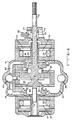
- the valve actuator is illustrated sequentially in Figures 1-8 to illustrate various component locations and functions in moving a poppet valve or other component (not shown) from a closed to an open position. Motion in s the opposite direction will be clearly understood from the symmetry of the components.
- the actuator includes a shaft or stem 11 which may form a part of or connect to an internal combustion engine poppet valve.
- the actuator also includes a low mass reciprocable piston 13, and a pair of reciprocating or sliding control valve members 15 and 17 enclosed within a housing 19.
- the control valve members 15 and 17 are latched in one position by permanent magnets 21 and 23 and may be dislodged from their respective latched positions by energization of coils 25 and 27.
- the permanent magnet latching arrangement also includes iron pole pieces 20 and 22.
- the control valve members or shuttle valves 15 and 17 cooperate with both the piston 13 and the housing 19 to achieve the various porting functions during operation.
- the housing 19 has a high pressure inlet port 39, a low pressure outlet port 41 and an intermediate pressure port 43.
- the low pressure may be about atmospheric pressure while the intermediate pressure is about 10 psi. above atmospheric pressure and the high pressure is on the order of 100 psi. gauge pressure.
- Figure 1 shows an initial state with piston 13 in the extreme leftward position and with the air control valve 15 latched closed.
- the annular abutment end surface 29 is inserted into an annular slot in the housing 19 and seals against an o-ring 31. This seals the pressure in cavity 33 and prevents the application of any moving force to the main piston 13.
- the main piston 13 is being urged to the left (latched) by the pressure in cavity or chamber 35 which is greater than the pressure in chamber or cavity 37.
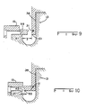
- annular opening 45 is in its final open position after having rapidly released compressed air from cavity 37 at the end of a previous leftward piston stroke. This rapid release is discussed in greater detail later in conjunction with Figures 9 and 10.
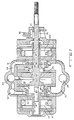
- the shuttle valve 15 has moved toward the left, for example, 0.05 in. while piston 13 has moved toward the right perhaps half that distance and air at a high pressure now enters the annular cavity 37 from cavity 33 applying a motive force to the left face 38 of piston 13.
- the air valve 15 has opened because of an electrical pulse applied to coil 25 which has temporarily neutralized the holding force on iron armature or plate 47 by permanent magnet 21.
- air pressure in cavity 33 which is applied to the air pressure responsive annular face 49 of valve 15 causes the valve to open.
- the communication between cavity 51 and the low pressure output port 41 has been interrupted by movement of the valve 15 before the valve clears the slot containing o-ring 31. This assures that no high pressure air escapes to the outlet port.
- the edge of air valve 15 has overlapped the piston 13 at 53 closing annular opening 45 of Figure 1 to assure rapid pressurization and maximum acceleration of the piston 13.
- Figure 3 shows the opening of the air valve 15 to about 0.10 in. (2/3 of its total travel) and movement of the piston 13 about 0.15 in. to the right.
- the high pressure air had been supplied to the cavity 37 and to the face 38 of piston 13 driving that piston toward the right. That high pressure air supply to cavity 37 is now cut off by the edge of piston 13 passing the annular abutment 55 of the housing 19.
- Piston 13 continues to accelerate, however, due to the expansion energy of the high pressure air in cavity 37.
- the right edge of piston 13 is about to cut off communication at 57 between the port 43 and chamber 35.
- Disk 47 is nearing the leftward extreme of its travel and is compressing air in the gap 61.
- the annular surface 62 which is shown as a portion of a right circular cylinder may be undercut (concave) or tapered (a conical surface) to restrict air flow more near one or both extremes of the travel of plate 47 to enhance damping without restricting motion intermediate the ends.
- a wave washer or other spring may be located between the disk 47 and the end of housing 19 to both add to the damping provided by the air trapped in the end chamber 61 ( Figure 3) and to give a more rapid return of the air valve to the closed position if desired.
- the main piston 13 has just closed off communication between chamber 35 and medium pressure port 43 and further rightward motion of the main piston will compress the air trapped in chamber 35 so that the piston will be slowed and stopped by the time it has reached its extreme right hand position.
- the air valve 15 is still in its extreme leftward position, but is just beginning to move toward the right to close the high pressure air port.
- the main piston has cleared the edge of the valve 15 and high pressure air from source 39 is now applying a force against surface 65.
- This additional force on the piston 13 will continue so long as the valve remains open.
- the air valve is designed to close at about the same time as the main piston arrives at its furthest right hand location so the piston will experience this additional force during the remainder of its rightward movement.
- Figure 9 illustrates the components in the same relative positions as in Figure 2 while Figure 10 depicts the components in the relative locations of Figure 1.
- blow-down or dumping of damping air from the piston has taken place through annular opening 45 between the piston valve edge 97 and the extended porting edge 99.
- high pressure air is being supplied through the opening between the air valve 15 and the fixed porting edge 101 to the face 38 of piston 13 to drive the piston toward the right.
- the distance y in Figure 9 which corresponds to the distance moved by the piston while air is being supplied to the face 38 is significantly greater than the distance x in Figure 10 which is the piston travel during blow-down. This difference is achieved by moving or translating the effective porting edge back and forth during actuator operation.
- the air valve 15 provides an extension at 99 of the fixed porting edge 101 when the air control valve is closed. This extension reduces the space (x in Figure 10) between the piston valve edge 97 and the porting edge (now 99) so that the damping blow-down occurs during a very short time period from the narrow slot 45. However, when the air valve 15 is open, this extension is rendered inoperative allowing a larger closing distance (y in Figure 9) between the piston valve edge 97 and the fixed porting edge 101 to assure a long power stroke.
- the distance (and therefore also the time) the piston travels while the port is open is considerably less than the length (and time) of piston travel toward the right while the port is open ( Figure 9).
- the damping of the piston motion near its right extremity is adjustable by controlling the intermediate pressure level at port 43 to effectively control the density of the air initially entrapped in chamber 35. If this intermediate pressure is too high, the piston will rebound due to the high pressure of the compressed air in chamber 35. If this pressure is too low, the piston will approach its end position too fast and may mechanically rebound due to metallic deflection or mechanical spring back. With the correct pressure, the piston will gently come to rest in its right hand position.
- a further final damping of piston motion may be provided during the last few thousandths of an inch of travel by a small hydraulic damper including a fluid medium filled cavity 73 and a small piston 75 fastened to and moving with the main piston 13.
- the small piston 75 enters a shallow annular restricted area 77 displacing the fluid therefrom and bringing the main piston to rest.
- Fluid such as oil, may be supplied to the damping cavity 73 by way of inlet 85.
- valve 15 is nearly completely closed to shut off the high pressure air supply to chamber 63, the high pressure air continues to exert a force on face 65 of piston 13 which will tend to stabilize the damping of piston motion which is occurring in chamber 35.
- the pressure in chamber 35 is being relieved through the annular opening 79 and through the opening 81 and channel 83 to the low pressure port 41 so that the pressure throughout chambers 35 and 86 is reduced to nearly atmospheric pressure.
- valves 15 and 17 include a number of apertures such as 93 and 95 in their respective web portions allowing free air flow between chambers 81 and 91 or 51 and 63.
- the piston 13 is reaching a very low velocity, the damping is almost complete and the final damping by the small fluid piston 75 is underway.
- the main piston 13 has reached its righthand extreme in Figure 8 and air valve 15 has closed off the supply of high pressure air from the source 39 to chamber 63.
- the respective annular openings 87 and 89 are venting chambers 63 and 35 to the low pressure port 41 and the piston is held or latched in the position shown by the intermediate pressure in chamber 37 from source 43.
Landscapes
- Engineering & Computer Science (AREA)
- Mechanical Engineering (AREA)
- General Engineering & Computer Science (AREA)
- Chemical & Material Sciences (AREA)
- Combustion & Propulsion (AREA)
- Valve Device For Special Equipments (AREA)
- Magnetically Actuated Valves (AREA)
- Fluid-Pressure Circuits (AREA)
Applications Claiming Priority (2)
| Application Number | Priority Date | Filing Date | Title |
|---|---|---|---|
| US153155 | 1988-02-08 | ||
| US07/153,155 US4899700A (en) | 1988-02-08 | 1988-02-08 | Pneumatically powered valve actuator |
Publications (1)
| Publication Number | Publication Date |
|---|---|
| EP0328193A1 true EP0328193A1 (de) | 1989-08-16 |
Family
ID=22545996
Family Applications (1)
| Application Number | Title | Priority Date | Filing Date |
|---|---|---|---|
| EP19890200225 Withdrawn EP0328193A1 (de) | 1988-02-08 | 1989-02-02 | Pneumatische Ventilbetätigungsvorrichtung |
Country Status (5)
| Country | Link |
|---|---|
| US (1) | US4899700A (de) |
| EP (1) | EP0328193A1 (de) |
| JP (1) | JPH01227806A (de) |
| KR (1) | KR890013389A (de) |
| CA (1) | CA1314773C (de) |
Cited By (4)
| Publication number | Priority date | Publication date | Assignee | Title |
|---|---|---|---|---|
| EP0377244A1 (de) * | 1989-01-06 | 1990-07-11 | Magnavox Electronic Systems Company | Schnell arbeitendes Ventil |
| EP0377251A1 (de) * | 1989-01-06 | 1990-07-11 | Magnavox Electronic Systems Company | Kompaktes Ventilstellglied |
| EP0438830A3 (en) * | 1989-12-26 | 1991-11-21 | Magnavox Government And Industrial Electronics Company | Improved pneumatically powered valve actuator |
| EP0548294B1 (de) * | 1991-07-12 | 1995-11-08 | Caterpillar Inc. | Verfahren zur betätigung einer hubventilvorrichtung mit rückgewinnung |
Families Citing this family (9)
| Publication number | Priority date | Publication date | Assignee | Title |
|---|---|---|---|---|
| ATE140515T1 (de) * | 1989-08-28 | 1996-08-15 | Nigel Eric Rose | Hydraulisches stellglied |
| US5022359A (en) * | 1990-07-24 | 1991-06-11 | North American Philips Corporation | Actuator with energy recovery return |
| US5193495A (en) * | 1991-07-16 | 1993-03-16 | Southwest Research Institute | Internal combustion engine valve control device |
| US6308690B1 (en) | 1994-04-05 | 2001-10-30 | Sturman Industries, Inc. | Hydraulically controllable camless valve system adapted for an internal combustion engine |
| US5829396A (en) | 1996-07-16 | 1998-11-03 | Sturman Industries | Hydraulically controlled intake/exhaust valve |
| DE19725218C2 (de) * | 1997-06-15 | 2000-11-02 | Daimler Chrysler Ag | Vorrichtung zur Betätigung eines Gaswechselventiles für eine Brennkraftmaschine |
| US6092545A (en) * | 1998-09-10 | 2000-07-25 | Hamilton Sundstrand Corporation | Magnetic actuated valve |
| EP2662139A1 (de) | 2012-05-08 | 2013-11-13 | Roche Diagniostics GmbH | Ventil zur Ausgabe einer Flüssigkeit |
| CA2888540A1 (en) | 2013-01-14 | 2014-08-14 | Dayco Ip Holdings, Llc | Piston actuator controlling a valve and method for operating the same |
Citations (3)
| Publication number | Priority date | Publication date | Assignee | Title |
|---|---|---|---|---|
| DE421002C (de) * | 1925-11-04 | D Aviat Louis Breguet Sa Des A | Steuerung von Ventilen, insbesondere fuer Explosionsmotoren, durch Fluessigkeiten oder Gase | |
| FR2133288A5 (de) * | 1971-04-15 | 1972-11-24 | Penhoet Loire Atlan Chan | |
| US3844528A (en) * | 1971-12-30 | 1974-10-29 | P Massie | Electrically operated hydraulic valve particularly adapted for pollution-free electronically controlled internal combustion engine |
Family Cites Families (5)
| Publication number | Priority date | Publication date | Assignee | Title |
|---|---|---|---|---|
| DE197808C (de) * | ||||
| US2552960A (en) * | 1946-09-27 | 1951-05-15 | Nordberg Manufacturing Co | Gas actuated inlet valve |
| CH592835A5 (de) * | 1975-04-29 | 1977-11-15 | Lucifer Sa | |
| CH620748A5 (de) * | 1978-04-04 | 1980-12-15 | Lucifer Sa | |
| US4605197A (en) * | 1985-01-18 | 1986-08-12 | Fema Corporation | Proportional and latching pressure control device |
-
1988
- 1988-02-08 US US07/153,155 patent/US4899700A/en not_active Expired - Lifetime
-
1989
- 1989-01-30 CA CA 589491 patent/CA1314773C/en not_active Expired - Fee Related
- 1989-02-02 EP EP19890200225 patent/EP0328193A1/de not_active Withdrawn
- 1989-02-04 KR KR1019890001313A patent/KR890013389A/ko not_active Abandoned
- 1989-02-06 JP JP1025938A patent/JPH01227806A/ja active Pending
Patent Citations (3)
| Publication number | Priority date | Publication date | Assignee | Title |
|---|---|---|---|---|
| DE421002C (de) * | 1925-11-04 | D Aviat Louis Breguet Sa Des A | Steuerung von Ventilen, insbesondere fuer Explosionsmotoren, durch Fluessigkeiten oder Gase | |
| FR2133288A5 (de) * | 1971-04-15 | 1972-11-24 | Penhoet Loire Atlan Chan | |
| US3844528A (en) * | 1971-12-30 | 1974-10-29 | P Massie | Electrically operated hydraulic valve particularly adapted for pollution-free electronically controlled internal combustion engine |
Cited By (4)
| Publication number | Priority date | Publication date | Assignee | Title |
|---|---|---|---|---|
| EP0377244A1 (de) * | 1989-01-06 | 1990-07-11 | Magnavox Electronic Systems Company | Schnell arbeitendes Ventil |
| EP0377251A1 (de) * | 1989-01-06 | 1990-07-11 | Magnavox Electronic Systems Company | Kompaktes Ventilstellglied |
| EP0438830A3 (en) * | 1989-12-26 | 1991-11-21 | Magnavox Government And Industrial Electronics Company | Improved pneumatically powered valve actuator |
| EP0548294B1 (de) * | 1991-07-12 | 1995-11-08 | Caterpillar Inc. | Verfahren zur betätigung einer hubventilvorrichtung mit rückgewinnung |
Also Published As
| Publication number | Publication date |
|---|---|
| KR890013389A (ko) | 1989-09-22 |
| CA1314773C (en) | 1993-03-23 |
| JPH01227806A (ja) | 1989-09-12 |
| US4899700A (en) | 1990-02-13 |
Similar Documents
| Publication | Publication Date | Title |
|---|---|---|
| US4852528A (en) | Pneumatic actuator with permanent magnet control valve latching | |
| US4831973A (en) | Repulsion actuated potential energy driven valve mechanism | |
| EP0328194B1 (de) | Ventilvorrichtung mit potentiellem magnetischen Antrieb | |
| US4899700A (en) | Pneumatically powered valve actuator | |
| US5058538A (en) | Hydraulically propelled phneumatically returned valve actuator | |
| US4873948A (en) | Pneumatic actuator with solenoid operated control valves | |
| US4967702A (en) | Fast acting valve | |
| US4915015A (en) | Pneumatic actuator | |
| US4942852A (en) | Electro-pneumatic actuator | |
| US5022359A (en) | Actuator with energy recovery return | |
| US4991548A (en) | Compact valve actuator | |
| US4875441A (en) | Enhanced efficiency valve actuator | |
| US4872425A (en) | Air powered valve actuator |
Legal Events
| Date | Code | Title | Description |
|---|---|---|---|
| PUAI | Public reference made under article 153(3) epc to a published international application that has entered the european phase |
Free format text: ORIGINAL CODE: 0009012 |
|
| AK | Designated contracting states |
Kind code of ref document: A1 Designated state(s): DE ES FR GB IT SE |
|
| 17P | Request for examination filed |
Effective date: 19900214 |
|
| 17Q | First examination report despatched |
Effective date: 19911010 |
|
| RAP1 | Party data changed (applicant data changed or rights of an application transferred) |
Owner name: MAGNAVOX ELECTRONIC SYSTEMS COMPANY |
|
| STAA | Information on the status of an ep patent application or granted ep patent |
Free format text: STATUS: THE APPLICATION HAS BEEN WITHDRAWN |
|
| 18W | Application withdrawn |
Withdrawal date: 19940228 |