EP0328221A1 - Dispositif pour transporter une personne handicapée - Google Patents
Dispositif pour transporter une personne handicapée Download PDFInfo
- Publication number
- EP0328221A1 EP0328221A1 EP89200295A EP89200295A EP0328221A1 EP 0328221 A1 EP0328221 A1 EP 0328221A1 EP 89200295 A EP89200295 A EP 89200295A EP 89200295 A EP89200295 A EP 89200295A EP 0328221 A1 EP0328221 A1 EP 0328221A1
- Authority
- EP
- European Patent Office
- Prior art keywords
- seat
- slide portion
- backrest
- movable
- carriage
- Prior art date
- Legal status (The legal status is an assumption and is not a legal conclusion. Google has not performed a legal analysis and makes no representation as to the accuracy of the status listed.)
- Withdrawn
Links
- 238000010276 construction Methods 0.000 claims description 6
- 230000007935 neutral effect Effects 0.000 claims description 3
- 230000005484 gravity Effects 0.000 description 4
- 238000005452 bending Methods 0.000 description 1
- 230000002349 favourable effect Effects 0.000 description 1
- 238000012986 modification Methods 0.000 description 1
- 230000004048 modification Effects 0.000 description 1
- 230000000474 nursing effect Effects 0.000 description 1
Images

Classifications
-
- A—HUMAN NECESSITIES
- A61—MEDICAL OR VETERINARY SCIENCE; HYGIENE
- A61G—TRANSPORT, PERSONAL CONVEYANCES, OR ACCOMMODATION SPECIALLY ADAPTED FOR PATIENTS OR DISABLED PERSONS; OPERATING TABLES OR CHAIRS; CHAIRS FOR DENTISTRY; FUNERAL DEVICES
- A61G7/00—Beds specially adapted for nursing; Devices for lifting patients or disabled persons
- A61G7/10—Devices for lifting patients or disabled persons, e.g. special adaptations of hoists thereto
- A61G7/1013—Lifting of patients by
- A61G7/1019—Vertical extending columns or mechanisms
-
- A—HUMAN NECESSITIES
- A61—MEDICAL OR VETERINARY SCIENCE; HYGIENE
- A61G—TRANSPORT, PERSONAL CONVEYANCES, OR ACCOMMODATION SPECIALLY ADAPTED FOR PATIENTS OR DISABLED PERSONS; OPERATING TABLES OR CHAIRS; CHAIRS FOR DENTISTRY; FUNERAL DEVICES
- A61G5/00—Chairs or personal conveyances specially adapted for patients or disabled persons, e.g. wheelchairs
- A61G5/006—Chairs or personal conveyances specially adapted for patients or disabled persons, e.g. wheelchairs convertible to stretchers or beds
-
- A—HUMAN NECESSITIES
- A61—MEDICAL OR VETERINARY SCIENCE; HYGIENE
- A61G—TRANSPORT, PERSONAL CONVEYANCES, OR ACCOMMODATION SPECIALLY ADAPTED FOR PATIENTS OR DISABLED PERSONS; OPERATING TABLES OR CHAIRS; CHAIRS FOR DENTISTRY; FUNERAL DEVICES
- A61G5/00—Chairs or personal conveyances specially adapted for patients or disabled persons, e.g. wheelchairs
- A61G5/10—Parts, details or accessories
- A61G5/1056—Arrangements for adjusting the seat
- A61G5/1059—Arrangements for adjusting the seat adjusting the height of the seat
-
- A—HUMAN NECESSITIES
- A61—MEDICAL OR VETERINARY SCIENCE; HYGIENE
- A61G—TRANSPORT, PERSONAL CONVEYANCES, OR ACCOMMODATION SPECIALLY ADAPTED FOR PATIENTS OR DISABLED PERSONS; OPERATING TABLES OR CHAIRS; CHAIRS FOR DENTISTRY; FUNERAL DEVICES
- A61G7/00—Beds specially adapted for nursing; Devices for lifting patients or disabled persons
- A61G7/05—Parts, details or accessories of beds
- A61G7/0528—Steering or braking devices for castor wheels
-
- A—HUMAN NECESSITIES
- A61—MEDICAL OR VETERINARY SCIENCE; HYGIENE
- A61G—TRANSPORT, PERSONAL CONVEYANCES, OR ACCOMMODATION SPECIALLY ADAPTED FOR PATIENTS OR DISABLED PERSONS; OPERATING TABLES OR CHAIRS; CHAIRS FOR DENTISTRY; FUNERAL DEVICES
- A61G7/00—Beds specially adapted for nursing; Devices for lifting patients or disabled persons
- A61G7/10—Devices for lifting patients or disabled persons, e.g. special adaptations of hoists thereto
- A61G7/1025—Lateral movement of patients, e.g. horizontal transfer
- A61G7/1032—Endless belts
-
- A—HUMAN NECESSITIES
- A61—MEDICAL OR VETERINARY SCIENCE; HYGIENE
- A61G—TRANSPORT, PERSONAL CONVEYANCES, OR ACCOMMODATION SPECIALLY ADAPTED FOR PATIENTS OR DISABLED PERSONS; OPERATING TABLES OR CHAIRS; CHAIRS FOR DENTISTRY; FUNERAL DEVICES
- A61G7/00—Beds specially adapted for nursing; Devices for lifting patients or disabled persons
- A61G7/10—Devices for lifting patients or disabled persons, e.g. special adaptations of hoists thereto
- A61G7/104—Devices carried or supported by
- A61G7/1046—Mobile bases, e.g. having wheels
-
- A—HUMAN NECESSITIES
- A61—MEDICAL OR VETERINARY SCIENCE; HYGIENE
- A61G—TRANSPORT, PERSONAL CONVEYANCES, OR ACCOMMODATION SPECIALLY ADAPTED FOR PATIENTS OR DISABLED PERSONS; OPERATING TABLES OR CHAIRS; CHAIRS FOR DENTISTRY; FUNERAL DEVICES
- A61G7/00—Beds specially adapted for nursing; Devices for lifting patients or disabled persons
- A61G7/10—Devices for lifting patients or disabled persons, e.g. special adaptations of hoists thereto
- A61G7/1049—Attachment, suspending or supporting means for patients
- A61G7/1057—Supported platforms, frames or sheets for patient in lying position
Definitions
- the invention relates to a device for moving an invalid person, said device comprising a carriage provided with a number of wheels, means being provided on said carriage to take up a frame which is adjustable in height for supporting a seat-lying place comprising a backrest, a seat and a seat element which can be brought sideways beside the seat and in one plane with this for bridging the distance between another seat-lying place and said seat.
- Such a device is known from EP-A-0 067 069.
- This known device is used such that the seat, together with the seat element extending from it can be brought simultaneously below a patient. After this, however, the patient has to be rotated over 90° around a vertical axis to be able to sit down in the chair. So such a device is only limited usable.
- the invention provides a device of the type described above which is characterized in that said seat element comprises a slide portion being movable in respect of the seat such that in the retracted position the slide portion and the seat will be substantially positioned one above the other, and a hinged portion being pivotally connected to that edge of the slide portion which in the extended position is at the greatest distance from the seat, which hinged portion can be pivoted to a vertical position, one endless conveyor belt which can be motor-driven, running over the in the position of use upwardly directed surfaces of the seat and of both portions of the seat element.
- NL-A-70 10301 by which it is known to use an endless conveyor belt for the transport of patients.
- a stretcher the upper surface of which is formed by a conveyor belt running in longitudinal direction of the stretcher so that a lying patient can be shifted in longitudinal direction onto the stretcher.
- the slide portion of the seat element is present below the seat in the retracted position, a tensioning roller being provided below the slide portion over which the conveyor belt extends over substantially 180°, said tensioning roller being rotatable around a shaft which is movable in a direction perpendicular to its center line to maintain the endless belt tensioned when the slide portion is slid below the seat and the conveyor belt is released from the upper surface of the slide portion.
- At least the support surface of the backrest is sideways slidable in its plane such that it can be brought at the position of the slide portion of the seat element which is slid outwardly.
- the backrest is pivotable around a hinged shaft running parallel to the rear edge of the seat, the backrest being adjustable till a position in which it is nearly lying in one plane with the seat, a leg support being hingedly connected near the front edge of the seat such that it can be brought into a position in which it is nearly lying in one plane with the seat, at least the support surface of the leg support being sidewards movable in its plane such that it can be brought at the position of the outwardly moved slide portion of the seat element.
- an elongated mainly flat surface can be obtained with a length being larger than the length of a patient.
- This surface can be brought onto or against e.g. a treatment table or bed, the hinged portion of the seat element connected to the slide portion extending outside said surface.
- the hinged portion By rotating the patient somewhat the hinged portion can be slid under him over a given distance after which he can be brought totally on the surface formed by seat, backrest and leg support by means of the conveyor belt.
- the backrest is provided with arm rests which are pivotally so that they substantially can come to lie in the plane of the backrest.
- the arm rest being positioned at the same side as the slide portion of the seat element will be positioned behind the support surface of the backrest and will not move outwardly with this support surface. Then the armrest cannot form an obstruction when transferring a patient from a seat-lying place onto the device according to the present invention or vice versa.
- the seat-lying place is slidable in longitudinal direction of a person lying on the device in respect of the frame and within certain limits.
- the backrest is pivotally connected to a rod in a point spaced from the hinge axis of it, the other end of said rod being pivotally connected with the frame in a point that, in the about vertical position of the backrest is positioned behind the backrest.
- a double expanding brace construction in which two free ends of the braces which are vertically lying above each other are pivotally connected to fixed places of the carriage and the frame respectively while the other free ends are movable in horizontal direction in respect of the carriage and the frame.
- the height adjustment of the frame will take place by means of a spindle-motor taking care for longitudinal movement of a mainly vertical running rod which by means of pivoting tension rods is connected to portions of the brace construction.
- all wheels of the carriage will be swivel wheels and means will be provided to brake said wheels from a central point and for locking at least one pair of swivel wheels in such a position that the rotating axes of said wheels will be aligned.
- the device By providing four swivel wheels the device can be easily brought in the right position near an other seat-lying place and can be fixed in this position because each wheel can be fixed by means of a brake member.
- a swivel wheel comprises a push rod which is movable in substantially vertical direction and the center line of which is aligned with the swivel axis of the swivel wheel, said push rod at its lower end being provided with a brake shoe and being movable downwardly from a neutral position to brake the wheel by means of the brake shoe and is movable upwardly to cooperate with an element connected to the fork of the swivel wheel to lock the fork in a given position.
- the push rod can be controlled by means of a cam the rotating axis of which is running transverse to the longitudinal direction of the push rod, said push rod being biased against the cam by means of a spring.
- the cams of two swivel wheels positioned at both sides of the carriage are present at a fixed place and can be connected to each other e.g. by means of one axis.
- This axis e.g. can be rotated by means of a foot pedal to bring the cam in the desired position.
- the two parallel running axes each carrying two cams can be coupled in such a way that when rotating the one axis to a position in which the wheels are braked the other axis is automatically rotated to the same position. When rotating the axis in opposite direction the other axis is not taken along.
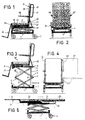
- the device which is particularly shown in the Figs. 1-5 comprises a carriage 1 provided with four swivel wheels 2.
- the carriage 1 supports an expanding brace construction 3 which at both sides of the carriage comprises a system 4 of braces 5.
- the braces 5 are connected to each other in the points 6.
- the one lowest brace 5 is pivotally connected with the carriage 1 in the point 7 while the other brace is provided with a roller 8 which in a not shown way is taken up in a profile of the carriage 1 in such a way that the roller 8 can only move in the direction of the arrow P, see Fig. 3.
- two upper braces 5 are pivotally connected to a frame 10 in the points 9, the ends of the other braces 5 being provided with a roller 11, see Fig. 6, which is taken up in a profile 12 of the frame 10.
- a spindle-motor 13 is provided, being mounted on the carriage 1 and taking care for moving a rod 14 in vertical direction.
- two strips 15 are pivotally connected, said strips running obliquely downwardly along the rod.
- the lower ends of both strips 15 are pivotally connected to two legs 16 being fixed to a hinge pin 17 extending between the two brace systems 4 as appears from Fig. 2.
- a seat-lying place 18 is supported in such a way that it is adjustable in the direction of the arrow P, see Fig. 1, in respect of the frame 10 and so in respect of the carriage 1.
- the seat-lying place 18 e.g. can comprise profiles 19 being slidable over rollers 20 connected to the frame 10.
- the seat-lying place comprises a backrest 21, a seat 22, a seat element 23 and a leg support 24.
- Fig. 1 shows the backrest and the leg support in a position in which the device is forming a wheel chair.
- Fig. 5 shows the backrest 21 and the leg support 24 in one plane with the seat 22 so that a patient can be transported in lying position. If necessary a head cushion can be mounted on the backrest 21.
- the backrest 21 is connected to the frame 10 by means of pivotable rods 26, the backrest being pivotally connected to the seat 22 in the point 27.
- the leg support 24 also is pivotally connected to the seat 22 in the point 28.
- control means will be provided which can be of a known type and need not be further discussed. It might be desirable that e.g. in case of a vertical position of the backrest 21 the leg support 24 is extending horizontally.
- the backrest 21 comprises a support surface 29 which is mounted shiftable as shown in Fig. 4, e.g. by means of the double guiding rail 30, shown in Fig. 1. So the further portion of the backrest remains at its place.
- leg support 24 can be provided with a support surface 31, which is sidewards movable to transfer a patient easier from one seat-lying place on another one.
- the support surface 31 then will come to lie in line with the support surface 29 which is shown in Fig. 4.
- the backrest 21 can be provided with rods 32 which can be used for driving the device in particular when this is used as wheel chair.
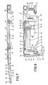
- Figs. 6 and 7 show in particular the seat element 23 which can be moved outwardly in respect of the seat 22 from the position shown in Fig. 6 to the position which is shown in Fig. 4 by means of dashed lines.
- the seat element comprises the slide portion 33 and a hinged portion 34, said portions being connected to each other in the hinge point 35.
- the slide portion 33 consists of the upper plate 36 and the lower plate 37 being connected to each other by means of some vertical plate portion 38.
- the slide portion 33 is shiftable supported by means of not shown rollers being connected to the seat 22 in such a way that the upper plate 36 of the slide portion 33 is lying against the lower side of the upper plate 39 of the seat 22.
- the hinged portion 34 consists of the upper plate 40 and the lower plate 41 being connected to each other by means of vertical plate portions 42.
- a screwed spindle 43 is present which by means of a thrust bearing 44 is rotatable but axially not movable supported by a part 45 fixedly connected to the seat 22.
- a gear wheel 46 is fixedly connected and over this gear wheel a geared belt 47 is running which in a not further shown way can be driven by means of the electric motor 48.
- the sleeve 49 On the screwed spindle 43 the sleeve 49 is present which is provided with inner screw thread, said sleeve being not rotatable in respect of the slide portion 33 and by means of a shoulder 50 is engaging an abutment 51 which is fixedly connected to the slide portion 33.
- a slide sleeve 52 is movable and this slide sleeve is connected to the hinged portion 34 by means of at least one rod 53, to wit in the hinge point 54 which is spaced apart from the hinge point 35 between the slide portion 33 and the hinge portion 34.
- the screwed spindle 53 can be rotated during which the sleeve 49 will be moved to the left, the slide portion 33 moving to the left by means of the shoulder 50 and the abutment 51. After a given movement of the sleeve 49 and so moving the slide portion 33 outwardly over a given distance the slide sleeve 52 is engaging the thrust bearing 55. When the spindle 43 is rotated further the shoulder 50 of the sleeve 49 is moving towards the slide sleeve 52 so that the hinge point 35 will move further to the left in respect of the hinge point 54 between the slide portion 33 and the hinged portion 34.
- a conveyor belt 57 is provided which may extend over the upper surface of the upper plate 39 of the seat 22, of the upper plate 36 of the slide portion 33 and of the upper plate 40 of the hinged portion 34. This is the case in the position of the parts as shown in Fig. 7.
- the conveyor belt further is running over two reversing rolls 58, at least one of these may be driven from the motor 59 by means not further indicated.
- the conveyor belt 57 is running over the guiding rolls 60 positioned at a fixed place in respect of the seat 22, over a movable reversing roll 61, over guiding rolls 62 in the hinged portion 24, a reserving roll 63 near the end of the hinged portion 34 and along a further guiding roll 64, if any, which is only working when the hinged portion is in its horizontal position shown in Fig. 7.
- the reversing roll 61 is rotatable around a shaft 65 which near its ends is supported by means of not further indicated slide blocks being movably comprised in slots 66, provided in two vertical plate sections 67 forming part of the seat 22.
- each swivel wheel 2 comprises a wheel 69 which by means of a shaft 70 is rotatably supported in the fork 71.
- the fork comprises an upper plate 72 and a sleeve 73 extending from this, said sleeve being rotatable but axially not movable received in a sleeve 74 which can be fixedly connected to the carriage 1 of the device.
- the support plate 75 also can be connected to the carriage 1 against which the upper plate 72 is lying e.g. by means of a not shown thrust bearing.
- the push rod 76 is extending through the sleeve 73 and is movably guided in vertical direction and is provided at its lower end with the brake shoe 77. Near its upper end the push rod 76 is provided with the abutment surface 78, which by means of a not shown spring is biased against a cam 79 mounted on a shaft 80, which e.g. extends between the two cams 79 present at both sides of the carriage 1.
- the cam 79 can be brought into three positions.
- a first position is shown in Fig. 8. In case of this the push rod 76 is present in the middle position and the brake shoe 77 is free of the wheel 69.
- the cam 79 is moved to the position shown in Fig. 9. In case of this the push rod 76 is pressed downwardly and the brake shoe 77 is engaging the wheel 69.
- the shaft 80 also can be rotated in opposite direction so that then the push rod 76 is engaging a portion of the cam 79 with a smaller diameter, so that the push rod 76 is pressed upwardly.
- a pawl 81 connected to the fork 71 can be received in a slot 82 provided in a part 83 being connected to the carriage 1. So then the fork 71 is locked against rotating so that the swivel wheels 2 principally are now fixed wheels.
- the two ends of the shaft 80 each can be connected to a pawl 81 so that when rotating the shaft 80, e.g. by means of a foot pedal, both cams 79 simultaneously will be rotated to a given position.
- the shaft 80 will extend transverse to the normal direction of driving of the device and so transverse to the plane in which the device is projected in the Figs. 1, 3 and 5.
- the shaft 80 present near the most left pair of wheels as shown in Fig. 1, might be controlled by a foot pedal by means of a rod, said foot pedal being provided near the shaft 80 present near the most right pair of wheels. Then the controlling of the two shafts 80 can take place from a central point.
- the controlling of the shaft 80 also can be done by means of a motor in a not further shown way.
- a motor for controlling these motors, if any, and of the motors 13, 48 and 59 use can be made of a single control panel which is connected to the carriage by means of a cable so that the controlling of the various motors can take place from a single, variable place near the device.
Landscapes
- Health & Medical Sciences (AREA)
- Life Sciences & Earth Sciences (AREA)
- Animal Behavior & Ethology (AREA)
- General Health & Medical Sciences (AREA)
- Public Health (AREA)
- Veterinary Medicine (AREA)
- Nursing (AREA)
- Accommodation For Nursing Or Treatment Tables (AREA)
- Invalid Beds And Related Equipment (AREA)
Applications Claiming Priority (2)
| Application Number | Priority Date | Filing Date | Title |
|---|---|---|---|
| NL8800326 | 1988-02-10 | ||
| NL8800326A NL8800326A (nl) | 1988-02-10 | 1988-02-10 | Inrichting voor het verplaatsen van een invalide persoon. |
Publications (1)
| Publication Number | Publication Date |
|---|---|
| EP0328221A1 true EP0328221A1 (fr) | 1989-08-16 |
Family
ID=19851750
Family Applications (1)
| Application Number | Title | Priority Date | Filing Date |
|---|---|---|---|
| EP89200295A Withdrawn EP0328221A1 (fr) | 1988-02-10 | 1989-02-09 | Dispositif pour transporter une personne handicapée |
Country Status (2)
| Country | Link |
|---|---|
| EP (1) | EP0328221A1 (fr) |
| NL (1) | NL8800326A (fr) |
Cited By (7)
| Publication number | Priority date | Publication date | Assignee | Title |
|---|---|---|---|---|
| EP0734706A1 (fr) * | 1995-03-28 | 1996-10-02 | Fredi Luderich GmbH | Chaise pour malades et handicapés |
| US5613697A (en) * | 1994-11-18 | 1997-03-25 | Johnson; David D. | Elevatable wheelchair |
| EP1106155A3 (fr) * | 1999-12-06 | 2002-05-22 | Yves Birbaum | Fauteuil roulant manuel |
| US6540250B1 (en) * | 2000-05-12 | 2003-04-01 | Clifford D. Peterson | Height adjustable wheelchair |
| GB2436930A (en) * | 2006-02-09 | 2007-10-10 | Roy Targonski | Elevation chair |
| GB2509049A (en) * | 2012-11-05 | 2014-06-25 | James Spencer & Co Ltd | A chair with a pivoting armrest to improve access |
| WO2022216206A1 (fr) * | 2021-04-07 | 2022-10-13 | Arjo IP Holding Aktiebolag | Ensemble de freinage d'un moyen de transport pour un appareil de manipulation de patient |
Citations (10)
| Publication number | Priority date | Publication date | Assignee | Title |
|---|---|---|---|---|
| US2146191A (en) * | 1937-03-16 | 1939-02-07 | Henry E Peters | Flexible health chair |
| GB523114A (en) * | 1938-12-23 | 1940-07-05 | Robert Mawby | Improvements in or relating to wheeled stretchers, hand trollies and like hand-propelled carriages |
| US2982336A (en) * | 1959-02-13 | 1961-05-02 | Joe P Minici | Portable and adjustable wheel chair |
| US3057638A (en) * | 1960-05-19 | 1962-10-09 | Margit H Floyd | Ambulatory seating device |
| NL7010301A (fr) * | 1970-03-02 | 1971-09-06 | ||
| US3967328A (en) * | 1974-09-06 | 1976-07-06 | Cox Ellis V | Load lifting and transferring device with multiple powered belts |
| US4101143A (en) * | 1977-01-03 | 1978-07-18 | American Safety Equipment Corporation | Wheelchairs |
| US4155588A (en) * | 1976-05-03 | 1979-05-22 | Reuven Danziger | Wheelchair |
| EP0067069A1 (fr) * | 1981-06-10 | 1982-12-15 | Harold Swallow | Fauteuils pour invalides |
| WO1987001583A1 (fr) * | 1984-04-10 | 1987-03-26 | Svein Bekkelund | Agencement de chaise roulante |
-
1988
- 1988-02-10 NL NL8800326A patent/NL8800326A/nl not_active Application Discontinuation
-
1989
- 1989-02-09 EP EP89200295A patent/EP0328221A1/fr not_active Withdrawn
Patent Citations (10)
| Publication number | Priority date | Publication date | Assignee | Title |
|---|---|---|---|---|
| US2146191A (en) * | 1937-03-16 | 1939-02-07 | Henry E Peters | Flexible health chair |
| GB523114A (en) * | 1938-12-23 | 1940-07-05 | Robert Mawby | Improvements in or relating to wheeled stretchers, hand trollies and like hand-propelled carriages |
| US2982336A (en) * | 1959-02-13 | 1961-05-02 | Joe P Minici | Portable and adjustable wheel chair |
| US3057638A (en) * | 1960-05-19 | 1962-10-09 | Margit H Floyd | Ambulatory seating device |
| NL7010301A (fr) * | 1970-03-02 | 1971-09-06 | ||
| US3967328A (en) * | 1974-09-06 | 1976-07-06 | Cox Ellis V | Load lifting and transferring device with multiple powered belts |
| US4155588A (en) * | 1976-05-03 | 1979-05-22 | Reuven Danziger | Wheelchair |
| US4101143A (en) * | 1977-01-03 | 1978-07-18 | American Safety Equipment Corporation | Wheelchairs |
| EP0067069A1 (fr) * | 1981-06-10 | 1982-12-15 | Harold Swallow | Fauteuils pour invalides |
| WO1987001583A1 (fr) * | 1984-04-10 | 1987-03-26 | Svein Bekkelund | Agencement de chaise roulante |
Cited By (7)
| Publication number | Priority date | Publication date | Assignee | Title |
|---|---|---|---|---|
| US5613697A (en) * | 1994-11-18 | 1997-03-25 | Johnson; David D. | Elevatable wheelchair |
| EP0734706A1 (fr) * | 1995-03-28 | 1996-10-02 | Fredi Luderich GmbH | Chaise pour malades et handicapés |
| EP1106155A3 (fr) * | 1999-12-06 | 2002-05-22 | Yves Birbaum | Fauteuil roulant manuel |
| US6540250B1 (en) * | 2000-05-12 | 2003-04-01 | Clifford D. Peterson | Height adjustable wheelchair |
| GB2436930A (en) * | 2006-02-09 | 2007-10-10 | Roy Targonski | Elevation chair |
| GB2509049A (en) * | 2012-11-05 | 2014-06-25 | James Spencer & Co Ltd | A chair with a pivoting armrest to improve access |
| WO2022216206A1 (fr) * | 2021-04-07 | 2022-10-13 | Arjo IP Holding Aktiebolag | Ensemble de freinage d'un moyen de transport pour un appareil de manipulation de patient |
Also Published As
| Publication number | Publication date |
|---|---|
| NL8800326A (nl) | 1989-09-01 |
Similar Documents
| Publication | Publication Date | Title |
|---|---|---|
| US2587068A (en) | Invalid lift and transfer apparatus | |
| DE69019450T2 (de) | Rollstuhl für jeden Zweck. | |
| US6382725B1 (en) | Examination chair with lifting and tilting mechanism | |
| US6427263B1 (en) | Device for moving patients | |
| US4987622A (en) | Self-operated stand up support apparatus | |
| US4119164A (en) | Stand-aid invalid wheelchair | |
| US4527829A (en) | Foldable wheel chair, especially for invalids | |
| US5044647A (en) | Stabilized reclining wheelchair seat | |
| US6540250B1 (en) | Height adjustable wheelchair | |
| US3379450A (en) | Adjustable wheelchair device | |
| US5520403A (en) | Wheelchair with translating seat and patient lift | |
| US5916085A (en) | Rotator for assisting a person in lying down on and getting up from a bed and method of use | |
| US6454285B1 (en) | Ergonomic wheelchair with patient lifting mechanism | |
| US5346280A (en) | Chair with automatic standing aid | |
| US3261031A (en) | Patient handler | |
| FI77570C (fi) | Foerfarande och anordning foer att utan tunga lyft foera en roerelsehaemmad person fraon sittande till liggande staellning. | |
| EP1165005B1 (fr) | Système de transport de patient | |
| US3010121A (en) | Adjustable support device | |
| US5385154A (en) | Couple's intimacy reciprocating and pivoting two seat assembly | |
| US20060000021A1 (en) | Profiling bed | |
| US5179745A (en) | Elevating convertible wheelchair | |
| US5007118A (en) | Head care station and kit and method for reclining the occupant of a wheelchair against a head support | |
| US5596775A (en) | Patient transfer seat | |
| EP0328221A1 (fr) | Dispositif pour transporter une personne handicapée | |
| US3404679A (en) | Medical therapy table |
Legal Events
| Date | Code | Title | Description |
|---|---|---|---|
| PUAI | Public reference made under article 153(3) epc to a published international application that has entered the european phase |
Free format text: ORIGINAL CODE: 0009012 |
|
| AK | Designated contracting states |
Kind code of ref document: A1 Designated state(s): AT BE CH DE ES FR GB GR IT LI LU NL SE |
|
| STAA | Information on the status of an ep patent application or granted ep patent |
Free format text: STATUS: THE APPLICATION IS DEEMED TO BE WITHDRAWN |
|
| 18D | Application deemed to be withdrawn |
Effective date: 19900219 |