EP0328334B1 - Verfahren und Vorrichtung zur Überwachung des Trübungspunktes oder eines ähnlichen thermischen Überganges - Google Patents
Verfahren und Vorrichtung zur Überwachung des Trübungspunktes oder eines ähnlichen thermischen Überganges Download PDFInfo
- Publication number
- EP0328334B1 EP0328334B1 EP89301141A EP89301141A EP0328334B1 EP 0328334 B1 EP0328334 B1 EP 0328334B1 EP 89301141 A EP89301141 A EP 89301141A EP 89301141 A EP89301141 A EP 89301141A EP 0328334 B1 EP0328334 B1 EP 0328334B1
- Authority
- EP
- European Patent Office
- Prior art keywords
- light
- sample
- temperature
- receptacle
- scattered
- Prior art date
- Legal status (The legal status is an assumption and is not a legal conclusion. Google has not performed a legal analysis and makes no representation as to the accuracy of the status listed.)
- Expired - Lifetime
Links
- 238000000034 method Methods 0.000 title claims description 19
- 230000007704 transition Effects 0.000 title claims description 9
- 238000012544 monitoring process Methods 0.000 title claims description 7
- 239000007788 liquid Substances 0.000 claims description 33
- 238000000149 argon plasma sintering Methods 0.000 claims description 20
- 239000012071 phase Substances 0.000 claims description 15
- 238000005259 measurement Methods 0.000 claims description 13
- 238000001514 detection method Methods 0.000 claims description 10
- 239000007791 liquid phase Substances 0.000 claims description 9
- 239000000463 material Substances 0.000 claims description 9
- 238000012360 testing method Methods 0.000 claims description 6
- 230000001154 acute effect Effects 0.000 claims description 4
- 230000008859 change Effects 0.000 claims description 4
- 238000004140 cleaning Methods 0.000 claims description 4
- 239000004020 conductor Substances 0.000 claims description 4
- 238000009529 body temperature measurement Methods 0.000 claims description 3
- 239000012141 concentrate Substances 0.000 claims description 3
- 238000001035 drying Methods 0.000 claims description 2
- 238000002834 transmittance Methods 0.000 claims description 2
- 239000002184 metal Substances 0.000 claims 1
- 238000012545 processing Methods 0.000 claims 1
- 238000001816 cooling Methods 0.000 description 17
- 239000007787 solid Substances 0.000 description 10
- XLYOFNOQVPJJNP-UHFFFAOYSA-N water Chemical compound O XLYOFNOQVPJJNP-UHFFFAOYSA-N 0.000 description 9
- 239000007789 gas Substances 0.000 description 8
- 238000002844 melting Methods 0.000 description 7
- 230000008018 melting Effects 0.000 description 7
- UHOVQNZJYSORNB-UHFFFAOYSA-N Benzene Chemical compound C1=CC=CC=C1 UHOVQNZJYSORNB-UHFFFAOYSA-N 0.000 description 6
- ZMANZCXQSJIPKH-UHFFFAOYSA-N Triethylamine Chemical compound CCN(CC)CC ZMANZCXQSJIPKH-UHFFFAOYSA-N 0.000 description 6
- 238000002474 experimental method Methods 0.000 description 6
- 238000007710 freezing Methods 0.000 description 6
- 230000008014 freezing Effects 0.000 description 6
- 239000003921 oil Substances 0.000 description 6
- IJDNQMDRQITEOD-UHFFFAOYSA-N n-butane Chemical compound CCCC IJDNQMDRQITEOD-UHFFFAOYSA-N 0.000 description 5
- FAPWRFPIFSIZLT-UHFFFAOYSA-M Sodium chloride Chemical compound [Na+].[Cl-] FAPWRFPIFSIZLT-UHFFFAOYSA-M 0.000 description 4
- 230000015572 biosynthetic process Effects 0.000 description 4
- 239000013078 crystal Substances 0.000 description 4
- XDTMQSROBMDMFD-UHFFFAOYSA-N Cyclohexane Chemical compound C1CCCCC1 XDTMQSROBMDMFD-UHFFFAOYSA-N 0.000 description 3
- 238000009835 boiling Methods 0.000 description 3
- 230000000694 effects Effects 0.000 description 3
- 239000000203 mixture Substances 0.000 description 3
- 239000003208 petroleum Substances 0.000 description 3
- 238000007711 solidification Methods 0.000 description 3
- 230000008023 solidification Effects 0.000 description 3
- 238000004458 analytical method Methods 0.000 description 2
- 230000007423 decrease Effects 0.000 description 2
- 239000002283 diesel fuel Substances 0.000 description 2
- 239000012153 distilled water Substances 0.000 description 2
- BASFCYQUMIYNBI-UHFFFAOYSA-N platinum Chemical compound [Pt] BASFCYQUMIYNBI-UHFFFAOYSA-N 0.000 description 2
- 239000011780 sodium chloride Substances 0.000 description 2
- 238000004781 supercooling Methods 0.000 description 2
- RYGMFSIKBFXOCR-UHFFFAOYSA-N Copper Chemical compound [Cu] RYGMFSIKBFXOCR-UHFFFAOYSA-N 0.000 description 1
- 241000220317 Rosa Species 0.000 description 1
- 230000002528 anti-freeze Effects 0.000 description 1
- 238000009833 condensation Methods 0.000 description 1
- 230000005494 condensation Effects 0.000 description 1
- 229910052802 copper Inorganic materials 0.000 description 1
- 239000010949 copper Substances 0.000 description 1
- 238000012864 cross contamination Methods 0.000 description 1
- 238000010586 diagram Methods 0.000 description 1
- 238000007599 discharging Methods 0.000 description 1
- AEDZKIACDBYJLQ-UHFFFAOYSA-N ethane-1,2-diol;hydrate Chemical compound O.OCCO AEDZKIACDBYJLQ-UHFFFAOYSA-N 0.000 description 1
- 239000007792 gaseous phase Substances 0.000 description 1
- 239000011521 glass Substances 0.000 description 1
- 239000013529 heat transfer fluid Substances 0.000 description 1
- 238000010438 heat treatment Methods 0.000 description 1
- 238000004519 manufacturing process Methods 0.000 description 1
- 238000010309 melting process Methods 0.000 description 1
- 230000005499 meniscus Effects 0.000 description 1
- 230000006911 nucleation Effects 0.000 description 1
- 238000010899 nucleation Methods 0.000 description 1
- 230000002093 peripheral effect Effects 0.000 description 1
- 229910052697 platinum Inorganic materials 0.000 description 1
- 238000005057 refrigeration Methods 0.000 description 1
- 238000000926 separation method Methods 0.000 description 1
- 238000010583 slow cooling Methods 0.000 description 1
- 239000007790 solid phase Substances 0.000 description 1
- 238000010561 standard procedure Methods 0.000 description 1
- 238000012546 transfer Methods 0.000 description 1
Images



Classifications
-
- G—PHYSICS
- G01—MEASURING; TESTING
- G01N—INVESTIGATING OR ANALYSING MATERIALS BY DETERMINING THEIR CHEMICAL OR PHYSICAL PROPERTIES
- G01N33/00—Investigating or analysing materials by specific methods not covered by groups G01N1/00 - G01N31/00
- G01N33/26—Oils; Viscous liquids; Paints; Inks
- G01N33/28—Oils, i.e. hydrocarbon liquids
- G01N33/2811—Oils, i.e. hydrocarbon liquids by measuring cloud point or pour point of oils
Definitions
- This invention relates primarily to the measurement of the cloud point of petroleum oils. It may also apply to the measurement of the temperature at which a transition occurs between any transparent or translucent liquid and a light scattering phase, such as the formation of a solid, immiscible liquid, or gas phase in a liquid, and includes measurement of the melting point of a solid.
- the cloud point of petroleum oil is the temperature at which haziness is first observed in a sample of oil which is cooled under prescribed conditions.
- the method requires that the sample be cooled in a series of constant temperature baths until the cloud point appears.
- the temperature of each bath, and the temperature at which the sample is transferred from one bath to the next one of lower temperature, are specified in the method.
- the cooling rate of an oil sample treated in the manner described above is cyclical. The rate is highest after the sample is transferred due to the large difference in the temperature between the bath and the oil sample. From then on the cooling rate decreases as a function of time until the next transfer takes place. These different cooling rates give rise to inaccuracies of measurement; the true cloud point should be obtained under slow cooling.
- the preferred cooling rate for petroleum oils is one degree Centigrade per minute, or less. At cooling rates higher than this value the observed cloud point has a tendency to increase with increasing cooling rate and the precision of measurement deteriorates.
- U.S. Patent No. 3,807,865 (issued April 30, 1974 to Gordon et al.) shows an arrangement in which a small sample of liquid is placed in a glass tube which has previously been sealed at one end, and which is then "drawn off and sealed as close to the upper meniscus of the sample as convenient".
- the tube is placed in a flowing heat transfer fluid to effect cooling; temperature is measured by a thermometer close to the tube.
- the presence of a solid phase is detected by monitoring for light scattered when a light beam is passed axially into the tube.
- the invention provides both a method and apparatus primarily intended for the measurement of cloud point, but also suitable for measuring the temperature at which any light scattering phase forms or disappears in a transparent liquid phase when this is heated or cooled.
- Such light scattering phase may be a solid, an immiscible liquid or a gas.
- the invention can be used for measuring the temperature of transitions between miscible and immiscible liquids, of production of a gaseous phase when a liquid boils, and transitions between a solid and liquid at melting or solidification.
- the invention provides a method for the measurement of the temperature at which a transition occurs in a material between a transparent or translucent liquid phase and a light scattering phase, which method comprises:
- the invention also provides apparatus for measuring the temperature at which a transition occurs in a material between a transparent or translucent liquid phase and a light scattering phase, comprising:
- the receptacle can be quite small and will be shallow, i.e. having a depth much less than the width or length. This means that only a small quantity of sample (a few drops) is required, and the receptacle is easily cleaned.
- the receptacle may be open-topped or have a transparent cover.
- the said surface is preferably a smooth horizontal mirror surface.
- the scattered light is of course measured at a location sufficiently separated from the light beam reflected from the mirror surface so that the reflected beam does not interfere with scattered light measurements.
- the incident angle between the light beam and the surface is an acute angle of from 20° to 80°, and the scattered light is measured in a direction perpendicular to the surface.
- the cloud point measurement device shown in Figures 1 and 2 consists of a light proof chamber 1, a light source 2, a light detection unit 3, a non-light scattering surface 4 which forms the bottom of a receptacle for a liquid sample, a thermoelectric cooler 6 in thermal contact with the surface 4, and a data acquisition unit and control unit 7 for the device.
- the thermoelectric cooler can be used both for cooling and for heating.
- the chamber 1 is designed to withstand low gas pressure of approximately 5 - 10 psig., and two gas inlet/outlet ports 11 and 12 located in the lower portion of the chamber allow the chamber to be purged with a dry gas to avoid condensation of water inside the unit.
- the chamber has a removable lid portion 1a, held in place by hinges (not shown) and by clamps 13 which engage peripheral flanges 14.
- the entire inner surface of chamber 1 and all the inner attachments, except for the surface 4, is light absorbing and preferably is black, to prevent reflection of light from these surfaces.
- the light source 2 is a light-emitting diode mounted on a 1/8" (3mm) rod 16 which can be moved in the vertical direction and can also be rotated to allow the best adjustment of incidence angle of the light beam on the surface 4.
- the angle of incidence between the light beam and the surface 4 is always an acute angle within the range from 20° to 80° and preferably about 45°.
- the non-light scattering surface is located at the centre of the cell.
- this is a highly polished flat mirror forming the top surface of the bottom of a receptacle for the sample.
- this is an open topped receptacle having an annular sidewall 17, both the bottom and sidewall being formed integrally of copper.
- the receptacle is shallow in relation to its width being about 2mm deep so as to contain a maximum of 0.2 cc of liquid.
- thermoelectric cooler 6 is mounted on the top surface of thermoelectric cooler 6 so as to be in good thermal contact therewith, and the temperature of the surface is measured by a platinum resistance thermometer 18 affixed to the bottom part of the mirror and also in good thermal contact therewith. Other suitable temperature measurement devices may be used.
- the cooler 6 is capable of removing heat from the mirror and delivering it to a heat sink 19.
- the light detection unit 3 used to detect scattered light produced at the formation of a light scattering phase, is placed directly above the mirror 4 so as to be on a light transmittance path perpendicular to the mirror.
- This unit shown in Fig. 3, consists of a charge coupled device (CCD) 20 for detecting the intensity of scattered light, and a convex lens 22 held by 0-ring 23 to concentrate the light onto the detector.
- the CCD is mounted on a plastic rod 24, movable in the vertical direction. This allows the best adjustment of the CCD for reception of the scattered light through the fixed lens.
- the data acquisition and control unit 7 is used to collect information from the thermocouple 18 and the CCD 20, to control the cooling rate of the mirror 4 and also to determine the transition temperature such as onset of cloud point.
- a computer equipped with the necessary software and hardware is utilized for this purpose.
- the lid portion 1a of the chamber is opened, and liquid sample is introduced into the chamber by using a pipette or dropper to place about 0.1 - 0.2 mls of liquid onto the mirror 4, followed by closing and clamping the lid.
- the chamber is then purged slowly with a dried gas for about two minutes and then kept pressurized at a level of 1 - 2 psi.
- the temperature of the mirror is lowered by cooler 6 at a predetermined rate, about 0.8 °C/min., the light source 2 is activated and the light beam is directed onto the mirror 4.
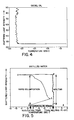
- the light beam Prior to the formation of cloud in the sample, the light beam is almost entirely reflected, and only a small amount of scattered light is detected by the detection unit 3; this is shown as a generally horizontal line in Fig 4.
- Fig 4 shows that this occurs between -27.5°C and -28°C. Therefore, by monitoring the light intensity received by the detector unit 3 as a function of temperature, the cloud point of the sample can be determined.
- the thermoelectric cooler is switched off to allow the temperature of the mirror to return to ambient. The unit is then depressurized and opened up to allow cleaning of the sample receptacle.
- the present invention has the following advantages:
- the apparatus has been described as using an open-topped receptacle, which is of course the most convenient.
- a receptacle with a transparent lid may be used for volatile liquids and to prevent drying during an experimental run.
- Figs. 5 to 12 show graphs of other experiments done with various systems.
- Figure 5 summarizes the results of an experiment with distilled water.
- the experiment started at point “A” where the liquid was cooled down slowly.
- the light scattering intensity did not increase as the temperature passed 0°C due to supercooling of the liquid.
- nucleation of ice occurred at point “B”, followed by a rapid crystal growth period and simultaneous release of latent heat.
- the fast release of latent heat caused the temperature of the system to rise to point "C”.
- Figures 6 and 7 show the results for other pure liquids, respectively cyclohexane and benzene.
- the melting points determined by the device agreed well with those reported in the literature as shown on the graphs.
- the latent heat effect was not apparent mainly because the latent heat of solidification of cyclohexane is very low (approximately 1/13 of that corresponding to water). It may be noted that due to supercooling effects it is usually only the melting point, and not the solidification point, which can be compared with literature values.
- Figure 8 shows the results for a 6% sodium chloride and water mixture. It can be seen that the melting point compares very well with the literature value.
- Figure 9 shows the results for an ethylene glycol-water system.
- the freezing and melting temperatures were distinctly measured even though the mixtures were translucent rather than transparent.
- the measured values for melting point compared well with the literature value.
- FIG 10. This is a system with 30% triethylamine and 70% water. According to the literature, the system is completely miscible at temperatures below about 18.5°C and becomes immiscible at temperatures higher than this level.
Landscapes
- Chemical & Material Sciences (AREA)
- Health & Medical Sciences (AREA)
- Engineering & Computer Science (AREA)
- Life Sciences & Earth Sciences (AREA)
- Medicinal Chemistry (AREA)
- Biochemistry (AREA)
- General Chemical & Material Sciences (AREA)
- Food Science & Technology (AREA)
- Chemical Kinetics & Catalysis (AREA)
- Physics & Mathematics (AREA)
- Analytical Chemistry (AREA)
- Oil, Petroleum & Natural Gas (AREA)
- General Health & Medical Sciences (AREA)
- General Physics & Mathematics (AREA)
- Immunology (AREA)
- Pathology (AREA)
- Investigating Or Analyzing Materials Using Thermal Means (AREA)
- Investigating Or Analysing Materials By Optical Means (AREA)
Claims (16)
- Verfahren zum Messen der Temperatur, bei der ein Übergang in einem Material zwischen einer transparenten oder lichtdurchlässigen Flüssigkeitsphase und einer lichtstreuenden Phase stattfindet, wobei das Verfahren folgende Schritte umfaßt:- Anordnen einer Probe des Materials in einem Behältnis (4, 17);- Aufstrahlen eines Lichtstrahls (2) auf die Probe in einer derartigen Weise, daß bei Nicht-Vorhandensein der lichtstreuenden Phase das Licht ohne wesentliche Streuung durch die Probe hindurchtritt;- Überwachen der Lichtstärke des von der Probe gestreuten Lichtstrahls unter Veränderung der Temperatur der Probe durch eine Temperaturänderungseinrichtung (6), während das Aufstrahlen des Lichtstrahls auf die Probe anhält;- Erfassen einer Veränderung der Lichtstärke des gestreuten Lichts und Bestimmen der Temperatur der Probe beim Auftreten einer solchen Veränderung der Lichtstärke;- dadurch gekennzeichnet, daß das Behältnis (4, 17) flach ist und einen Boden aus wärmeleitfähigem Material besitzt, der sich in Wärmekontakt mit der Temperaturänderungseinrichtung sowie auch mit einer Temperaturmeßeinrichtung (18) befindet, wobei der Boden eine obere Oberfläche (4) besitzt, die nicht-lichtstreuend ist, daß der Schritt des Aufstrahlens das Lenken des Lichtstrahls in einem derartigen Einfallswinkel auf die genannte obere Oberfläche beinhaltet, daß bei Nicht-Vorhandensein einer lichtstreuenden Phase das Licht des Strahls entweder größtenteils von der Oberfläche absorbiert wird oder entlang einer Lichtstrahlbahn reflektiert wird, und daß der Schritt des Überwachens das Konzentrieren des Lichts des von der Probe gestreuten Lichtstrahls durch eine Linse (22) hindurch auf wenigstens ein Lichterfassungselement (20) beinhaltet.
- Verfahren nach Anspruch 1,
bei dem es sich bei der genannten oberen Oberfläche (4) um eine ebene Spiegeloberfläche handelt, der Einfallswinkel zwischen dem Lichtstrahl und der genannten oberen Oberfläche ein spitzer Winkel von 20° bis 80° ist und bei dem das von der Probe im wesentlichen in rechtwinkliger Richtung zu der Oberfläche gestreute Licht detektiert wird. - Verfahren nach Anspruch 1 oder Anspruch 2,
bei dem die Tiefe der Flüssigkeitsprobe weniger als 1 cm ist. - Verfahren nach einem der vorausgehenden Ansprüche,
bei dem es sich bei der Temperaturänderungseinrichtung (18) um eine thermoelektrische Vorrichtung handelt. - Verfahren nach einem der vorausgehenden Ansprüche,
bei dem es sich bei dem Behältnis (4, 17) um ein flaches Behältnis mit einer offenen Oberseite handelt, wobei die genannte Oberfläche (4) einen im wesentlichen ebenen Boden bildet. - Verfahren nach einem der Ansprüche 1 bis 4,
bei dem die Flüssigkeit flüchtig ist und bei dem das Behältnis (4, 17) einen transparentes Oberteil aufweist, das sich zur Ermöglichung einer Reinigung abnehmen läßt. - Vorrichtung zum Messen der Temperatur, bei der ein Übergang in einem Material zwischen einer transparenten oder lichtdurchlässigen Flüssigkeitsphase und einer lichtstreuenden Phase stattfindet, mit- einer Kammer (1);- einem Flüssigkeitsprobenaufnahmebehältnis (4, 17) innerhalb der Kammer;- einer Einrichtung, die die Plazierung einer Probe des Materials in dem Behältnis ermöglicht und bei Abschluß der Untersuchung ein Entfernen der Probe ermöglicht;- einer Einrichtung zum Ändern der Temperatur (6) der Probe und einer Einrichtung zum Anzeigen der Temperatur (18) der Probe;- einer Lichtstrahlquelle (2), die zum Lenken eines Lichtstrahls in die Probe angeordnet ist;- einer Streulicht-Erfassungseinrichtung (3), die zum Erfassen von von der Probe gestreutem Licht und zum Erfassen von Veränderungen der Lichtstärke des Streulichts ausgelegt ist;- dadurch gekennzeichnet, daß die Kammer (1) im wesentlichen lichtdicht ist und lichtabsorbierende Innenflächen aufweist, daß das Behältnis (4, 17) einen Boden (4) aufweist, der durch ein wärmeleitfähiges Material mit einer nicht-lichstreuenden oberen Oberfläche (4) gebildet ist, wobei sich der Boden in Wärmekontakt mit der Einrichtung zum Ändern der Temperatur (6) und der Einrichtung zum Anzeigen der Temperatur (18) befindet, daß die Lichtstrahlquelle (2) derart angeordnet ist, daß sie den Strahl in einem derartigen Einfallswinkel auf die genannte obere Oberfläche richtet, daß Licht von dem Strahl von der genannten oberen Oberfläche größtenteils reflektiert oder absorbiert wird, und daß die Erfassungseinrichtung (3) eine Linse (22) beinhaltet, die das Licht von der Probe auf wenigstens ein Lichterfassungselement (20) konzentriert.
- Vorrichtung nach Anspruch 7,
mit einer Datenverarbeitungs- und Steuereinrichtung (7) zum Steuern der Änderung der Temperatur der genannten Oberfläche (4). - Vorrichtung nach Anspruch 7 oder Anspruch 8,
wobei es sich bei der genannten oberen Oberfläche (4) um eine ebene Spiegeloberfläche handelt, der Einfallswinkel zwischen dem Lichtstrahl und der oberen Oberfläche ein spitzer Winkel von 20° bis 80° ist und die Streulicht-Erfassungseinrichtung (3) entlang eines Lichtübertragungsweges angeordnet ist, der im wesentlichen rechtwinklig zu der genannten Oberfläche verläuft. - Vorrichtung nach einem der Ansprüche 7 bis 9,
wobei das Behältnis (4, 17) ein flaches Behältnis mit einer offenen Oberseite handelt, wobei die genannte Oberfläche (4) einen im wesentlichen flachen Boden bildet. - Vorrichtung nach einem der Ansprüche 7 bis 9,
bei der das Behältnis (4, 17) ein transparentes Oberteil aufweist, das sich zum Reinigen abnehmen läßt. - Vorrichtung nach einem der Ansprüche 7 bis 9,
bei der das Behältnis (4, 17) eine im Verhältnis zu seiner Breite geringe Tiefe besitzt. - Vorrichtung nach einem der Ansprüche 7 bis 12,
bei der die Einrichtung zum Ändern der Temperatur eine mit der genannten Oberfläche in Berührung befindliche thermoelektrische Kühleinrichtung (6) ist. - Vorrichtung nach einem der Ansprüche 7 bis 13,
bei der die Kammer (1) einen Einlaß (11) und einen Auslaß (12) für ein Trocknungsgas aufweist. - Vorrichtung nach einem der Ansprüche 7 bis 14,
bei der die Einrichtung zum Anzeigen der Temperatur der genannten Oberfläche eine mit der genannten Oberfläche (4) in direktem Kontakt befindliche, elektrische, wärmeempfindliche Vorrichtung (18) ist. - Vorrichtung nach einem der Ansprüche 7 bis 15,
bei der der Boden der Aufnahme (4, 17) in integraler Weise aus einem wärmeleitfähigen Metall gebildet ist.
Applications Claiming Priority (2)
| Application Number | Priority Date | Filing Date | Title |
|---|---|---|---|
| CA000558566A CA1316704C (en) | 1988-02-10 | 1988-02-10 | Method and apparatus for monitoring cloud point |
| CA558566 | 1988-02-10 |
Publications (3)
| Publication Number | Publication Date |
|---|---|
| EP0328334A2 EP0328334A2 (de) | 1989-08-16 |
| EP0328334A3 EP0328334A3 (en) | 1990-08-22 |
| EP0328334B1 true EP0328334B1 (de) | 1994-11-09 |
Family
ID=4137422
Family Applications (1)
| Application Number | Title | Priority Date | Filing Date |
|---|---|---|---|
| EP89301141A Expired - Lifetime EP0328334B1 (de) | 1988-02-10 | 1989-02-06 | Verfahren und Vorrichtung zur Überwachung des Trübungspunktes oder eines ähnlichen thermischen Überganges |
Country Status (5)
| Country | Link |
|---|---|
| US (1) | US5088833A (de) |
| EP (1) | EP0328334B1 (de) |
| JP (1) | JP2788046B2 (de) |
| CA (1) | CA1316704C (de) |
| DE (1) | DE68919240T2 (de) |
Cited By (2)
| Publication number | Priority date | Publication date | Assignee | Title |
|---|---|---|---|---|
| WO2003036295A1 (en) | 2001-10-19 | 2003-05-01 | Exxonmobil Research And Engineering Company | On-line determination of wax crystallization temperature of waxy solvent stream |
| US8236168B2 (en) | 2009-10-13 | 2012-08-07 | Exxonmobil Research And Engineering Company | Onset haze measurement apparatus and procedure |
Families Citing this family (34)
| Publication number | Priority date | Publication date | Assignee | Title |
|---|---|---|---|---|
| CA2025889C (en) * | 1990-09-20 | 2001-04-17 | Victoria Shien-Fern Ker | Pour point detection |
| NO176156C (no) * | 1992-06-22 | 1995-02-08 | Norsk Hydro As | Fremgangsmåte for bestemmelse av voksutfellingstemperatur og megnde voks i råolje e.l. |
| WO1994024544A1 (fr) * | 1993-04-15 | 1994-10-27 | Japan Energy Corporation | Procede et instrument de mesure du point de trouble |
| US5651614A (en) * | 1995-01-20 | 1997-07-29 | Betzdearborn Inc. | Cloud point and pour point analyzer |
| US5769539A (en) * | 1995-08-07 | 1998-06-23 | Phase Technology | Backflush system for a filter membrane located upstream of a hydrocarbon analyzer apparatus |
| US5827952A (en) * | 1996-03-26 | 1998-10-27 | Sandia National Laboratories | Method of and apparatus for determining deposition-point temperature |
| US5661233A (en) * | 1996-03-26 | 1997-08-26 | Sandia Corporation | Acoustic-wave sensor apparatus for analyzing a petroleum-based composition and sensing solidification of constituents therein |
| US6039471A (en) * | 1996-05-22 | 2000-03-21 | Integrated Device Technology, Inc. | Device for simulating dissipation of thermal power by a board supporting an electronic component |
| ATE288585T1 (de) * | 1996-07-03 | 2005-02-15 | Japan Energy Corp | Gefrierpunktmessgerät und verfahren zur messung des gefrierpunktes |
| US6827484B2 (en) * | 2002-07-09 | 2004-12-07 | Charles Y. Tsang | Cloud point monitoring device |
| FR2846748B1 (fr) * | 2002-10-30 | 2005-04-22 | I S L | Procede de determination du point de disparition des cristaux de produits petroliers ainsi que dispositif permettant la mise en oeuvre de ce procede |
| US7058511B2 (en) * | 2003-11-24 | 2006-06-06 | The Boeing Company | Sub-visible cloud cover assessment: VNIR-SWIR |
| US7184890B2 (en) * | 2003-11-24 | 2007-02-27 | The Boeing Company | Cloud shadow detection: VNIR-SWIR |
| US6990410B2 (en) * | 2003-11-24 | 2006-01-24 | The Boeing Company | Cloud cover assessment: VNIR-SWIR |
| US7875458B2 (en) * | 2003-11-25 | 2011-01-25 | Exxonmobil Research And Engineering Company | Application of test for residual wax contamination in basestocks to correlate with the low temperature viscometric properties of fully formulated oils |
| US7736051B2 (en) * | 2004-03-30 | 2010-06-15 | Yamatake Corporation | Thermoelectric device and mirror surface state detection device |
| US6881760B1 (en) * | 2004-07-16 | 2005-04-19 | Chevron U.S.A. Inc. | Methods for monitoring solids content in Fischer-Tropsch products |
| DE102004038397B3 (de) * | 2004-08-06 | 2006-04-13 | Bartec Gmbh | Vorrichtung zum Bestimmen der Taupunkttemperatur eines Messgases |
| GB0418555D0 (en) * | 2004-08-19 | 2004-09-22 | Michell Instr Ltd | Apparatus for measuring dew point of a gas stream |
| US7182509B2 (en) * | 2005-04-27 | 2007-02-27 | Advanced Instruments, Inc. | Nanoliter osmometer and method of operation |
| KR20080075096A (ko) * | 2005-09-22 | 2008-08-14 | 아반티움 인터내셔날 비.브이. | 용해도 커브 및 준안정 영역 결정을 위한 시스템 및 방법 |
| DE102006013726A1 (de) * | 2006-03-24 | 2007-09-27 | Bartec Gmbh | Verfahren und Sensor zum Bestimmen des Kohlenwasserstoff-Taupunktes in einem Gas |
| US8113708B2 (en) * | 2008-07-16 | 2012-02-14 | GM Global Technology Operations LLC | Cloud point monitoring systems for determining a cloud point temperature of diesel fuel |
| US8292497B2 (en) | 2008-07-16 | 2012-10-23 | GM Global Technology Operations LLC | Cloud point monitoring systems for determining a cloud point temperature of diesel fuel |
| US8128279B2 (en) * | 2008-07-16 | 2012-03-06 | GM Global Technology Operations LLC | Cloud point monitoring systems for determining a cloud point temperature of diesel fuel |
| US8753007B2 (en) * | 2010-08-17 | 2014-06-17 | Honeywell Asca Inc. | Fuel cloud point or freeze point sensor with collinear optical geometry |
| CN103076332A (zh) * | 2013-01-11 | 2013-05-01 | 中国电子科技集团公司第十一研究所 | 一种用于测量汽化时间的系统 |
| GB2526772B (en) * | 2014-03-27 | 2017-07-26 | Analytical Tech & Control Ltd | Cloud point measurement in fuels |
| US9354167B2 (en) * | 2014-10-07 | 2016-05-31 | Phase Technology | Method and apparatus for measuring appearance and disappearance temperatures of wax for transparent, translucent and opaque oils |
| FR3035967B1 (fr) * | 2015-05-05 | 2017-06-16 | Syntilab | Dispositif pour mesurer l'activite de l'eau d'echantillons solides ou liquides |
| US11067521B2 (en) * | 2017-09-17 | 2021-07-20 | Anv Laser Industry Ltd. | Apparatus and methods for measuring thermal transformation |
| CN111220795A (zh) * | 2018-11-26 | 2020-06-02 | 山东蓝星东大有限公司 | 聚醚多元醇浊点的测试方法 |
| CN112881457B (zh) * | 2021-01-18 | 2022-04-12 | 东南大学 | 一种控温微乳液相图的自动化检测装置及方法 |
| EP4484854A1 (de) * | 2023-06-27 | 2025-01-01 | Bluefors Oy | Kryogene kühlvorrichtung und verfahren zur kryogenischen kühlung einer probe |
Family Cites Families (34)
| Publication number | Priority date | Publication date | Assignee | Title |
|---|---|---|---|---|
| US3077764A (en) * | 1959-10-30 | 1963-02-19 | Standard Oil Co | Pour point instrument |
| GB966828A (en) * | 1963-02-04 | 1964-08-19 | Standard Oil Co | Improvements in or relating to pour point instruments |
| US3248928A (en) * | 1960-03-08 | 1966-05-03 | Exxon Research Engineering Co | Pour point apparatus |
| US3112648A (en) * | 1961-12-11 | 1963-12-03 | George A Dulk | Peltier dew point hygrometer |
| NL287768A (de) * | 1962-02-05 | |||
| US3269185A (en) * | 1963-01-28 | 1966-08-30 | Cambridge Systems Inc | Dewpoint sensing structure |
| BE638309A (de) * | 1963-10-08 | |||
| GB1029165A (en) * | 1964-07-28 | 1966-05-11 | Shell Int Research | Method and apparatus for measuring cloud point temperatures |
| FR1417250A (fr) * | 1964-09-28 | 1965-11-12 | Cie De Raffinage Shell Berre | Procédé et appareil pour la mesure du point de trouble de liquides |
| DE1299437B (de) * | 1965-09-07 | 1969-07-17 | Schaefer Bruno | Spiegel zur Messung des Taupunktes von Gasen |
| GB1197568A (en) * | 1966-09-27 | 1970-07-08 | British Petroleum Co | Detector for Detecting the End Point in Cloud Point Determination and an Apparatus Comprising It |
| US3528278A (en) * | 1967-09-05 | 1970-09-15 | Technology Inc | Method and apparatus for determining the presence of vapor in a gas |
| US3580047A (en) * | 1967-11-24 | 1971-05-25 | Shell Oil Co | Pour and cloud point analyzer |
| US3545254A (en) * | 1968-02-13 | 1970-12-08 | Shell Oil Co | Cloud point detector |
| FR1576543A (de) * | 1968-05-22 | 1969-08-01 | ||
| US3623356A (en) * | 1969-12-18 | 1971-11-30 | Eg & G Inc | Dew point hygrometer |
| US3643492A (en) * | 1970-04-21 | 1972-02-22 | Shell Oil Co | Pour and cloud point analyzer |
| US3807865A (en) * | 1970-12-18 | 1974-04-30 | M Gordon | Process and apparatus for determination of spinodal and critical points or loci associated with phase transition |
| GB1438754A (en) * | 1972-03-01 | 1976-06-09 | Mectron Frigistor Ltd | Cloud point detector |
| GB1554879A (en) * | 1975-09-29 | 1979-10-31 | Univ Sydney | Phase transition detector |
| JPS5312232U (de) * | 1976-07-15 | 1978-02-01 | ||
| SU645069A1 (ru) * | 1977-07-01 | 1979-01-30 | Предприятие П/Я Р-6205 | Способ определени точки росы |
| DE2945445A1 (de) * | 1978-11-22 | 1980-06-04 | Protimeter Ltd | Verfahren und vorrichtung zur bestimmung des taupunktes |
| GB2036339B (en) * | 1978-11-22 | 1983-01-06 | Protimeter Ltd | Measuring dew point |
| GB2043242A (en) * | 1979-02-14 | 1980-10-01 | Protimeter Ltd | Dew point meter |
| SU851221A1 (ru) * | 1979-07-16 | 1981-07-30 | Московский Ордена Ленина Энергетическийинститут | Способ определени температурыКРиСТАллизАции ХАльКОгЕНидНыХ СТЕКОл |
| US4519717A (en) * | 1982-06-07 | 1985-05-28 | Gca Corporation | On-stream cloud point analyzer |
| DE3247689A1 (de) * | 1982-12-23 | 1984-06-28 | Horst Dipl.-Ing. Linn (FH), 8459 Hirschbach | Verfahren zum erfassen des schmelzens von materialien sowie vorrichtung zur durchfuehrung des verfahrens |
| US4629333A (en) * | 1984-10-19 | 1986-12-16 | Eg&G, Inc. | Chilled mirror hygrometer with performance monitoring |
| SU1276976A1 (ru) * | 1984-12-12 | 1986-12-15 | Главная геофизическая обсерватория им.А.И.Воейкова | Гигрометр точки росы |
| JPS61198045A (ja) * | 1985-02-28 | 1986-09-02 | Matsushita Electric Ind Co Ltd | 表面汚染度観察方法 |
| GB8514584D0 (en) * | 1985-06-10 | 1985-07-10 | Shell Int Research | Measuring dew-point of gas stream |
| GB8701616D0 (en) * | 1987-01-26 | 1987-03-04 | Michell Instr Ltd | Dewpoint meter |
| GB8703185D0 (en) * | 1987-02-12 | 1987-03-18 | Keene B R T | Melting point apparatus |
-
1988
- 1988-02-10 CA CA000558566A patent/CA1316704C/en not_active Expired - Lifetime
-
1989
- 1989-02-06 EP EP89301141A patent/EP0328334B1/de not_active Expired - Lifetime
- 1989-02-06 DE DE68919240T patent/DE68919240T2/de not_active Expired - Lifetime
- 1989-02-09 JP JP1030921A patent/JP2788046B2/ja not_active Expired - Lifetime
- 1989-12-21 US US07/454,270 patent/US5088833A/en not_active Expired - Lifetime
Cited By (2)
| Publication number | Priority date | Publication date | Assignee | Title |
|---|---|---|---|---|
| WO2003036295A1 (en) | 2001-10-19 | 2003-05-01 | Exxonmobil Research And Engineering Company | On-line determination of wax crystallization temperature of waxy solvent stream |
| US8236168B2 (en) | 2009-10-13 | 2012-08-07 | Exxonmobil Research And Engineering Company | Onset haze measurement apparatus and procedure |
Also Published As
| Publication number | Publication date |
|---|---|
| EP0328334A2 (de) | 1989-08-16 |
| CA1316704C (en) | 1993-04-27 |
| JP2788046B2 (ja) | 1998-08-20 |
| EP0328334A3 (en) | 1990-08-22 |
| DE68919240T2 (de) | 1995-06-14 |
| US5088833A (en) | 1992-02-18 |
| DE68919240D1 (de) | 1994-12-15 |
| JPH02263144A (ja) | 1990-10-25 |
Similar Documents
| Publication | Publication Date | Title |
|---|---|---|
| EP0328334A2 (de) | Verfahren und Vorrichtung zur Überwachung des Trübungspunktes oder eines ähnlichen thermischen Überganges | |
| Araki et al. | Measurements of thermophysical properties of sodium acetate hydrate | |
| CA1280910C (en) | Dew point analyzer | |
| US3457772A (en) | Automatic cloud point detector | |
| US9354167B2 (en) | Method and apparatus for measuring appearance and disappearance temperatures of wax for transparent, translucent and opaque oils | |
| US3161039A (en) | Apparatus for determining pour point | |
| EP1230553B1 (de) | Chemischer oder biologischer analysator mit reaktionstemperaturanpassung | |
| US4465554A (en) | Hot jet evaporator | |
| US3077764A (en) | Pour point instrument | |
| EP0723155A3 (de) | Verfahren und Vorrichtung zur Bestimmung des Trübungspunktes und des Stockpunktes einer Erdölfraktion | |
| EP0259307B1 (de) | Regelung der verdampfung im labor | |
| US5090817A (en) | Pour point detection | |
| EP0192551B1 (de) | Verfahren und Vorrichtung zur Bestimmung des Schmelzpunkts von Karbureaktoren | |
| US3447358A (en) | Method and apparatus for measuring cloud point temperatures | |
| Nozaki et al. | Application of liquid-crystal thermometry to drop temperature measurements | |
| FI95750C (fi) | Menetelmä ja laite öljyn samepisteen mittaamiseksi | |
| Lepault et al. | Freezing of aqueous specimens: An X‐ray diffraction study | |
| Boston et al. | Effect of Melting on the Electronic Spectra of Cs3NiCl5 and CsNiCl3 | |
| US3514993A (en) | Apparatus and method for automatic crystal point detection | |
| US3027750A (en) | Apparatus for studying phase relationships of gases and gas mixtures | |
| US3496760A (en) | Method and apparatus for determining the pour point of liquids | |
| JPH01229950A (ja) | 相変化の臨界値測定方法及びその装置 | |
| EP0257806B1 (de) | Taupunktanalysegerät | |
| JP2557456Y2 (ja) | 液温直接測定式温度変化型屈折率測定装置 | |
| Woollam | VASE |
Legal Events
| Date | Code | Title | Description |
|---|---|---|---|
| PUAI | Public reference made under article 153(3) epc to a published international application that has entered the european phase |
Free format text: ORIGINAL CODE: 0009012 |
|
| AK | Designated contracting states |
Kind code of ref document: A2 Designated state(s): CH DE FR GB IT LI NL |
|
| PUAL | Search report despatched |
Free format text: ORIGINAL CODE: 0009013 |
|
| AK | Designated contracting states |
Kind code of ref document: A3 Designated state(s): CH DE FR GB IT LI NL |
|
| 17P | Request for examination filed |
Effective date: 19901210 |
|
| RAP3 | Party data changed (applicant data changed or rights of an application transferred) |
Owner name: NOVA HUSKY RESEARCH CORPORATION |
|
| 17Q | First examination report despatched |
Effective date: 19920826 |
|
| RAP1 | Party data changed (applicant data changed or rights of an application transferred) |
Owner name: NOVACOR RESEARCH & TECHNOLOGY CORPORATION |
|
| GRAA | (expected) grant |
Free format text: ORIGINAL CODE: 0009210 |
|
| AK | Designated contracting states |
Kind code of ref document: B1 Designated state(s): CH DE FR GB IT LI NL |
|
| REF | Corresponds to: |
Ref document number: 68919240 Country of ref document: DE Date of ref document: 19941215 |
|
| ET | Fr: translation filed | ||
| ITF | It: translation for a ep patent filed | ||
| PLBE | No opposition filed within time limit |
Free format text: ORIGINAL CODE: 0009261 |
|
| STAA | Information on the status of an ep patent application or granted ep patent |
Free format text: STATUS: NO OPPOSITION FILED WITHIN TIME LIMIT |
|
| 26N | No opposition filed | ||
| REG | Reference to a national code |
Ref country code: GB Ref legal event code: IF02 |
|
| PGFP | Annual fee paid to national office [announced via postgrant information from national office to epo] |
Ref country code: CH Payment date: 20080129 Year of fee payment: 20 |
|
| PGFP | Annual fee paid to national office [announced via postgrant information from national office to epo] |
Ref country code: DE Payment date: 20080131 Year of fee payment: 20 Ref country code: IT Payment date: 20080226 Year of fee payment: 20 Ref country code: GB Payment date: 20080206 Year of fee payment: 20 Ref country code: NL Payment date: 20080103 Year of fee payment: 20 |
|
| REG | Reference to a national code |
Ref country code: CH Ref legal event code: PFA Owner name: NOVACOR RESEARCH & TECHNOLOGY CORPORATION Free format text: NOVACOR RESEARCH & TECHNOLOGY CORPORATION#801 - 7TH AVENUE S.W.#CALGARY/ALBERTA (CA) -TRANSFER TO- NOVACOR RESEARCH & TECHNOLOGY CORPORATION#801 - 7TH AVENUE S.W.#CALGARY/ALBERTA (CA) |
|
| PGFP | Annual fee paid to national office [announced via postgrant information from national office to epo] |
Ref country code: FR Payment date: 20080208 Year of fee payment: 20 |
|
| REG | Reference to a national code |
Ref country code: CH Ref legal event code: PL |
|
| REG | Reference to a national code |
Ref country code: GB Ref legal event code: PE20 Expiry date: 20090205 |
|
| NLV7 | Nl: ceased due to reaching the maximum lifetime of a patent |
Effective date: 20090206 |
|
| PG25 | Lapsed in a contracting state [announced via postgrant information from national office to epo] |
Ref country code: NL Free format text: LAPSE BECAUSE OF EXPIRATION OF PROTECTION Effective date: 20090206 |
|
| PG25 | Lapsed in a contracting state [announced via postgrant information from national office to epo] |
Ref country code: GB Free format text: LAPSE BECAUSE OF EXPIRATION OF PROTECTION Effective date: 20090205 |