EP0328472A2 - Anlasser-Verbindungsstück für die stufenlose Druckzufuhr in pneumatischen Anlagen - Google Patents
Anlasser-Verbindungsstück für die stufenlose Druckzufuhr in pneumatischen Anlagen Download PDFInfo
- Publication number
- EP0328472A2 EP0328472A2 EP89460004A EP89460004A EP0328472A2 EP 0328472 A2 EP0328472 A2 EP 0328472A2 EP 89460004 A EP89460004 A EP 89460004A EP 89460004 A EP89460004 A EP 89460004A EP 0328472 A2 EP0328472 A2 EP 0328472A2
- Authority
- EP
- European Patent Office
- Prior art keywords
- valve
- seat
- rod
- starter
- hollow screw
- Prior art date
- Legal status (The legal status is an assumption and is not a legal conclusion. Google has not performed a legal analysis and makes no representation as to the accuracy of the status listed.)
- Granted
Links
Images

Classifications
-
- F—MECHANICAL ENGINEERING; LIGHTING; HEATING; WEAPONS; BLASTING
- F16—ENGINEERING ELEMENTS AND UNITS; GENERAL MEASURES FOR PRODUCING AND MAINTAINING EFFECTIVE FUNCTIONING OF MACHINES OR INSTALLATIONS; THERMAL INSULATION IN GENERAL
- F16K—VALVES; TAPS; COCKS; ACTUATING-FLOATS; DEVICES FOR VENTING OR AERATING
- F16K31/00—Actuating devices; Operating means; Releasing devices
- F16K31/12—Actuating devices; Operating means; Releasing devices actuated by fluid
- F16K31/36—Actuating devices; Operating means; Releasing devices actuated by fluid in which fluid from the circuit is constantly supplied to the fluid motor
- F16K31/363—Actuating devices; Operating means; Releasing devices actuated by fluid in which fluid from the circuit is constantly supplied to the fluid motor the fluid acting on a piston
-
- F—MECHANICAL ENGINEERING; LIGHTING; HEATING; WEAPONS; BLASTING
- F15—FLUID-PRESSURE ACTUATORS; HYDRAULICS OR PNEUMATICS IN GENERAL
- F15B—SYSTEMS ACTING BY MEANS OF FLUIDS IN GENERAL; FLUID-PRESSURE ACTUATORS, e.g. SERVOMOTORS; DETAILS OF FLUID-PRESSURE SYSTEMS, NOT OTHERWISE PROVIDED FOR
- F15B11/00—Servomotor systems without provision for follow-up action ; Circuits therefor
- F15B11/06—Servomotor systems without provision for follow-up action ; Circuits therefor involving features specific to the use of a compressible medium, e.g. air, steam
- F15B11/068—Servomotor systems without provision for follow-up action ; Circuits therefor involving features specific to the use of a compressible medium, e.g. air, steam with valves for gradually putting pneumatic systems under pressure
-
- F—MECHANICAL ENGINEERING; LIGHTING; HEATING; WEAPONS; BLASTING
- F16—ENGINEERING ELEMENTS AND UNITS; GENERAL MEASURES FOR PRODUCING AND MAINTAINING EFFECTIVE FUNCTIONING OF MACHINES OR INSTALLATIONS; THERMAL INSULATION IN GENERAL
- F16K—VALVES; TAPS; COCKS; ACTUATING-FLOATS; DEVICES FOR VENTING OR AERATING
- F16K17/00—Safety valves; Equalising valves, e.g. pressure relief valves
- F16K17/02—Safety valves; Equalising valves, e.g. pressure relief valves opening on surplus pressure on one side; closing on insufficient pressure on one side
- F16K17/04—Safety valves; Equalising valves, e.g. pressure relief valves opening on surplus pressure on one side; closing on insufficient pressure on one side spring-loaded
- F16K17/0446—Safety valves; Equalising valves, e.g. pressure relief valves opening on surplus pressure on one side; closing on insufficient pressure on one side spring-loaded with an obturating member having at least a component of their opening and closing motion not perpendicular to the closing faces
- F16K17/046—Safety valves; Equalising valves, e.g. pressure relief valves opening on surplus pressure on one side; closing on insufficient pressure on one side spring-loaded with an obturating member having at least a component of their opening and closing motion not perpendicular to the closing faces the valve being of the gate valve type or the sliding valve type
-
- F—MECHANICAL ENGINEERING; LIGHTING; HEATING; WEAPONS; BLASTING
- F16—ENGINEERING ELEMENTS AND UNITS; GENERAL MEASURES FOR PRODUCING AND MAINTAINING EFFECTIVE FUNCTIONING OF MACHINES OR INSTALLATIONS; THERMAL INSULATION IN GENERAL
- F16K—VALVES; TAPS; COCKS; ACTUATING-FLOATS; DEVICES FOR VENTING OR AERATING
- F16K2200/00—Details of valves
- F16K2200/40—Bleeding means in closed position of the valve, e.g. bleeding passages
-
- Y—GENERAL TAGGING OF NEW TECHNOLOGICAL DEVELOPMENTS; GENERAL TAGGING OF CROSS-SECTIONAL TECHNOLOGIES SPANNING OVER SEVERAL SECTIONS OF THE IPC; TECHNICAL SUBJECTS COVERED BY FORMER USPC CROSS-REFERENCE ART COLLECTIONS [XRACs] AND DIGESTS
- Y10—TECHNICAL SUBJECTS COVERED BY FORMER USPC
- Y10T—TECHNICAL SUBJECTS COVERED BY FORMER US CLASSIFICATION
- Y10T137/00—Fluid handling
- Y10T137/7722—Line condition change responsive valves
- Y10T137/7781—With separate connected fluid reactor surface
- Y10T137/7835—Valve seating in direction of flow
-
- Y—GENERAL TAGGING OF NEW TECHNOLOGICAL DEVELOPMENTS; GENERAL TAGGING OF CROSS-SECTIONAL TECHNOLOGIES SPANNING OVER SEVERAL SECTIONS OF THE IPC; TECHNICAL SUBJECTS COVERED BY FORMER USPC CROSS-REFERENCE ART COLLECTIONS [XRACs] AND DIGESTS
- Y10—TECHNICAL SUBJECTS COVERED BY FORMER USPC
- Y10T—TECHNICAL SUBJECTS COVERED BY FORMER US CLASSIFICATION
- Y10T137/00—Fluid handling
- Y10T137/7722—Line condition change responsive valves
- Y10T137/7837—Direct response valves [i.e., check valve type]
- Y10T137/7847—With leak passage
-
- Y—GENERAL TAGGING OF NEW TECHNOLOGICAL DEVELOPMENTS; GENERAL TAGGING OF CROSS-SECTIONAL TECHNOLOGIES SPANNING OVER SEVERAL SECTIONS OF THE IPC; TECHNICAL SUBJECTS COVERED BY FORMER USPC CROSS-REFERENCE ART COLLECTIONS [XRACs] AND DIGESTS
- Y10—TECHNICAL SUBJECTS COVERED BY FORMER USPC
- Y10T—TECHNICAL SUBJECTS COVERED BY FORMER US CLASSIFICATION
- Y10T137/00—Fluid handling
- Y10T137/7722—Line condition change responsive valves
- Y10T137/7837—Direct response valves [i.e., check valve type]
- Y10T137/7847—With leak passage
- Y10T137/7849—Bypass in valve casing
-
- Y—GENERAL TAGGING OF NEW TECHNOLOGICAL DEVELOPMENTS; GENERAL TAGGING OF CROSS-SECTIONAL TECHNOLOGIES SPANNING OVER SEVERAL SECTIONS OF THE IPC; TECHNICAL SUBJECTS COVERED BY FORMER USPC CROSS-REFERENCE ART COLLECTIONS [XRACs] AND DIGESTS
- Y10—TECHNICAL SUBJECTS COVERED BY FORMER USPC
- Y10T—TECHNICAL SUBJECTS COVERED BY FORMER US CLASSIFICATION
- Y10T137/00—Fluid handling
- Y10T137/8158—With indicator, register, recorder, alarm or inspection means
- Y10T137/8225—Position or extent of motion indicator
- Y10T137/8275—Indicator element rigidly carried by the movable element whose position is indicated
-
- Y—GENERAL TAGGING OF NEW TECHNOLOGICAL DEVELOPMENTS; GENERAL TAGGING OF CROSS-SECTIONAL TECHNOLOGIES SPANNING OVER SEVERAL SECTIONS OF THE IPC; TECHNICAL SUBJECTS COVERED BY FORMER USPC CROSS-REFERENCE ART COLLECTIONS [XRACs] AND DIGESTS
- Y10—TECHNICAL SUBJECTS COVERED BY FORMER USPC
- Y10T—TECHNICAL SUBJECTS COVERED BY FORMER US CLASSIFICATION
- Y10T137/00—Fluid handling
- Y10T137/8593—Systems
- Y10T137/87265—Dividing into parallel flow paths with recombining
- Y10T137/87378—Second valve assembly carried by first valve head
Definitions
- the present invention relates to starter connectors for the progressive pressurization of pneumatic installations. It relates more particularly to such starter-couplings to be fixed on pneumatic receiver or transmitter components.
- the present invention of starter couplings makes it possible to avoid these drawbacks by making two different versions of apparatus with regard to their use, but which both replace the traditional couplings for which they are substituted while ensuring the function of a starter.
- the first version of these devices is intended to be screwed on pneumatic components receivers, such as distributors, the fluid arriving through the piping which is connected to them.
- the devices of the second version are intended to be screwed onto pneumatic emitting components, such as the shut-off and purge valves called disconnectors, the air flow exiting in this case through the piping which is connected to them.
- the connector-starter according to the invention is in the form of a square connector called “banjo”, comprising a module equipped with piping connection means, this module being orientable around a hollow screw at the time of the fitting of the fitting, and interchangeable depending on the nature and the diameter of this piping to be connected.
- the hollow screw comprises the means for filling at a reduced and controlled flow rate of the downstream installation, established in derivation of a seat closed at rest by a valve and constituting the main passage through the device; valve requested to close by a slight return spring of insignificant force with respect to the forces brought into play by the pressures and just sufficient to overcome friction.
- the valve is secured to a rod of smaller section extending in the opposite direction from the seat towards the end of the hollow screw opposite its threaded fixing end.
- the free end of this rod is in the atmosphere beyond a seal in which it slides and is guided in the bore of a plug for retaining this seal which closes the device.
- the return spring bears on the plug and on a shoulder of the valve.
- the cylindrical wall of the hollow screw is pierced with peripheral holes ensuring, when the valve is open, the full passage of the fluid between the threaded orifice and the annular chamber of the orientable module in connection with the piping.
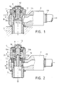
- the connector-starter is composed of a module 2 comprising an orifice 13 for connecting a pipe through which the compressed air arrives, and a hollow screw 1 around which it can be oriented.
- An annular distribution chamber 14 is formed between the module 2 and the hollow screw 1 and allows the connection between the piping and the interior of the hollow screw by a series of peripheral holes 8 made in its wall.
- the hollow screw 1 has a threaded orifice 7 constituting in this version the outlet, capable of being screwed into the supply orifice of a receiving apparatus, and separated from the holes 8 by a valve 3 closing its seat 3a at rest by the force of a return spring 5.
- the valve 3 is integral with a rod 4 extending in the direction opposite to its bearing face, through a seal 6 with double lip with U-profile.
- the end of the rod 4 beyond the seal 6 is in the atmosphere and guided in a bore 10 of a plug 9 which closes the device and on which the seal 6 is applied.
- the spring 5 works in extension and is supported by one end in the hollow of the profile of the seal 6, and the other on the shoulder 22 formed by the junction of the valve 3 and its rod 4 of smaller section.
- the static seal 6, the outer lip of which is in contact with the internal wall of the hollow screw 1 delimits with the valve 3 closing its seat 3a a chamber 11 open on the annular chamber 14 by the peripheral holes 8.
- the valve 3 is pierced axially on its bearing face with a channel 15 in connection with a calibrated radial channel 16 leading to the chamber 14.
- the pressure P1 in the chamber 11 acts to close the valve 3 by its action on the difference in the cross-sections of the valve and its rod in the joint 6.
- the pressure P2 downstream acts in opening the valve by its action on its full section.
- the valve 3 opens, releasing the full passage.
- the rod 4 has at its free end a narrowing 12 which protrudes out of the device when the valve is opened and serves as a visual indicator.
- this version differs mainly from the previous version according to FIG. 1 by the fact that the hollow screw 1 has an additional seal 6b with double U-profile lip which takes support on the shoulder 22 at the junction of the valve 3 with its rod 4, and the outer lip of which can slide in leaktight manner on the internal cylindrical wall of the hollow screw 1.
- the seal 6b delimits with the static seal 6a a first chamber 11a open on the bearing face of the valve 3 and the inlet orifice 7 by an axial channel 20 in connection with a radial channel 21 formed in the valve-stem assembly.
- the pressure P1 of the network flows through a calibrated hole 18 made in the wall of the hollow screw 1 between the inlet orifice 7 and the valve 3, to open into the annular chamber 14 and gradually fill the downstream installation with increasing pressure P2.
- the pressure P1 acts on opening the valve 3 on its full section and on closing by its action in the chamber 11a on the annular section resulting from the difference in the outside diameter of the seal 6b and the inside diameter of the seal 6a.
- the downstream pressure P2 acts at the opening of the valve by its action on the annular section resulting from the difference between the outside diameter of the seal 6b and that of the valve 3 on its seat 3a.
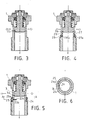
- Fig. 3 shows another means of establishing a reduced progressive filling rate of fixed value bypassing the main passage 3a: according to FIG. 3, a groove 17 of calibrated width and depth is formed on the bearing surface of the valve 3 on its seat 3a.
- Figs. 4, 5 and 6 show different means of establishing a reduced progressive filling rate of variable value, bypassing the main passage 3a, means more particularly but not exclusively applicable to the version of devices described according to FIG. 1.
- circular grooves 27 and 27a are formed on the outer wall of the hollow screw 1 at the level of the annular chamber 14 of the orientable module 2.
- the wall of the hollow screw is traversed by different calibrated holes 29 and 29a, each of them starting from the bottom of their respective grooves 27 and 27a.
- the mounting of an O-ring 28 in the groove 27a masks the hole 29a, allowing the passage of fluid at reduced flow rate through the single hole 29.
- a rubber ring 24 surrounds the outer wall of the hollow screw 1 at the level of the annular chamber 14 of the module 2.
- This ring 24 has a hole 25 which can be matched, by rotation of the ring, with one a plurality of different calibrated holes 23a, 23b, 23c made in the wall of the hollow screw and establishing the connection between the threaded orifice 7 and the annular chamber 14, these holes being smaller than the hole 25.
- Fig. 6 shows in cross section AA ′ a variant of the previous method according to FIG. 5, according to which the hole 25 of the ring 24 can be adjusted to any point of a semicircular groove 26a extending on either side of a single hole 26 in the wall of the hollow screw 1, and whose depth and / or width are gradually decreasing away from the hole.
- Figs. 7 and 8 show means of establishing a reduced progressive filling rate of variable value bypassing the main passage 3a, means more especially but not exclusively applicable to the version of apparatus according to FIG. 2.
- the interior of the threaded inlet orifice 7 of the hollow screw 1 receives a threaded ring 31 which can be screwed into it using an appropriate tool.
- the end of this ring 31 can partially mask, at will, a hole 30 establishing the connection between the threaded orifice 7 and the annular chamber 14 of the module 2.
- the threaded orifice 7 comprises a semi-circular elastic ring 33, capable of being adjusted in rotation in a retaining groove using a suitable tool, so as to unmask by the play between its ends only a hole 32, 32a or 32b formed in the wall of the hollow screw and establishing the connection between the threaded orifice 7 and the annular chamber 14 of the module 2.
- Fig. 7 also illustrates another means of establishing the seal between the chamber 11a and the chamber 11b, using an O-ring 36b mounted in a peripheral groove of the valve 3 instead of the double lip seal 6b.
- Figs. 1 and 2 it can be noted that the two versions of starter couplings are not differentiate only by the presence of an additional seal and channels 20 and 21 of the stem-valve assembly.
- the realization of the two types of apparatus in the same size can therefore be done from common elements, such as the plug 9 and the hollow screw 1, the dimensions of which would be those of the apparatus belonging to the version described according to FIG. . 2.
- the presence of a seal for the valve 3 on its seat 3a is not essential, a slight leak at this level only resulting in increasing the value of the reduced flow rate, without prejudice to the perfect functioning of the device.
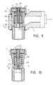
- a flat seal 37 replaces the double lip seal 6 of FIG. 1.
- the flat seal 37 is clamped between the hollow screw 1 and the plug 9, without ensuring the seal around the rod 4.
- the shoulder formed by the narrowing of the rod 4 has a circular peripheral surface 38 which is applied to the seal 37 when the valve is opened.
- Fig. 9 also illustrates, as well as FIG. 10, other means for establishing a reduced progressive filling rate of variable value, applicable to the version of devices to be fixed on a receiving component. These means have the advantage of allowing adjustment by the end of the valve stem.
- valve-stem assembly is traversed by an axial channel 39, the lower part of which is tapped.
- a conduit opens radial 40 open at its other end on the chamber 11 communicating through the holes 8 with the chamber 14.
- a rod 41 provided with a seal 42, the lower end, slightly bevelled, more or minus the orifice of the radial duct 40.
- valve-stem assembly has an axial bore 43 open at the upper end of the rod 4, and the lower end of which is flared.
- one open one or more lateral conduits 44 open on the orifice of the hollow screw 1, and an axial conduit 45 communicating with a radial conduit 46 opened by a hole 8 on the annular chamber 14.
- a rod 47 provided with a seal 48, the lower end of which forms a needle 49 engaged in the orifice of the conduit 45 to close it more or less.
- the compressed air arriving through the holes 8 passes through the conduits 46 and 45, then through the conduit (s) 44.
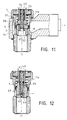
- the starter connector of Fig. 11 is of the type to be fixed on a transmitting element, the compressed air arriving through the orifice of the hollow screw 1. Like the connector-starter of FIG. 9, it comprises a flat seal 37 surrounding the rod 4 at the upper end of the chamber 11a which, during progressive filling, presents a slight leak around the top of the rod 4, until the valve opens, for which the bearing surface 38 comes into contact on the seal 37.
- Fig. 11 also illustrates, as well as FIG. 12, means for establishing a reduced filling rate of variable value, applicable to the version of devices to be fixed on a transmitter component.
- valve-stem assembly is traversed by an upper bore 50 extended by a bore lower 51 of larger diameter.
- a radial duct 52 leads from the bore 50 to the chamber 14 via a hole 8, while one or more channels 53 of axial direction lead from the bottom of the bore 51 to the chamber 11a.
- a rod 54 provided with a seal 55, the lower end of which, slightly bevelled, more or less obstructs the orifice of the conduit 52.
- valve-stem assembly has the same arrangement as that of FIG. 10, with a needle rod 47, 49 closing more or less the orifice of the conduit 45, only one or more additional conduits 56 being provided between the bore 43 and the chamber 11a for pressurizing the latter.
Landscapes
- Engineering & Computer Science (AREA)
- General Engineering & Computer Science (AREA)
- Mechanical Engineering (AREA)
- Physics & Mathematics (AREA)
- Fluid Mechanics (AREA)
- Lift Valve (AREA)
- Safety Valves (AREA)
- Valve Housings (AREA)
- Details Of Valves (AREA)
Applications Claiming Priority (2)
| Application Number | Priority Date | Filing Date | Title |
|---|---|---|---|
| FR8801722 | 1988-02-09 | ||
| FR8801722A FR2626956B1 (fr) | 1988-02-09 | 1988-02-09 | Raccord-demarreur pour la mise en pression progressive des installations pneumatiques |
Publications (3)
| Publication Number | Publication Date |
|---|---|
| EP0328472A2 true EP0328472A2 (de) | 1989-08-16 |
| EP0328472A3 EP0328472A3 (en) | 1989-09-27 |
| EP0328472B1 EP0328472B1 (de) | 1992-11-04 |
Family
ID=9363241
Family Applications (1)
| Application Number | Title | Priority Date | Filing Date |
|---|---|---|---|
| EP89460004A Expired - Lifetime EP0328472B1 (de) | 1988-02-09 | 1989-02-07 | Anlasser-Verbindungsstück für die stufenlose Druckzufuhr in pneumatischen Anlagen |
Country Status (7)
| Country | Link |
|---|---|
| US (1) | US5052433A (de) |
| EP (1) | EP0328472B1 (de) |
| JP (1) | JP2726321B2 (de) |
| DE (1) | DE68903338T2 (de) |
| ES (1) | ES2035626T3 (de) |
| FR (1) | FR2626956B1 (de) |
| WO (1) | WO1989007727A2 (de) |
Cited By (2)
| Publication number | Priority date | Publication date | Assignee | Title |
|---|---|---|---|---|
| DE19506974A1 (de) * | 1995-02-28 | 1996-08-29 | Press Controls Ruemlang Ag | Startventil |
| EP0845601A1 (de) * | 1996-12-02 | 1998-06-03 | Press Controls AG Rümlang | Startventil |
Families Citing this family (12)
| Publication number | Priority date | Publication date | Assignee | Title |
|---|---|---|---|---|
| DE4314021A1 (de) * | 1992-12-16 | 1994-11-03 | Hemscheidt Maschf Hermann | Federungssystem für Kraftfahrzeuge sowie Dämpfungsventil |
| US6340031B1 (en) * | 1998-06-30 | 2002-01-22 | Honda Giken Kogyo Kabushiki Kaisha | Check valve for refueling pipe of fuel tank |
| ITMI20032563A1 (it) * | 2003-12-22 | 2005-06-23 | Metal Work Spa | Gruppo integrato di trattamento dell'aria in impianti pneumatici |
| WO2007002646A2 (en) * | 2005-06-28 | 2007-01-04 | Superb Industries, Inc. | Check valve |
| US8052116B2 (en) * | 2006-09-29 | 2011-11-08 | The United States Of America As Represented By The Administrator Of The U.S. Environmental Protection Agency | Quiet fluid supply valve |
| JP5783407B2 (ja) * | 2011-04-14 | 2015-09-24 | アイシン精機株式会社 | 油圧制御装置 |
| GB2514061B (en) * | 2012-03-08 | 2017-05-10 | Waters Technologies Corp | Static back pressure regulator |
| CN104047734B (zh) * | 2014-06-19 | 2016-06-01 | 中国南方航空工业(集团)有限公司 | 航空活塞发动机起动活门及具有其的航空活塞发动机 |
| ES2986081T3 (es) * | 2014-07-07 | 2024-11-08 | Physical Systems | Tuerca hueca |
| DE102019133667B4 (de) * | 2019-12-10 | 2025-08-28 | Schaeffler Technologies AG & Co. KG | Vorrichtung zur Regelung von Drücken eines Strömungsmittels mit einem Ventil |
| DE102019133665A1 (de) | 2019-12-10 | 2021-06-10 | Schaeffler Technologies AG & Co. KG | Ventil und Vorrichtung zur Regelung von Drücken eines Strömungsmittels |
| US11339885B1 (en) * | 2021-03-08 | 2022-05-24 | O2 Air-Sea, Llc | Oxygen generation check valve device |
Family Cites Families (13)
| Publication number | Priority date | Publication date | Assignee | Title |
|---|---|---|---|---|
| US2732169A (en) * | 1956-01-24 | matteo | ||
| US999861A (en) * | 1910-05-31 | 1911-08-08 | O B Emerson | Boiler check or check-valve. |
| US2304404A (en) * | 1941-05-22 | 1942-12-08 | Howard V Flanagan | Automatic pressure loss cutoff valve |
| US2299847A (en) * | 1941-07-14 | 1942-10-27 | Price Wallace | Cutoff valve |
| US2766593A (en) * | 1955-06-03 | 1956-10-16 | Mitchell Co John E | Automatic refrigeration system |
| US3543902A (en) * | 1968-02-13 | 1970-12-01 | Shu Tsuji | Torque transmission sytem |
| US4075928A (en) * | 1974-05-31 | 1978-02-28 | Ross Operating Valve Company | Safety valve for fluid systems |
| FR2343280A1 (fr) * | 1976-03-05 | 1977-09-30 | Bouteille Daniel | Limiteur de debit unidirectionnel |
| US4192346A (en) * | 1976-08-25 | 1980-03-11 | Shoketsu Kinzoku Kogyo Kabushiki Kaisha | Control valve |
| SE413933B (sv) * | 1977-03-08 | 1980-06-30 | Lundholm & Brennstroms Svets | Ventil for tryckslangar for forhindrande av utstromning av tryckmedium vid brott pa slangen efter ventilen |
| US4415001A (en) * | 1981-04-24 | 1983-11-15 | Brunswick Corporation | Pressure rise rate limiter valve |
| DE8426955U1 (de) * | 1984-09-13 | 1986-01-16 | Beringer-Hydraulik GmbH, Neuheim, Zug | Schwenkverschraubung für Rohrleitungen |
| FR2597954B1 (fr) * | 1986-04-24 | 1988-12-02 | Telemecanique Electrique | Raccord pneumatique coude pourvu de moyens de reglage de debit unidirectionnel |
-
1988
- 1988-02-09 FR FR8801722A patent/FR2626956B1/fr not_active Expired - Lifetime
-
1989
- 1989-02-07 ES ES198989460004T patent/ES2035626T3/es not_active Expired - Lifetime
- 1989-02-07 WO PCT/FR1989/000049 patent/WO1989007727A2/fr not_active Ceased
- 1989-02-07 DE DE8989460004T patent/DE68903338T2/de not_active Expired - Fee Related
- 1989-02-07 US US07/425,182 patent/US5052433A/en not_active Expired - Fee Related
- 1989-02-07 EP EP89460004A patent/EP0328472B1/de not_active Expired - Lifetime
- 1989-02-07 JP JP1502341A patent/JP2726321B2/ja not_active Expired - Lifetime
Cited By (3)
| Publication number | Priority date | Publication date | Assignee | Title |
|---|---|---|---|---|
| DE19506974A1 (de) * | 1995-02-28 | 1996-08-29 | Press Controls Ruemlang Ag | Startventil |
| EP0730097A3 (de) * | 1995-02-28 | 1998-07-29 | Press Controls AG Rümlang | Startventil |
| EP0845601A1 (de) * | 1996-12-02 | 1998-06-03 | Press Controls AG Rümlang | Startventil |
Also Published As
| Publication number | Publication date |
|---|---|
| DE68903338T2 (de) | 1993-04-15 |
| FR2626956B1 (fr) | 1990-05-04 |
| EP0328472B1 (de) | 1992-11-04 |
| DE68903338D1 (de) | 1992-12-10 |
| US5052433A (en) | 1991-10-01 |
| ES2035626T3 (es) | 1993-04-16 |
| JPH02503464A (ja) | 1990-10-18 |
| WO1989007727A2 (fr) | 1989-08-24 |
| JP2726321B2 (ja) | 1998-03-11 |
| EP0328472A3 (en) | 1989-09-27 |
| FR2626956A1 (fr) | 1989-08-11 |
Similar Documents
| Publication | Publication Date | Title |
|---|---|---|
| EP0328472B1 (de) | Anlasser-Verbindungsstück für die stufenlose Druckzufuhr in pneumatischen Anlagen | |
| FR2695469A1 (fr) | Détecteur de niveau de jet pour réservoirs de combustible. | |
| EP2006587B1 (de) | Dichtungsventilsystem | |
| FR2901340A1 (fr) | Agencement de distributeur hydraulique sous forme de cartouche | |
| FR2731071A1 (fr) | Indicateur de pression differentielle | |
| EP0579519B1 (de) | Servogesteuertes Ventil | |
| EP0015192B1 (de) | Sicherheitsventil für Unterdruck-Steuerkreise | |
| FR2466688A1 (fr) | Soupape anti-a-coup pour dispositif hydraulique de blocage et dispositif hydraulique de blocage | |
| FR3024204A1 (fr) | Dispositif de fermeture de vanne par actionnement du clapet de detente | |
| FR2464422A1 (fr) | Valve a haut rapport de reduction de la pression d'un fluide | |
| FR2955170A1 (fr) | Robinet de gaz et bouteille de gaz sous pression comportant un tel robinet | |
| WO2023187212A1 (fr) | Tête de connexion rapportable sur une ouverture d'un élément de tuyauterie à bride pour son contrôle sous pression | |
| FR2865013A1 (fr) | Robinet de garde de turbine avec by-pass integre | |
| FR2695184A1 (fr) | Vanne du type à siège cylindrique, à siège conique ou à tiroir. | |
| FR2618868A1 (fr) | Dispositif formant detendeur de regulation automatique de pression d'un fluide gazeux | |
| FR2754584A1 (fr) | Reducteur de pression pour installation de distribution de fluide | |
| LU86439A1 (fr) | Robinet pour gaz comprimes ou liquefies | |
| FR2656669A1 (fr) | Dispositif de securite destine a proteger contre les surpressions les capacites de fluides sous pression. | |
| FR2703133A1 (fr) | Dispositif de coupure d'alimentation en gaz naturel, d'une canalisation en dépassement de débit normal d'utilisation. | |
| FR2561798A1 (fr) | Detendeur a mise sous pression progressive | |
| FR2582749A1 (fr) | Raccord-demarreur pour la mise en pression progressive des installations pneumatiques | |
| FR2741137A1 (fr) | Dispositif de blocage de securite pour canalisations transportant des fluides gazeux | |
| FR2636400A1 (fr) | Vanne haute pression utilisable notamment dans un outil de coupe a jet fluide | |
| FR2721370A1 (fr) | Dispositif automatique de protection de canalisation secondaire de fluide. | |
| FR2463353A1 (fr) | Dispositif d'injection de lubrifiant pour canalisations d'alimentation d'appareillages pneumatiques |
Legal Events
| Date | Code | Title | Description |
|---|---|---|---|
| PUAI | Public reference made under article 153(3) epc to a published international application that has entered the european phase |
Free format text: ORIGINAL CODE: 0009012 |
|
| PUAL | Search report despatched |
Free format text: ORIGINAL CODE: 0009013 |
|
| AK | Designated contracting states |
Kind code of ref document: A2 Designated state(s): CH DE ES FR GB IT LI SE |
|
| AK | Designated contracting states |
Kind code of ref document: A3 Designated state(s): CH DE ES FR GB IT LI SE |
|
| 17P | Request for examination filed |
Effective date: 19900207 |
|
| 17Q | First examination report despatched |
Effective date: 19910328 |
|
| GRAA | (expected) grant |
Free format text: ORIGINAL CODE: 0009210 |
|
| AK | Designated contracting states |
Kind code of ref document: B1 Designated state(s): CH DE ES FR GB IT LI SE |
|
| ITF | It: translation for a ep patent filed | ||
| GBT | Gb: translation of ep patent filed (gb section 77(6)(a)/1977) | ||
| REF | Corresponds to: |
Ref document number: 68903338 Country of ref document: DE Date of ref document: 19921210 |
|
| REG | Reference to a national code |
Ref country code: ES Ref legal event code: FG2A Ref document number: 2035626 Country of ref document: ES Kind code of ref document: T3 |
|
| PLBE | No opposition filed within time limit |
Free format text: ORIGINAL CODE: 0009261 |
|
| STAA | Information on the status of an ep patent application or granted ep patent |
Free format text: STATUS: NO OPPOSITION FILED WITHIN TIME LIMIT |
|
| 26N | No opposition filed | ||
| EAL | Se: european patent in force in sweden |
Ref document number: 89460004.8 |
|
| PGFP | Annual fee paid to national office [announced via postgrant information from national office to epo] |
Ref country code: SE Payment date: 20010118 Year of fee payment: 13 |
|
| PGFP | Annual fee paid to national office [announced via postgrant information from national office to epo] |
Ref country code: GB Payment date: 20010130 Year of fee payment: 13 |
|
| PGFP | Annual fee paid to national office [announced via postgrant information from national office to epo] |
Ref country code: ES Payment date: 20010213 Year of fee payment: 13 |
|
| PGFP | Annual fee paid to national office [announced via postgrant information from national office to epo] |
Ref country code: CH Payment date: 20010215 Year of fee payment: 13 |
|
| PGFP | Annual fee paid to national office [announced via postgrant information from national office to epo] |
Ref country code: DE Payment date: 20010217 Year of fee payment: 13 |
|
| PGFP | Annual fee paid to national office [announced via postgrant information from national office to epo] |
Ref country code: FR Payment date: 20010228 Year of fee payment: 13 |
|
| REG | Reference to a national code |
Ref country code: GB Ref legal event code: IF02 |
|
| PG25 | Lapsed in a contracting state [announced via postgrant information from national office to epo] |
Ref country code: GB Free format text: LAPSE BECAUSE OF NON-PAYMENT OF DUE FEES Effective date: 20020207 |
|
| PG25 | Lapsed in a contracting state [announced via postgrant information from national office to epo] |
Ref country code: SE Free format text: LAPSE BECAUSE OF NON-PAYMENT OF DUE FEES Effective date: 20020208 Ref country code: ES Free format text: LAPSE BECAUSE OF NON-PAYMENT OF DUE FEES Effective date: 20020208 |
|
| PG25 | Lapsed in a contracting state [announced via postgrant information from national office to epo] |
Ref country code: LI Free format text: LAPSE BECAUSE OF NON-PAYMENT OF DUE FEES Effective date: 20020228 Ref country code: CH Free format text: LAPSE BECAUSE OF NON-PAYMENT OF DUE FEES Effective date: 20020228 |
|
| PG25 | Lapsed in a contracting state [announced via postgrant information from national office to epo] |
Ref country code: DE Free format text: LAPSE BECAUSE OF NON-PAYMENT OF DUE FEES Effective date: 20020903 |
|
| EUG | Se: european patent has lapsed |
Ref document number: 89460004.8 |
|
| GBPC | Gb: european patent ceased through non-payment of renewal fee |
Effective date: 20020207 |
|
| REG | Reference to a national code |
Ref country code: CH Ref legal event code: PL |
|
| PG25 | Lapsed in a contracting state [announced via postgrant information from national office to epo] |
Ref country code: FR Free format text: LAPSE BECAUSE OF NON-PAYMENT OF DUE FEES Effective date: 20021031 |
|
| REG | Reference to a national code |
Ref country code: FR Ref legal event code: ST |
|
| REG | Reference to a national code |
Ref country code: ES Ref legal event code: FD2A Effective date: 20030312 |
|
| PG25 | Lapsed in a contracting state [announced via postgrant information from national office to epo] |
Ref country code: IT Free format text: LAPSE BECAUSE OF NON-PAYMENT OF DUE FEES Effective date: 20050207 |