EP0328537B1 - Zylindrischer permanentmagnet zur erzeugung eines homogenen, transversalen magnetfeldes - Google Patents
Zylindrischer permanentmagnet zur erzeugung eines homogenen, transversalen magnetfeldes Download PDFInfo
- Publication number
- EP0328537B1 EP0328537B1 EP87906826A EP87906826A EP0328537B1 EP 0328537 B1 EP0328537 B1 EP 0328537B1 EP 87906826 A EP87906826 A EP 87906826A EP 87906826 A EP87906826 A EP 87906826A EP 0328537 B1 EP0328537 B1 EP 0328537B1
- Authority
- EP
- European Patent Office
- Prior art keywords
- magnetization
- magnet
- blocks
- fact
- accordance
- Prior art date
- Legal status (The legal status is an assumption and is not a legal conclusion. Google has not performed a legal analysis and makes no representation as to the accuracy of the status listed.)
- Expired - Lifetime
Links
- 230000006698 induction Effects 0.000 title claims abstract description 15
- 230000005415 magnetization Effects 0.000 claims abstract description 61
- 239000011449 brick Substances 0.000 claims abstract description 17
- 239000000696 magnetic material Substances 0.000 abstract description 12
- 238000009826 distribution Methods 0.000 abstract description 7
- 238000004519 manufacturing process Methods 0.000 abstract description 7
- 238000005481 NMR spectroscopy Methods 0.000 abstract 1
- 239000002131 composite material Substances 0.000 abstract 1
- 238000003384 imaging method Methods 0.000 abstract 1
- 230000004807 localization Effects 0.000 abstract 1
- 239000000463 material Substances 0.000 description 5
- 230000005284 excitation Effects 0.000 description 3
- 238000012565 NMR experiment Methods 0.000 description 2
- 229910000612 Sm alloy Inorganic materials 0.000 description 2
- 239000003822 epoxy resin Substances 0.000 description 2
- 230000003071 parasitic effect Effects 0.000 description 2
- 229920000647 polyepoxide Polymers 0.000 description 2
- QJVKUMXDEUEQLH-UHFFFAOYSA-N [B].[Fe].[Nd] Chemical compound [B].[Fe].[Nd] QJVKUMXDEUEQLH-UHFFFAOYSA-N 0.000 description 1
- 239000000853 adhesive Substances 0.000 description 1
- 230000001070 adhesive effect Effects 0.000 description 1
- 239000000956 alloy Substances 0.000 description 1
- 238000013459 approach Methods 0.000 description 1
- 229910052788 barium Inorganic materials 0.000 description 1
- DSAJWYNOEDNPEQ-UHFFFAOYSA-N barium atom Chemical compound [Ba] DSAJWYNOEDNPEQ-UHFFFAOYSA-N 0.000 description 1
- 230000000747 cardiac effect Effects 0.000 description 1
- KPLQYGBQNPPQGA-UHFFFAOYSA-N cobalt samarium Chemical compound [Co].[Sm] KPLQYGBQNPPQGA-UHFFFAOYSA-N 0.000 description 1
- 238000001816 cooling Methods 0.000 description 1
- 230000001627 detrimental effect Effects 0.000 description 1
- 238000011161 development Methods 0.000 description 1
- 230000009977 dual effect Effects 0.000 description 1
- 230000000763 evoking effect Effects 0.000 description 1
- 238000002474 experimental method Methods 0.000 description 1
- 230000002349 favourable effect Effects 0.000 description 1
- 239000012530 fluid Substances 0.000 description 1
- 238000007429 general method Methods 0.000 description 1
- 238000009434 installation Methods 0.000 description 1
- 238000002595 magnetic resonance imaging Methods 0.000 description 1
- 238000000034 method Methods 0.000 description 1
- 238000013421 nuclear magnetic resonance imaging Methods 0.000 description 1
- 238000005457 optimization Methods 0.000 description 1
- 230000000284 resting effect Effects 0.000 description 1
- 238000007493 shaping process Methods 0.000 description 1
- 229910052712 strontium Inorganic materials 0.000 description 1
- CIOAGBVUUVVLOB-UHFFFAOYSA-N strontium atom Chemical compound [Sr] CIOAGBVUUVVLOB-UHFFFAOYSA-N 0.000 description 1
- 238000012800 visualization Methods 0.000 description 1
- 229910000859 α-Fe Inorganic materials 0.000 description 1
Images


Classifications
-
- G—PHYSICS
- G01—MEASURING; TESTING
- G01R—MEASURING ELECTRIC VARIABLES; MEASURING MAGNETIC VARIABLES
- G01R33/00—Arrangements or instruments for measuring magnetic variables
- G01R33/20—Arrangements or instruments for measuring magnetic variables involving magnetic resonance
- G01R33/28—Details of apparatus provided for in groups G01R33/44 - G01R33/64
- G01R33/38—Systems for generation, homogenisation or stabilisation of the main or gradient magnetic field
- G01R33/383—Systems for generation, homogenisation or stabilisation of the main or gradient magnetic field using permanent magnets
-
- H—ELECTRICITY
- H01—ELECTRIC ELEMENTS
- H01F—MAGNETS; INDUCTANCES; TRANSFORMERS; SELECTION OF MATERIALS FOR THEIR MAGNETIC PROPERTIES
- H01F7/00—Magnets
- H01F7/02—Permanent magnets [PM]
- H01F7/0273—Magnetic circuits with PM for magnetic field generation
- H01F7/0278—Magnetic circuits with PM for magnetic field generation for generating uniform fields, focusing, deflecting electrically charged particles
Definitions
- the present invention relates to a permanent cylindrical magnet for producing a uniform and transverse induction field. It finds its application particularly in the medical field where magnets are used in nuclear magnetic resonance imaging experiments. It can also find its application in all areas where such distributions of a magnetic induction field are required.
- the magnetization in each of the blocks is constant in module and is oriented, relative to the direction of the induction field to be produced, with an angle equal to twice that which measures the locating angle of the block in question relative to the axis of this cylinder.
- the blocks described are preferably prismatic volumes with trapezoidal section.
- anisotropic magnetic materials which moreover have the best magnetic properties, have the drawback of being difficult to machine in oblique directions relative to the direction of their anisotropy.
- the patent application cited above indicates, in particular in its FIG. 5 and in the associated text, that the production of the blocks can be obtained by stacking elementary bricks. But it is obvious that elementary bricks, of parallelelipedic shapes, have a preferred direction of magnetization parallel to one side of the parallelepiped. Also it remains that it is difficult, on the one hand, to cut the bricks obliquely with respect to the sides of this parallelepiped or, on the other hand, to effectively magnetize the blocks formed in oblique directions with respect to the sides of these parallelepipeds.
- a magnet of such a type also has other drawbacks.
- the magnet disclosed in the patent application cited above does not have the optimum industrial manufacturer: the number of sections and the distribution of the number of blocks in the sections must obey certain rules. And the homogeneity is degraded when they are not respected.
- Figure la schematically shows a magnet structure according to the invention.
- the shape of the magnet 1 shown is cylindrical, of axis z, and is intended to produce a uniform field of induction oriented along an axis x orthogonal to z.
- the structure 1 comprises a certain number of annular sections numbered 2 to 6. It is provided on the periphery of the annular sections with a number of magnetic blocks such as those numbered 7 to 18. According to an essential characteristic of the invention all magnetic blocks have the particularity that their magnetization represented by small arrows is radial to the cylinder of axis z. As a result, the manufacture of the magnetized blocks is thereby facilitated.
- the directions of magnetization of the different blocks have a radial shape which diverges on one side (to the right) and converges on the other to the left.
- the magnetization In block 10, as well as in blocks 19 to 22 (it is the same in each section), the magnetization must be nominal. In blocks such as 9 and 11, it is reduced; it is even more so in blocks 8 and 12. At the location of blocks 7 and 13 the magnetization must be zero, since the locating angle is 90 degrees. In this case, it suffices not to install blocks 7 and 13. This has the advantage on the one hand of reducing the cost of the structure and on the other hand of providing technical access from above and / or by the bottom of such a magnet.
- the magnetization is tangential to the cylinder. Its value is proportional to the sine of the block locating angle ér.
- the field lines of the magnetization follow the opposite trigonometric direction in blocks 15, 14, 13, 12, and 11, and follow the trigonometric direction in blocks 17, 18, 7, 8, and 9.
- the magnetization is nominal in module in blocks 7 and 13, it is zero in blocks 16 and 10. In this configuration, the technical access to the interior of the magnet, in addition to the longitudinal main access, can be provided by the blocks 16 and 10 which are not present.
- all magnets including permanent magnets, should preferably have a zero dipole moment. If it's not not the case, it becomes difficult to approach a control desk, provided with a visualization console with cathode screen, in the immediate environment of the magnet. It is well known that the indications displayed on this screen are distorted due to the existence of the external magnetic field of the magnet. This also prohibits the use of color display consoles. To avoid this problem, the control console must be distant from the magnet and therefore an operator who directs an NMR experiment is necessarily distant from the patient who undergoes such an examination. This is rather detrimental to the psychological comfort of this patient.
- a variegated structure is produced which is described below. It has been discovered that a variegated solution requires that each solution participates in the mixing with magnetizations in each ring respectively proportional to a1 cos ⁇ and to a2 sin ⁇ times a nominal magnetization common to the two solutions. In this case a1 and a2 must be such that (a1) 2 + (a2) 2 is less than or equal to 1. Furthermore the zero dipole moment is obtained when a1 is equal to a2.
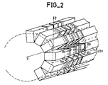
- FIG. 2 shows how the problem of the oblique size of the magnetic blocks of FIG. 1 can be solved in another way.
- the magnetic blocks have a trapezoidal section.
- the distances of the small bases and the large bases of the trapezoids to the z axis of the cylinder contribute to determining, with the value of the nominal magnetization, the value of the induction B0.
- the trapezoidal sections have been replaced by rectangular sections, one side of which is equal to the small base of the trapezoids.
- Blocks 100 and 190 to 220 respectively replace blocks 10 and 19 to 22 of Figures 1a and 1b. However if you are using non-parallelepipedic blocks you should execute the oblique cut before the magnetization.
- Figures 3 to 6 show the different steps of a general method of constructing a magnet according to the invention.
- One of the first problem to be solved consists in having to magnetize the blocks with a magnetization whose module can be adjusted.
- FIG. 3 indicates that this result is simply obtained by attaching plates (one could also put bars) made of magnetic materials 23 to plates 24 made of non-magnetic materials.
- plates one could also put bars
- the macroscopically equivalent magnetization of a block thus constituted is equal to the product of the intrinsic magnetization of the parts made of magnetic materials by the proportion (e1 / (e1 + e2)) of these magnetic materials in the set .
- the brick thus formed is of standard size. It is calculated to be able to be magnetized in a standard magnetizer such as the magnetizer 28 of FIG. 4.
- the current I which flows through this magnetizer must be sufficiently strong, and produce a sufficiently strong excitation, so that all the parts in magnetizable materials of the brick are brought to their magnetization saturation. If we call M s this magnetization of saturation, the brick will be magnetized with a value macroscopically equal to the product of M s by the proportion of magnetic material.
- the magnetic bricks are then assembled to form the magnetic blocks described so far.
- the blocks comprise, juxtaposed to each other, bricks magnetized orthogonally to each other.
- a block 29 in FIG. 5 comprises bricks of radial magnetization 30 to 32 juxtaposed, or even stacked, with bricks 33 to 35 of tangential magnetization.
- the assembly of the bricks in the blocks can be carried out in the same way as the assembly of the plates or pavers in the bricks: that is to say with adhesives based on epoxy resin.
- the formed blocks are then placed on a crown 36 made of epoxy resin. If they are rectangular they are separated from each other by wedges such as 37 in the form of a wedge.
- the crowns are housed ( Figure 6) in cradles such as 38 on which they can rest by all their lower parts.
- the cradles 38 and the crowns 36 are provided with means for ensuring a slight rotation or a slight offset, in one direction or the other, at the crowns.
- a threaded rod 39 resting on the cradle 38 can be screwed into a pomelle 40 secured to the crown and cause the rotation of this crown when the rod is turned. In this way, there is a simple means of industrially correcting the homogeneity of the constructed magnet on the site.
- a field is homogeneous to an order h if all the polynomial terms of power less than or equal to h have a zero coefficient.
- the number of sections n a should be such that: not at greater than or equal to (h + 1) / 2.
- the number of blocks per section n b it must be such that: not b greater than or equal to (h + 3).
- the optimization recommended by the invention proposes a minimal structure, that is to say one in which the number of blocks to be produced ultimately is as small as possible in order to obtain homogeneity at a given order.
- the number of blocks to be manipulated is low which facilitates manufacture and adjustment of the magnet.
- the manufacture of blocks and crowns is relatively easy, the installation and adjustment of these crowns is delicate.
- a number of blocks can be installed greater than what is necessary.
- the most practical industrial solution is such that the number of blocks per section is greater than or equal to twice the number of sections plus one.
- the solution which leads to the largest lateral technical openings in the case of a non-variegated structure is that where the blocks are the largest and where their number is therefore minimal.
- the magnetic materials used are either ferrites, Strontium or Barium, or alloys of Samarium - Cobalt, or alloys of Iron-Neodymium-Boron. These different materials have intrinsic remanent magnetizations with different saturation. They are also of density and different prices. We can choose in this way, according to the different specifications of induction field to produce, which is the most suitable solution.
- the principle of calculating the interior and exterior radii of the annular sections as well as the heights of these sections is the same in the case of the invention as that which leads to the determination of the blocks in the state of the art cited. It is noted, however, that at constant interior and exterior radii regardless of the section, the thicknesses of these sections along the axis must increase as one moves away from the center of the area of interest of the magnet. This appears in particular in Figures 1 and 2.
Landscapes
- Physics & Mathematics (AREA)
- Electromagnetism (AREA)
- Engineering & Computer Science (AREA)
- Power Engineering (AREA)
- Condensed Matter Physics & Semiconductors (AREA)
- General Physics & Mathematics (AREA)
- Magnetic Resonance Imaging Apparatus (AREA)
Claims (11)
- Zylindrischer Permanentmagnet (1) zur Erzeugung eines gleichförmigen und transversalen (X) Magnetfeldes (B₀) mit eine Permanentmagnetisierung aufweisenden magnetisierten Blöcken (7-18), die entlang des Zylinders in rinqförmige Abschnitte (2-6) aufgeteilt sind, die entlang des Zylinders angeordnet und gleichmäßig über den Umfang des jeweiligen Abschnitts verteilt sind, wobei die Magnetisierung in den Blöcken zumindest teilweise in dem jeweiligen Block bezüglich des Zylinders tangential orientiert ist, dadurch gekennzeichnet, daß die Blöcke Bausteine (30-32) mit radialer Magnetisierung und Bausteine (33-35) mit tangentialer Magnetisierung umfassen.
- Magnet nach Anspruch 1, dadurch gekennzeichnet, daß die Magnetisierung gleichermaßen teilweise radial ist und daß der Modul dieser radialen Magnetisierung von einem Block zum anderen entsprechend dem Cosinus des Markierungswinkels (φ) variiert, der zwischen der Richtung des querverlaufenden Feldes und dem Azimut dieses Blockes liegt.
- Magnet gemäß Anspruch 1, dadurch gekennzeichnet, daß die Magnetisierung zumindest teilweise tangential ist und daß der Modul dieser tangentialen Magnetisierung von Block zu Block entsprechend dem Sinus des Markierungswinkels (φ) variiert, der zwischen der Richtung des querverlaufenden Feldes und dem Azimut dieses Blockes liegt.
- Magnet nach einem der Ansprüche 1 bis 3, dadurch gekennzeichent, daß in jedem Block die Bausteine mit radialer Magnetisierung und die Bausteine mit tangentialer Magnetisierung in gleichem Verhältnis vorgesehen sind, um einen Magneten mit einem bipolaren Moment Null zu bilden.
- Magnet nach Anspruch 4, dadurch gekennzeichnet, daß die Anzahl der Blöcke pro Abschnitt nb größer oder gleich der doppelten Anzahl der Abschnitte na plus eins ist.
- Magnet nach Anspruch 5, dadurch gekennzeichnet, daß nb gleich 2 (na + 1) (Fig. 1-2) ist.
- Magnet nach Anspruch 4, dadurch gekennzeichnet, daß na 5 beträgt, daß nb 12 beträgt und daß das Feld gleichförmig ist bei der Ordnung 9.
- Magnet nach einem der Ansprüche 1 bis 3, dadurch gekennzeichnet, daß die Blöcke auf beweglichen (39, 40) Kronen (36) angebracht sind, um die Homogenität des Magneten zu korrigieren.
- Zylindrischer Permanentmagnet zur Erzeugung eines gleichförmigen und transversalen Magnetfeldes mit eine Permanentmagnetisierung aufweisenden magnetisierten Blöcken, die in eine Anzahl na von ringförmigen Abschnitten aufgeteilt sind, die entlang des Zylinders angeordnet und über den Umfang eines jeden Abschnittes in einer Anzahl nb von Blöcken verteilt sind, dadurch gekennzeichnet, daß nb größer oder gleich 2(na+1) ist.
- Magnet nach Anspruch 9, dadurch gekennzeichnet, daß er bei einer Ordnung h homogen ist, wenn na größer als (h + 1)/2 ist und wenn nb größer als (h + 3) ist.
- Magnet nach einem der Ansprüche 1 bis 10, dadurch gekennzeichnet, daß die Stärke der ringförmigen Abschnitte parallel zur Zylinderachse gemessen mit der Entfernung von der Mitte des Magneten zunimmt.
Applications Claiming Priority (2)
| Application Number | Priority Date | Filing Date | Title |
|---|---|---|---|
| FR8614417A FR2605450B1 (fr) | 1986-10-17 | 1986-10-17 | Aimant permanent cylindrique pour produire un champ d'induction uniforme et transverse |
| FR8614417 | 1986-10-17 |
Publications (2)
| Publication Number | Publication Date |
|---|---|
| EP0328537A1 EP0328537A1 (de) | 1989-08-23 |
| EP0328537B1 true EP0328537B1 (de) | 1993-01-20 |
Family
ID=9339927
Family Applications (1)
| Application Number | Title | Priority Date | Filing Date |
|---|---|---|---|
| EP87906826A Expired - Lifetime EP0328537B1 (de) | 1986-10-17 | 1987-10-13 | Zylindrischer permanentmagnet zur erzeugung eines homogenen, transversalen magnetfeldes |
Country Status (6)
| Country | Link |
|---|---|
| US (1) | US4999600A (de) |
| EP (1) | EP0328537B1 (de) |
| JP (1) | JPH02501004A (de) |
| DE (1) | DE3783774T2 (de) |
| FR (1) | FR2605450B1 (de) |
| WO (1) | WO1988002923A1 (de) |
Families Citing this family (27)
| Publication number | Priority date | Publication date | Assignee | Title |
|---|---|---|---|---|
| IT8921079A0 (it) * | 1989-07-03 | 1989-07-03 | Comec Srl | Sistema per la fabbricazione di magneti permanenti senza giochi, generatori di campo magnetico uniforme e relativi magneti permanenti elementari o compositi. |
| US4994777A (en) * | 1989-11-14 | 1991-02-19 | The United States Of America As Represented By The Secretary Of The Army | Enhanced magnetic field within enclosed cylindrical cavity |
| US5095271A (en) * | 1990-05-14 | 1992-03-10 | General Atomics | Compact open NMR systems for in situ measurement of moisture, salinity, and hydrocarbons |
| FR2665297B1 (fr) * | 1990-07-30 | 1992-10-09 | Centre Nat Rech Scient | Aimant permanent pour installation d'imagerie par resonance magnetique nucleaire. |
| US5216401A (en) * | 1992-06-02 | 1993-06-01 | The United States Of America As Represented By The Secretary Of The Army | Magnetic field sources having non-distorting access ports |
| WO1994002951A1 (en) * | 1992-07-27 | 1994-02-03 | New York University | High field magnets for medical applications |
| US5428333A (en) * | 1993-01-22 | 1995-06-27 | New York University | Method and apparatus for compensation of field distortion in a magnetic structure |
| US5396209A (en) * | 1994-02-16 | 1995-03-07 | The United States Of America As Represented By The Secretary Of The Army | Light-weight magnetic field sources having distortion-free access ports |
| US5523731A (en) * | 1995-04-12 | 1996-06-04 | The United States Of America As Represented By The Secretary Of The Army | Simplified method of making light-weight magnetic field sources having distortion-free access ports |
| GB2425842A (en) * | 2005-05-05 | 2006-11-08 | Plant Bioscience Ltd | Magnetic resonance sensor with rotatable magnetic rods placed around the sample |
| US7498915B1 (en) * | 2005-11-18 | 2009-03-03 | The United States Of America As Represented By The Secretary Of The Army | Application of superconductive permanent magnets |
| CN100370558C (zh) * | 2006-02-16 | 2008-02-20 | 北京航空航天大学 | 磁场沿磁体轴向方向均匀分布的渐变磁体 |
| WO2007120057A1 (en) * | 2006-04-18 | 2007-10-25 | Victoria Link Limited | Magnetic field-generating apparatus |
| EP2195815B1 (de) * | 2007-10-04 | 2016-12-07 | Hussmann Corporation | Permanentmagneteinrichtung |
| US8179220B2 (en) * | 2008-05-28 | 2012-05-15 | Otto Voegeli | Confined field magnet system and method |
| US8209988B2 (en) * | 2008-09-24 | 2012-07-03 | Husssmann Corporation | Magnetic refrigeration device |
| CH701267B1 (fr) * | 2009-06-02 | 2014-08-29 | Clean Cooling Systems Sa | Générateur de champ magnétique et dispositif magnétocalorique comportant ledit générateur de champ magnétique. |
| FR2949601A1 (fr) * | 2009-08-28 | 2011-03-04 | Commissariat Energie Atomique | Dispositif d'aimant permanent cylindrique a champ magnetique induit d'orientation predeterminee et procede de fabrication |
| FR2949604B1 (fr) | 2009-08-28 | 2012-03-02 | Commissariat Energie Atomique | Structure aimantee axisymetrique induisant en son centre un champ homogene d'orientation predeterminee |
| US9659706B2 (en) * | 2011-09-22 | 2017-05-23 | The Trustees Of Dartmouth College | Methods for making radially anisotropic thin-film magnetic torroidal cores |
| JP5989415B2 (ja) * | 2012-06-20 | 2016-09-07 | 信越化学工業株式会社 | 筒状磁気回路の組立方法 |
| CN103048176A (zh) * | 2012-12-13 | 2013-04-17 | 宁波大学 | 适用于化学实验室的磁性复合微粒悬浊液离析装置 |
| US10845441B1 (en) * | 2017-10-17 | 2020-11-24 | Nuevomr, Llc | Continuously adjustable passive shims for magnets |
| EP3489972B1 (de) * | 2017-11-27 | 2020-04-15 | Premo, S.A. | Induktorvorrichtung mit leichtgewichtiger konfiguration |
| EP3808457A1 (de) * | 2019-10-16 | 2021-04-21 | Chin-Ming Hsieh | Magnetisierungsvorrichtung |
| US11961664B2 (en) | 2020-07-31 | 2024-04-16 | Fermi Research Alliance, Llc | High temperature superconducting magnet |
| CN112594963B (zh) * | 2020-12-31 | 2024-08-23 | 包头稀土研究院 | 室温磁制冷机用圆柱型阵列式磁体及其装配方法 |
Family Cites Families (13)
| Publication number | Priority date | Publication date | Assignee | Title |
|---|---|---|---|---|
| NL66942C (de) * | 1900-01-01 | |||
| GB447409A (en) * | 1934-11-13 | 1936-05-13 | Cleopatra Leonita Eugenie Olga | Improvements in cutting devices particularly for opening milk and like cartons |
| NL133615C (de) * | 1962-10-04 | |||
| US4538130A (en) * | 1984-04-23 | 1985-08-27 | Field Effects, Inc. | Tunable segmented ring magnet and method of manufacture |
| JPS61102544A (ja) * | 1984-10-25 | 1986-05-21 | Sumitomo Special Metals Co Ltd | 磁界発生装置 |
| JPS61218110A (ja) * | 1985-03-23 | 1986-09-27 | キヤノン株式会社 | 発熱抵抗体 |
| US4614930A (en) * | 1985-03-25 | 1986-09-30 | General Electric Company | Radially magnetized cylindrical magnet |
| US4703276A (en) * | 1985-04-24 | 1987-10-27 | Elscint Ltd. | Permanent magnet ring assembly for NMR imaging system and method for using such assembly |
| DE3518852A1 (de) * | 1985-05-23 | 1986-11-27 | Siemens AG, 1000 Berlin und 8000 München | Magnet eines kernspintomographen |
| US4707663A (en) * | 1985-08-15 | 1987-11-17 | Fonar Corporation | Nuclear magnetic resonance apparatus using low energy magnetic elements |
| US4658228A (en) * | 1986-05-01 | 1987-04-14 | The United States Of America As Represented By The Secreatry Of The Army | Confinement of longitudinal, axially symmetric, magnetic fields to annular regions with permanent magnets |
| US4692732A (en) * | 1986-05-30 | 1987-09-08 | The United States Of America As Represented By The Secretary Of The Army | Remanence varying in a leakage free permanent magnet field source |
| US4701737A (en) * | 1986-05-30 | 1987-10-20 | The United States Of America As Represented By The Secretary Of The Army | Leakage-free, linearly varying axial permanent magnet field source |
-
1986
- 1986-10-17 FR FR8614417A patent/FR2605450B1/fr not_active Expired
-
1987
- 1987-10-13 US US07/353,674 patent/US4999600A/en not_active Expired - Fee Related
- 1987-10-13 EP EP87906826A patent/EP0328537B1/de not_active Expired - Lifetime
- 1987-10-13 JP JP62506178A patent/JPH02501004A/ja active Pending
- 1987-10-13 DE DE8787906826T patent/DE3783774T2/de not_active Expired - Fee Related
- 1987-10-13 WO PCT/FR1987/000392 patent/WO1988002923A1/fr not_active Ceased
Also Published As
| Publication number | Publication date |
|---|---|
| DE3783774D1 (de) | 1993-03-04 |
| FR2605450A1 (fr) | 1988-04-22 |
| JPH02501004A (ja) | 1990-04-05 |
| WO1988002923A1 (fr) | 1988-04-21 |
| DE3783774T2 (de) | 1993-05-13 |
| FR2605450B1 (fr) | 1988-12-02 |
| EP0328537A1 (de) | 1989-08-23 |
| US4999600A (en) | 1991-03-12 |
Similar Documents
| Publication | Publication Date | Title |
|---|---|---|
| EP0328537B1 (de) | Zylindrischer permanentmagnet zur erzeugung eines homogenen, transversalen magnetfeldes | |
| EP0329666A1 (de) | Sphärischer permanentmagnet mit äquatorialem zutritt | |
| EP0326572B1 (de) | Zylindrischer permanentmagnet mit longitudinalem induktionsfeld | |
| EP0346333B1 (de) | Vorrichtung zur korrektur von magnetfeldinhomogenitäten eines magneten mit hilfe von magnetischen elementen | |
| EP2470923B1 (de) | Magnetisierte struktur zur induktion eines homogenen feldes in der mitte mit vordefinierter ausrichtung | |
| EP2470921B1 (de) | Zylinderförmige permanentmagnetvorrichtung zur erzeugung eines gesteuerten magnetfelds in einem bestimmten abstand von ihrer oberfläche | |
| EP2568482B1 (de) | Erzeuger eines homogenes Magnetfelds | |
| EP0221810A1 (de) | Gradientenspule | |
| EP0178216B1 (de) | Erzeugung von Zusatzfeldern durch Spulensysteme zur Erhaltung von Polarisationsfeldern mit konstanten Gradienten in einem Magnet mit Polarisationspolarelementen für die NMR-Abbildung | |
| EP0393092B1 (de) | Vorrichtung zur bilderzeugung mittels magnetischer kernresonanz, verfahren zur korrektur der inhomogenität und fabrikationsverfahren von in der vorrichtung angewendeten magneten | |
| EP2593806B1 (de) | Permanentmagnetvorrichtung zur erzeugung eines einheitlichen versetzten magnetfelds | |
| EP0623939A1 (de) | Davermagnetstruktur zur Herstellung einer stabilen und homogenen magnetischen Induktion in einem bestimmten Raum | |
| WO2011023910A1 (fr) | Dispositif d'aimant permanent cylindrique a champ magnetique induit d'orientation predeterminee et procede de fabrication | |
| EP1969384B1 (de) | Verfahren und einrichtung zum erzeugen eines homogenen magnetfelds in einem interessierenden bereich, insbesondere für nmr-bildgebung | |
| EP0225814A1 (de) | Gradientenspule für NMR-Abbildungsanordnungen | |
| EP1952171B1 (de) | Nmr-maschine mit in röhren eingebauten elektromagnetischen gradientenspulen | |
| EP0275767A1 (de) | In einem Punkt zentriertes dreiachsiges Magnetometer | |
| WO2015044554A1 (fr) | Systeme d'antenne radiofrequence fonde sur l'hybridation de mode pour dispositif de resonance magnetique nucleaire |
Legal Events
| Date | Code | Title | Description |
|---|---|---|---|
| PUAI | Public reference made under article 153(3) epc to a published international application that has entered the european phase |
Free format text: ORIGINAL CODE: 0009012 |
|
| 17P | Request for examination filed |
Effective date: 19890407 |
|
| AK | Designated contracting states |
Kind code of ref document: A1 Designated state(s): DE GB IT NL |
|
| 17Q | First examination report despatched |
Effective date: 19910418 |
|
| GRAA | (expected) grant |
Free format text: ORIGINAL CODE: 0009210 |
|
| AK | Designated contracting states |
Kind code of ref document: B1 Designated state(s): DE GB IT NL |
|
| PG25 | Lapsed in a contracting state [announced via postgrant information from national office to epo] |
Ref country code: IT Free format text: LAPSE BECAUSE OF FAILURE TO SUBMIT A TRANSLATION OF THE DESCRIPTION OR TO PAY THE FEE WITHIN THE PRE;WARNING: LAPSES OF ITALIAN PATENTS WITH EFFECTIVE DATE BEFORE 2007 MAY HAVE OCCURRED AT ANY TIME BEFORE 2007. THE CORRECT EFFECTIVE DATE MAY BE DIFFERENT FROM THE ONE RECORDED.SCRIBED TIME-LIMIT Effective date: 19930120 |
|
| GBT | Gb: translation of ep patent filed (gb section 77(6)(a)/1977) |
Effective date: 19930202 |
|
| REF | Corresponds to: |
Ref document number: 3783774 Country of ref document: DE Date of ref document: 19930304 |
|
| PLBE | No opposition filed within time limit |
Free format text: ORIGINAL CODE: 0009261 |
|
| STAA | Information on the status of an ep patent application or granted ep patent |
Free format text: STATUS: NO OPPOSITION FILED WITHIN TIME LIMIT |
|
| 26N | No opposition filed | ||
| PGFP | Annual fee paid to national office [announced via postgrant information from national office to epo] |
Ref country code: GB Payment date: 19950918 Year of fee payment: 9 |
|
| PGFP | Annual fee paid to national office [announced via postgrant information from national office to epo] |
Ref country code: DE Payment date: 19950920 Year of fee payment: 9 |
|
| PGFP | Annual fee paid to national office [announced via postgrant information from national office to epo] |
Ref country code: NL Payment date: 19950927 Year of fee payment: 9 |
|
| PG25 | Lapsed in a contracting state [announced via postgrant information from national office to epo] |
Ref country code: GB Effective date: 19961013 |
|
| PG25 | Lapsed in a contracting state [announced via postgrant information from national office to epo] |
Ref country code: NL Effective date: 19970501 |
|
| GBPC | Gb: european patent ceased through non-payment of renewal fee |
Effective date: 19961013 |
|
| NLV4 | Nl: lapsed or anulled due to non-payment of the annual fee |
Effective date: 19970501 |
|
| PG25 | Lapsed in a contracting state [announced via postgrant information from national office to epo] |
Ref country code: DE Effective date: 19970701 |