EP0328716A1 - Soudeuse - Google Patents
Soudeuse Download PDFInfo
- Publication number
- EP0328716A1 EP0328716A1 EP88102483A EP88102483A EP0328716A1 EP 0328716 A1 EP0328716 A1 EP 0328716A1 EP 88102483 A EP88102483 A EP 88102483A EP 88102483 A EP88102483 A EP 88102483A EP 0328716 A1 EP0328716 A1 EP 0328716A1
- Authority
- EP
- European Patent Office
- Prior art keywords
- electrode
- contact
- carrier material
- welding device
- electrodes
- Prior art date
- Legal status (The legal status is an assumption and is not a legal conclusion. Google has not performed a legal analysis and makes no representation as to the accuracy of the status listed.)
- Granted
Links
- 238000005476 soldering Methods 0.000 title 1
- 239000012876 carrier material Substances 0.000 claims abstract description 40
- 238000003466 welding Methods 0.000 claims abstract description 40
- 230000000284 resting effect Effects 0.000 claims abstract 2
- 230000001360 synchronised effect Effects 0.000 claims abstract 2
- 239000000463 material Substances 0.000 claims description 19
- 108090000623 proteins and genes Proteins 0.000 claims 1
- 238000011161 development Methods 0.000 description 1
- 230000018109 developmental process Effects 0.000 description 1
- 238000006073 displacement reaction Methods 0.000 description 1
- 230000007257 malfunction Effects 0.000 description 1
- 238000004519 manufacturing process Methods 0.000 description 1
Images

Classifications
-
- H—ELECTRICITY
- H01—ELECTRIC ELEMENTS
- H01H—ELECTRIC SWITCHES; RELAYS; SELECTORS; EMERGENCY PROTECTIVE DEVICES
- H01H11/00—Apparatus or processes specially adapted for the manufacture of electric switches
- H01H11/04—Apparatus or processes specially adapted for the manufacture of electric switches of switch contacts
- H01H11/041—Apparatus or processes specially adapted for the manufacture of electric switches of switch contacts by bonding of a contact marking face to a contact body portion
- H01H11/043—Apparatus or processes specially adapted for the manufacture of electric switches of switch contacts by bonding of a contact marking face to a contact body portion by resistance welding
-
- H—ELECTRICITY
- H01—ELECTRIC ELEMENTS
- H01R—ELECTRICALLY-CONDUCTIVE CONNECTIONS; STRUCTURAL ASSOCIATIONS OF A PLURALITY OF MUTUALLY-INSULATED ELECTRICAL CONNECTING ELEMENTS; COUPLING DEVICES; CURRENT COLLECTORS
- H01R43/00—Apparatus or processes specially adapted for manufacturing, assembling, maintaining, or repairing of line connectors or current collectors or for joining electric conductors
- H01R43/02—Apparatus or processes specially adapted for manufacturing, assembling, maintaining, or repairing of line connectors or current collectors or for joining electric conductors for soldered or welded connections
Definitions
- the invention relates to a welding device of the type mentioned in the preamble of claim 1.
- Such welding devices are used to manufacture high-quality contact parts for electrical and electronic components.
- the invention has for its object to provide a welding device of the type mentioned, which makes it possible without changing the position of the welding device to the running direction of the Trä germaterials to weld contact pieces at any angle to the carrier material.
- the contact piece can be rotated with the help of the rotatable electrode to any angular orientation with respect to the running direction of the carrier material.
- electrode inserts can be provided at the end of the electrodes, which have engaging parts, for example a recess for engaging with the individual contact pieces, so that they can be rotated to a clear position.
- both electrodes are slidably supported along their longitudinal axis, so that the electrode, which otherwise comes into engagement with a contact piece that has already been welded on, can be countersunk to contact pieces already welded onto the carrier material without letting damage happen.
- the feeder for the contact pieces may preferably include a gate valve which includes a first rod-shaped member driven by a control member, a second rod-shaped member engageable with an end of a contact member, and a driver member.
- the second rod-shaped part which comes into engagement with the end of a contact piece and introduces it between the carrier material and the one electrode, can have a very small cross section, which is less than or equal to the cross section of the contact pieces. Due to the essentially all-round encirclement of the rod-shaped parts and the driver piece, there is no danger of the second rod-shaped part buckling even if resistance is opposed to the movement.
- the contact pieces can be produced from a continuous wire-shaped contact material, which is optionally profiled.
- the welding device has a cutting device for cutting off the contact pieces from the contact material and this cutting device preferably consists of a knife rail covering a guide channel for the contact material and a cutting punch which can be brought into cutting engagement with the knife rail through the guide channel under the control of a control member is.
- this cutting device preferably consists of a knife rail covering a guide channel for the contact material and a cutting punch which can be brought into cutting engagement with the knife rail through the guide channel under the control of a control member is.
- the cutting punch can be reground without affecting the dimensional accuracy.
- the contact piece separated from the cutting punch can furthermore be transferred from the cutting punch into the movement path of the second rod-shaped part of the transport slide.
- the cutting punch can cooperate with a spring-loaded counterpart, which is located opposite it on the side of the knife rail and which holds the contact piece in firm contact on the surface of the cutting punch.
- the synchronization devices can preferably be formed by sets of cams, which bring about the movement of the individual parts of the welding device via control elements.
- two separate sets of cams are provided which are driven synchronously with one another, one cam being provided for driving an electrode. This results in a variety of control options for the electrodes and the other parts of the welding device.
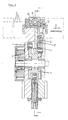
- the embodiment of the welding device shown in the drawings has a multi-part housing with the parts 1, 2, 3, 4, the parts 1, 2 forming an upper housing, while the parts 3, 4 form a lower housing.
- respective cam plate sets 5 and 6 are arranged in the upper housing 1, 2 and the lower housing 3, 4, respectively, which control the movement sequence of the welding device.
- Both sets of cams are connected to one another via a belt or chain drive 41 according to FIG. 2 and rotate synchronously with one another.
- the contact material 52 is moved according to FIG. 1 with the aid of a feed carriage 7 and a clamping piece 8 into a guide channel formed between the housings.
- the clamping piece 8 is pressed against the contact material 52 with the aid of a spring-loaded slide 9, so that this contact material is drawn in in the direction of the arrow in a continuously adjustable length becomes.
- a lever 10 which is driven by a cam disk of the cam disk set 6 about a pivot point 12 against the action of a spring 11, can execute an idle travel designated "X" in a recess in the feed slide 7 without the feed slide 7 moving.
- a spring-loaded slide 9 is first relieved of a lug on the lever 10 and clamps the contact material via the clamping piece 8.
- a retaining clamp lever 13 is lifted off the contact material via a cam track located on the lever 10.
- the lever 10 engages with the feed carriage 7 and moves it and thus the contact material 52 in the direction of the arrow.
- this feed device can be driven from a single cam disc with the aid of a single control element, for example a roller arranged on the lever 10.
- a cutting plunger 16 which is adjustably mounted in a slide 15, is moved through the guide channel for the contact material 52 against a knife rail 17 via a further cam disk of the cam disk set 6 and a lever 14 forming a control member, the part in the part of the Section of the contact material located in the guide channel is separated therefrom to form a contact piece, the length of which corresponds to the longitudinal extent of the cutting punch 16 in the longitudinal direction of the guide channel for the contact material 52.
- Both the knife bar 17 and the cutting punch 16 can be easily reground without impairing their dimensional accuracy.
- the contact piece When the contact piece is disconnected, it is lifted by the cutting punch into the movement path of a transport slide with the parts 19 to 21, which will be explained in more detail.
- the contact piece is held in contact with the cutting punch 16 with the aid of a counterpart 18, which is acted upon by a spring, this counterpart 18 having its own precisely defined stop. Regardless of a possible regrinding of the cutting punch 16, the cut contact piece thus always reaches an exact position in the path of movement of the transport slide.
- This transport slide is driven via a cam disk of the cam disk set 5 arranged in the upper housing part 1, 2 with the aid of a lever arm 25, this lever arm 25 being the control member forms for the transport slide and is biased against a spring-loaded slide 24 against the corresponding cam.
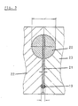
- the transport slide consists of a first rod-shaped part 20, a driver piece 21 and a second rod-shaped part 19, as can be seen in particular from FIG. 3.
- the parts of the transport slide 19 to 21 are essentially completely enclosed by a guide 22, 23 and the position of the rod-shaped part 19 with respect to the carrier material 50 according to FIG. 1 determines whether the contact pieces are welded above or below this carrier material.
- the transport slide is designed in three parts in order to be able to form the rod-shaped part 19 that comes into engagement with the cut contact piece with the smallest possible cross-section, so that, especially with micro-profile contact pieces, these contact pieces are not guided in the guides 22, 23 by the size of the transport slide in Question is asked.
- the rod-shaped part 20 which engages with the lever 25, on the other hand, is of larger dimensions and has a slot for the engagement of the lever 25.
- This design of the transport slide has the advantage that it cannot buckle even in the event of any malfunctions by the guides 22, 23 and, furthermore, the rod-shaped part 19 can be replaced without any significant effort.
- this transport slide enables the contact to be transported in the manner already indicated pieces 51 under the carrier material 50 and over the lower electrode 30, if desired.
- the lower electrode 30 can also be rotated about its longitudinal axis 26a.
- the rotatability of the upper electrode 26 makes it possible to rotate the contact piece inserted between the electrode 26 and the carrier material 50 by the transport slide 19 to 21 with respect to the transport direction of the carrier material 50.
- the electrode 26 with an electrode insert 27 via a separate cam disc in the cam disc set 5 with the aid of a spring-loaded lever 28 is lowered so far over the carrier material that the contact piece has space with a few hundredths of a millimeter of play, but is nevertheless optimally guided.
- the electrode insert 27 can be provided with engagement devices, for example a depression, the shape of which roughly corresponds to the cross-sectional shape of the contact piece.
- the lower electrode 30 is also with its electrode insert 31 Movable in the direction of the longitudinal axis 26a via a separate cam disk in the cam disk set 6, a spring-loaded lever 26 and a positioning spring 33. This electrode can thus also be placed on the underside of the carrier material 50.
- the adjusting spring 33 is several times stronger than the welding force spring 29 at the rear end of the electrode 26. If the contact pieces are to be welded onto the carrier material 50 from below, the adjusting spring 33 can be replaced by a corresponding welding force spring.
- the contact piece 51 has been inserted between the electrode 26 and the carrier material 50 in the manner described, the electrode 26 with the electrode insert 27 is completely lowered, the lever 28 is released from a fine adjustment screw 34 and the welding force is generated exclusively via the welding force spring 29. At this time, a welding pulse is given over appropriate welding power cables connected to the electrodes 26,30.
- the contact section is to be welded at a predetermined angle between zero and 90 degrees to the direction of travel of the carrier material 50, then before the electrode 26 is finally lowered, it is moved together with the electrode insert 27 via a separate cam disc in the Cam set 5, a slide 36, an adjustable rack 37 and a fixed to the electrode 26, but isolated from this pinion 38, as can be seen in particular in Fig. 2, so that the electrode insert 27, the contact piece in the predetermined position turns before the welding force spring comes into effect.
- the electrode 26 with the electrode insert 27 first lifts off over the separate cam disk in the cam disk set 5, whereupon the electrode 26 is turned back into its starting position.
- the slide 36 is acted upon by a lever 39 which engages in it but is only partially shown in FIG. 2 by a spring in the direction of the cam disk.
- the lower electrode 30 with the electrode insert 31 is also lifted off the carrier material with the aid of a lever 32 via a corresponding cam disk in the cam disk set 6 in the lower housing 3, 4.
- both electrodes 26, 30 are supported in roller guides 40 in order to achieve easy displacement along their longitudinal axes 26a.
- the described rotatability of the at least one electrode 26 makes it possible to arrange the contact pieces at any angle to the direction of passage of the carrier material, which is perpendicular to the plane of the drawing in FIG. 1, the longitudinal direction the contact pieces can even run parallel to this direction of passage.
- both electrodes 26,30 Due to the longitudinal mobility of both electrodes 26,30, it is also possible to provide the carrier material with contact pieces on both sides without the risk of damaging these contact pieces when welding the contact pieces provided on the opposite side of the carrier material.
- Both electrodes are still insulated from dimensions and they can be designed to be coolable, if necessary.
Landscapes
- Engineering & Computer Science (AREA)
- Manufacturing & Machinery (AREA)
- Resistance Welding (AREA)
Applications Claiming Priority (1)
| Application Number | Priority Date | Filing Date | Title |
|---|---|---|---|
| DE3703686A DE3703686C1 (de) | 1987-02-06 | 1987-02-06 | Schweissvorrichtung |
Publications (2)
| Publication Number | Publication Date |
|---|---|
| EP0328716A1 true EP0328716A1 (fr) | 1989-08-23 |
| EP0328716B1 EP0328716B1 (fr) | 1991-10-16 |
Family
ID=6320416
Family Applications (1)
| Application Number | Title | Priority Date | Filing Date |
|---|---|---|---|
| EP88102483A Expired - Lifetime EP0328716B1 (fr) | 1987-02-06 | 1988-02-19 | Soudeuse |
Country Status (3)
| Country | Link |
|---|---|
| US (1) | US4894507A (fr) |
| EP (1) | EP0328716B1 (fr) |
| DE (1) | DE3703686C1 (fr) |
Cited By (2)
| Publication number | Priority date | Publication date | Assignee | Title |
|---|---|---|---|---|
| CN100561625C (zh) * | 2008-02-08 | 2009-11-18 | 桂林市森工机械技术开发有限公司 | 生产三复合电触头铆钉的设备 |
| CN101752116B (zh) * | 2009-12-30 | 2011-12-21 | 温州聚星银触点有限公司 | 三层复合电触点的制造设备 |
Families Citing this family (6)
| Publication number | Priority date | Publication date | Assignee | Title |
|---|---|---|---|---|
| DE3822150A1 (de) * | 1988-06-30 | 1990-01-04 | Finzer Saeckinger Maschinen Fa | Schweissaggregat zum schweissen eines vereinzelten kontaktelementes auf ein traegerelement |
| US5115111A (en) * | 1990-08-06 | 1992-05-19 | Hughes Aircraft Company | Dual tip rotating welding electrode |
| DE19529981C2 (de) * | 1995-04-20 | 2000-12-28 | Duerrwaechter E Dr Doduco | Vorrichtung für das Aufschweißen von elektrischen Kontaktstücken durch Widerstandsschweißen |
| DE19528273C1 (de) * | 1995-04-24 | 1997-03-27 | Duerrwaechter E Dr Doduco | Schweißwerkzeug für das Aufschweißen von elektrischen Kontaktstücken durch Widerstandsschweißen |
| DE19528272C1 (de) * | 1995-04-24 | 1996-07-04 | Duerrwaechter E Dr Doduco | Schweißwerkzeug für das Aufschweißen von elektrischen Kontaktstücken durch Widerstandsschweißen |
| JP5570318B2 (ja) * | 2010-06-23 | 2014-08-13 | Obara Group株式会社 | 溶接機のイコライズ装置 |
Citations (4)
| Publication number | Priority date | Publication date | Assignee | Title |
|---|---|---|---|---|
| US2307579A (en) * | 1940-07-09 | 1943-01-05 | Gen Electric | Method of attaching strip contact material to switch members |
| CH325187A (fr) * | 1953-04-07 | 1957-10-31 | Western Electric Co | Machine automatique pour souder des contacts sur des conducteurs d'une pièce de relais électrique |
| FR2364736A1 (fr) * | 1976-09-18 | 1978-04-14 | Heraeus Gmbh W C | Machine a souder par contacts |
| FR2538285A1 (fr) * | 1982-12-22 | 1984-06-29 | Finzer Kg Heinz | Unite de soudage pour la fixation par soudure de contacts, de preference profiles, sur un support |
Family Cites Families (2)
| Publication number | Priority date | Publication date | Assignee | Title |
|---|---|---|---|---|
| AT379973B (de) * | 1984-01-13 | 1986-03-25 | Evg Entwicklung Verwert Ges | Nach der elektrischen widerstandsmethode arbeitende gitterschweissmaschine |
| US4724294A (en) * | 1985-10-15 | 1988-02-09 | D-M Automation | Programmable welder |
-
1987
- 1987-02-06 DE DE3703686A patent/DE3703686C1/de not_active Expired
-
1988
- 1988-02-19 EP EP88102483A patent/EP0328716B1/fr not_active Expired - Lifetime
- 1988-05-04 US US07/190,006 patent/US4894507A/en not_active Expired - Fee Related
Patent Citations (4)
| Publication number | Priority date | Publication date | Assignee | Title |
|---|---|---|---|---|
| US2307579A (en) * | 1940-07-09 | 1943-01-05 | Gen Electric | Method of attaching strip contact material to switch members |
| CH325187A (fr) * | 1953-04-07 | 1957-10-31 | Western Electric Co | Machine automatique pour souder des contacts sur des conducteurs d'une pièce de relais électrique |
| FR2364736A1 (fr) * | 1976-09-18 | 1978-04-14 | Heraeus Gmbh W C | Machine a souder par contacts |
| FR2538285A1 (fr) * | 1982-12-22 | 1984-06-29 | Finzer Kg Heinz | Unite de soudage pour la fixation par soudure de contacts, de preference profiles, sur un support |
Non-Patent Citations (1)
| Title |
|---|
| WELDING JOURNAL * |
Cited By (2)
| Publication number | Priority date | Publication date | Assignee | Title |
|---|---|---|---|---|
| CN100561625C (zh) * | 2008-02-08 | 2009-11-18 | 桂林市森工机械技术开发有限公司 | 生产三复合电触头铆钉的设备 |
| CN101752116B (zh) * | 2009-12-30 | 2011-12-21 | 温州聚星银触点有限公司 | 三层复合电触点的制造设备 |
Also Published As
| Publication number | Publication date |
|---|---|
| US4894507A (en) | 1990-01-16 |
| DE3703686C1 (de) | 1988-05-05 |
| EP0328716B1 (fr) | 1991-10-16 |
Similar Documents
| Publication | Publication Date | Title |
|---|---|---|
| DE2704540C2 (fr) | ||
| DE3872512T2 (de) | Kantenbearbeitungsmaschine. | |
| DE3836023C2 (de) | Einstellvorrichtung für eine Blattführung | |
| DE2356140C2 (de) | Vorrichtung zur Befestigung von wenigstens einem zuvor auf einem dünnen Plastikfilm montierten integrierten Schaltungsplättchen | |
| EP1353420B1 (fr) | Dispositif de sertissage | |
| DE3307463A1 (de) | Plattenpositioniervorrichtung | |
| DE2118909A1 (de) | Vorrichtung zum blattweisen Zuführen von Blättern | |
| DE69407111T2 (de) | Nibbelwerkzeug | |
| DE2741576A1 (de) | Bearbeitungsmaschine fuer draht und band, insbesondere stanz- und biegeautomat, mit mehreren werkzeugebenen | |
| DE2747164A1 (de) | Vorrichtung zur handhabung elektrischer bauteile | |
| DE69401444T2 (de) | Vorrichtung zum automatischen Einstellen eines Becherförderers gemäss der Grösse der zu fördernden Gegenstände, und Förderer zur Ausübung des Verfahrens | |
| EP3563959A1 (fr) | Dispositif de sciage | |
| DE2024821B2 (de) | Vorrichtung zum Anschließen von elektrischen AnschluBteilen an die Flachleiter eines isolierten Flachbandkabels | |
| DE3220814C2 (de) | Vorrichtung zum Ausrichten eines mit Randlochungen für Bindelemente versehenen Blattstapels | |
| EP0328716B1 (fr) | Soudeuse | |
| DE3731863C2 (fr) | ||
| EP0163849B1 (fr) | Dispositif de transport pour un automate de confection de câble | |
| DE3223086C2 (fr) | ||
| DE3440523C2 (de) | Schneidvorrichtung zum Schneiden von gestapeltem Flachmaterial | |
| DE19532130C2 (de) | Vorrichtung und Verfahren zum Herstellen eines Kabelbaums | |
| DE2259921C2 (de) | Maschine zum Abtrennen der Anschlußklemmen von einem Trägerstreifen | |
| DE3138912A1 (de) | Speckentschwartungs- und enthaeutungsmaschine | |
| DE3586837T2 (de) | Vorrichtung zum zusammensetzen von zweiteiligen steckerverbindern. | |
| CH624326A5 (fr) | ||
| DE2308341C2 (de) | Maschine zum Abtrennen der Anschlußklemmen von einem Trägerstreifen und deren Einsetzen in eine Schaltungsplatte |
Legal Events
| Date | Code | Title | Description |
|---|---|---|---|
| PUAI | Public reference made under article 153(3) epc to a published international application that has entered the european phase |
Free format text: ORIGINAL CODE: 0009012 |
|
| AK | Designated contracting states |
Kind code of ref document: A1 Designated state(s): CH FR GB IT LI |
|
| 17P | Request for examination filed |
Effective date: 19890905 |
|
| 17Q | First examination report despatched |
Effective date: 19910117 |
|
| GRAA | (expected) grant |
Free format text: ORIGINAL CODE: 0009210 |
|
| AK | Designated contracting states |
Kind code of ref document: B1 Designated state(s): CH FR GB IT LI |
|
| ITF | It: translation for a ep patent filed | ||
| ET | Fr: translation filed | ||
| GBT | Gb: translation of ep patent filed (gb section 77(6)(a)/1977) | ||
| PLBE | No opposition filed within time limit |
Free format text: ORIGINAL CODE: 0009261 |
|
| STAA | Information on the status of an ep patent application or granted ep patent |
Free format text: STATUS: NO OPPOSITION FILED WITHIN TIME LIMIT |
|
| 26N | No opposition filed | ||
| PGFP | Annual fee paid to national office [announced via postgrant information from national office to epo] |
Ref country code: FR Payment date: 19960124 Year of fee payment: 9 |
|
| PG25 | Lapsed in a contracting state [announced via postgrant information from national office to epo] |
Ref country code: FR Effective date: 19971030 |
|
| REG | Reference to a national code |
Ref country code: CH Ref legal event code: PUE Owner name: HORST THODE TRANSFER- ALOIS CAMENZIND |
|
| REG | Reference to a national code |
Ref country code: FR Ref legal event code: ST |
|
| PGFP | Annual fee paid to national office [announced via postgrant information from national office to epo] |
Ref country code: GB Payment date: 19990215 Year of fee payment: 12 |
|
| PGFP | Annual fee paid to national office [announced via postgrant information from national office to epo] |
Ref country code: CH Payment date: 19990517 Year of fee payment: 12 |
|
| PG25 | Lapsed in a contracting state [announced via postgrant information from national office to epo] |
Ref country code: GB Free format text: LAPSE BECAUSE OF NON-PAYMENT OF DUE FEES Effective date: 20000219 |
|
| PG25 | Lapsed in a contracting state [announced via postgrant information from national office to epo] |
Ref country code: LI Free format text: LAPSE BECAUSE OF NON-PAYMENT OF DUE FEES Effective date: 20000229 Ref country code: CH Free format text: LAPSE BECAUSE OF NON-PAYMENT OF DUE FEES Effective date: 20000229 |
|
| GBPC | Gb: european patent ceased through non-payment of renewal fee |
Effective date: 20000219 |
|
| REG | Reference to a national code |
Ref country code: CH Ref legal event code: PL |
|
| PG25 | Lapsed in a contracting state [announced via postgrant information from national office to epo] |
Ref country code: IT Free format text: LAPSE BECAUSE OF NON-PAYMENT OF DUE FEES;WARNING: LAPSES OF ITALIAN PATENTS WITH EFFECTIVE DATE BEFORE 2007 MAY HAVE OCCURRED AT ANY TIME BEFORE 2007. THE CORRECT EFFECTIVE DATE MAY BE DIFFERENT FROM THE ONE RECORDED. Effective date: 20050219 |