EP0328730A2 - Système de mesure inertielle de la vitesse ou de l'accélération et circuit de traitement du signal pour un tel système - Google Patents
Système de mesure inertielle de la vitesse ou de l'accélération et circuit de traitement du signal pour un tel système Download PDFInfo
- Publication number
- EP0328730A2 EP0328730A2 EP88114659A EP88114659A EP0328730A2 EP 0328730 A2 EP0328730 A2 EP 0328730A2 EP 88114659 A EP88114659 A EP 88114659A EP 88114659 A EP88114659 A EP 88114659A EP 0328730 A2 EP0328730 A2 EP 0328730A2
- Authority
- EP
- European Patent Office
- Prior art keywords
- analog
- signal processing
- multiplier
- converter
- circuit
- Prior art date
- Legal status (The legal status is an assumption and is not a legal conclusion. Google has not performed a legal analysis and makes no representation as to the accuracy of the status listed.)
- Withdrawn
Links
- 238000005259 measurement Methods 0.000 title claims abstract description 10
- 230000001133 acceleration Effects 0.000 title claims abstract description 7
- 239000013078 crystal Substances 0.000 claims description 3
- 239000010453 quartz Substances 0.000 claims description 3
- VYPSYNLAJGMNEJ-UHFFFAOYSA-N silicon dioxide Inorganic materials O=[Si]=O VYPSYNLAJGMNEJ-UHFFFAOYSA-N 0.000 claims description 3
- 230000003750 conditioning effect Effects 0.000 claims description 2
- 238000006243 chemical reaction Methods 0.000 abstract description 5
- 230000010354 integration Effects 0.000 description 9
- 230000006978 adaptation Effects 0.000 description 5
- 239000003990 capacitor Substances 0.000 description 3
- 238000010586 diagram Methods 0.000 description 3
- 238000009825 accumulation Methods 0.000 description 2
- 230000003044 adaptive effect Effects 0.000 description 1
- 230000003321 amplification Effects 0.000 description 1
- 230000000903 blocking effect Effects 0.000 description 1
- 230000001939 inductive effect Effects 0.000 description 1
- 230000007774 longterm Effects 0.000 description 1
- 238000000034 method Methods 0.000 description 1
- 238000003199 nucleic acid amplification method Methods 0.000 description 1
- 230000002093 peripheral effect Effects 0.000 description 1
- 230000036962 time dependent Effects 0.000 description 1
Images


Classifications
-
- G—PHYSICS
- G01—MEASURING; TESTING
- G01P—MEASURING LINEAR OR ANGULAR SPEED, ACCELERATION, DECELERATION, OR SHOCK; INDICATING PRESENCE, ABSENCE, OR DIRECTION, OF MOVEMENT
- G01P7/00—Measuring speed by integrating acceleration
Definitions
- the invention relates to a device for inertial speed or acceleration measurement according to the preamble of patent claim 1.
- Inertial systems for speed or acceleration measurement mostly gyroscopes (seismic mass) were used as sensors or sensors, which require an angle measurement and an integration of the measurement signals.
- ABS anti-lock braking system
- ASR anti-slip control (inductive or photoelectric sensors).
- An analog circuit is usually used for signal processing, in which a capacitor is charged, the charging voltage of which is proportional to the integral of the charging current.
- the charging current tolerance, the drift and offset of the amplifier and capacitor go directly into the accuracy of the integration. i.e. they have a negative impact on this.
- the resolution is determined by difficulties that arise when processing small signals.
- the object of the invention is to eliminate the possible sources of error in a circuit for analog signal preparation and processing in inertial measuring systems.
- the direct parallel processing of the signals provided according to the invention avoids high computer complexity - with a processor and the necessary peripherals.
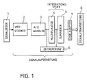
- Signal transmitters 1 transmit measured values detected by sensors, such as speed 'v', acceleration 'g', as electrical signals to a signal processing circuit.
- the signals present at the input are initially preamplified in amplifier 2 and converter 3.
- the signals, which are now in digital form, are then fed to an integration stage consisting of multiplier 4 and summer 5.
- a time reference 6 is connected to the links 3, 4 and 5 of the block as a further encoder, which is fed by a clock generator.
- the factors X and Y are processed into a product P in the multiplier and summer.
- the result P of a multiplication is added to the result P of the subsequent multiplication (register accumulation).
- the signal conditioning then ends with a code adaptation in element 7 for a subsequent further signal processing / use in element 8.
- the clock generator 9 feeds the time reference 6.
- the input from the signal generator 1 is designed analogously for an input voltage U e and connected to an analog operational amplifier 2 (for 100-fold amplification).
- the A / D converter 3 can process, for example, 12-bit wide numbers.
- a low-byte zero positioner or zero position indicator 10 can advantageously be connected to it.
- the links 2 and 10 together form a comparison aid.
- the A / D converter 3 is connected to the multiplier / summer 4/5.
- An integration factor can be supplied to this by a further transmitter 11.
- a signed inverter can also be connected. If the product sum overflows Message by link 12.
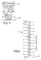
- a signal output at 15 can also be analog, for example in the form of a voltage U a , which is generated (converted back) by a (12 bit) D / A converter 14.
- a frequency or clock generator 9 is equipped with a quartz crystal 16, which serves as a timer.
- Link 9 is a frequency divider 17 and this is connected to a start input of the A / D converter 3.
- the operational amplifier 2 is connected to the analog input 18 and this serves as a comparison aid with the zero indicator 10, the latter having a light-emitting diode LED 19 for the purpose of indicating the zero position (cf. FIG. 4).
- An LED can also serve as an operating display.
- both the time reference 6 and the A / D converter 3 with its matching aids 2 and 10 as well as an integration factor generator 11 and a reset unit 20 are connected to the multiplier / totalizer 4/5.
- the reset unit serves among other things resetting to switching on and also blocking or releasing signals to the intended outputs: analog, in FIG. 5 and digitally via code adaptation 7 to further processing 8, in FIG. 6.
- the input signal X (angular velocity) from the sensor is generated in an A / D converter with a width of 12 bits.
- the constancy of the reference voltage is important for the conversion accuracy in converter 3.
- the Accuracy of the drive frequency, which is generated with a quartz and subsequent division, is of secondary importance.
- the other influences that could affect the accuracy of an analog circuit are eliminated in the subsequent digital integration.
- the analog signal converted to 12 bits is present at the multiplication module 4 in the 'offset binary code' in order to achieve the polarity change necessary for integration.
- the clock generator 9 forms a crystal of 3.2768 MHz drive frequency. In the divider 9 the frequency is divided down to 800 Hz. This controls both the A / D converter and the multiplication module. The time step for the integration is therefore 1.25 ms.
- An operational amplifier OP is used to balance the analog signal voltage source.
- An 8-fold OR gate with a downstream LED 3 facilitates zero adjustment of the D / A converter.
- the 27 outputs of the product register P are loaded with pull-down resistors, which specify the value 0 when the block is reset.
- the lower 12 bits of the product register are suppressed for scaling reasons.
- the output signal is formed by the following 12 bits, which means a resolution of +/- 2048 steps.
- This output range which corresponds to an angle in the present case, can be varied as desired by appropriately scaling the value Y or the frequency divider. Since both the factor Y and the frequency divider can be entered as binary values, the integration can be adapted as a function of other input signals. This is important for adaptive control systems.
- the 12 gates at element 7 are used to selectively adapt the signal code to subsequent circuits / further processing 8: positive / negative logic, offset / true binary BCD.
- Various components of the circuit diagram serve to control and monitor the integrator, such as resetting, zeroing, switching on / off and overflow control. If the integrated digital angle signal is to be further processed in an analog manner, it can be implemented with a suitable D / A converter with the following OP amplifier stage. In the present case, this was done here - but for measurement purposes.
Landscapes
- Physics & Mathematics (AREA)
- General Physics & Mathematics (AREA)
- Analogue/Digital Conversion (AREA)
- Control Of Transmission Device (AREA)
Applications Claiming Priority (2)
| Application Number | Priority Date | Filing Date | Title |
|---|---|---|---|
| DE3803872 | 1988-02-09 | ||
| DE3803872A DE3803872A1 (de) | 1988-02-09 | 1988-02-09 | Einrichtung zur inertialen geschwindigkeits- oder beschleunigungsmessung und schaltungsanordnung zur signalaufbereitung und -verarbeitung hierfuer |
Publications (2)
| Publication Number | Publication Date |
|---|---|
| EP0328730A2 true EP0328730A2 (fr) | 1989-08-23 |
| EP0328730A3 EP0328730A3 (fr) | 1990-12-19 |
Family
ID=6346960
Family Applications (1)
| Application Number | Title | Priority Date | Filing Date |
|---|---|---|---|
| EP19880114659 Withdrawn EP0328730A3 (fr) | 1988-02-09 | 1988-09-08 | Système de mesure inertielle de la vitesse ou de l'accélération et circuit de traitement du signal pour un tel système |
Country Status (3)
| Country | Link |
|---|---|
| US (1) | US4978956A (fr) |
| EP (1) | EP0328730A3 (fr) |
| DE (1) | DE3803872A1 (fr) |
Cited By (2)
| Publication number | Priority date | Publication date | Assignee | Title |
|---|---|---|---|---|
| EP0838660A1 (fr) * | 1996-10-25 | 1998-04-29 | Murata Manufacturing Co., Ltd. | Appareil de calcul d'une vitesse |
| US6028495A (en) * | 1996-10-11 | 2000-02-22 | Murata Manufacturing Co., Ltd. | Magnetostatic-wave device |
Families Citing this family (4)
| Publication number | Priority date | Publication date | Assignee | Title |
|---|---|---|---|---|
| US5113189A (en) * | 1991-06-21 | 1992-05-12 | Motorola, Inc. | Frequency translating coherent analog to digital conversion system for modulated signals |
| RU2183011C1 (ru) * | 2001-03-23 | 2002-05-27 | ЗАО "Нефтегазкомплектсервис" | Способ навигационного обследования трубопроводов (варианты) |
| DE102004007486A1 (de) * | 2004-02-13 | 2005-10-27 | Micronas Gmbh | Sensor mit Multiplex-Datenausgang |
| US8866662B1 (en) * | 2012-10-21 | 2014-10-21 | Steve Naumov | Sequential analog/digital conversion and multiplication |
Family Cites Families (9)
| Publication number | Priority date | Publication date | Assignee | Title |
|---|---|---|---|---|
| DE2056997A1 (de) * | 1970-11-20 | 1972-05-25 | Bodenseewerk Geraetetech | Einrichtung zum selbsttätigen Ausrichten einer kreiselstabilisierten Trägheitsplattform |
| USRE30298E (en) * | 1974-07-22 | 1980-06-03 | Impact sensing detector | |
| US4254406A (en) * | 1977-07-29 | 1981-03-03 | Mcdonnell Douglas Corporation | Integrating analog-to-digital converter |
| US4282470A (en) * | 1979-04-30 | 1981-08-04 | Northrop Corporation | Close loop control apparatus and method for a force rebalance transducer |
| JPS5873231A (ja) * | 1981-10-27 | 1983-05-02 | Shimadzu Corp | Ad変換装置 |
| DE3304203A1 (de) * | 1983-02-08 | 1984-08-09 | Bayer Ag, 5090 Leverkusen | Substituierte oximether |
| US4522062A (en) * | 1983-09-02 | 1985-06-11 | Sundstrand Data Control, Inc. | Digital processor for use with an accelerometer based angular rate sensor |
| US4683456A (en) * | 1983-12-28 | 1987-07-28 | Timeback Systems, Inc. | Methods and apparatus for analog to digital conversion |
| IL75470A0 (en) * | 1984-06-20 | 1985-10-31 | Sundstrand Data Control | Digital output instrument |
-
1988
- 1988-02-09 DE DE3803872A patent/DE3803872A1/de not_active Withdrawn
- 1988-09-08 EP EP19880114659 patent/EP0328730A3/fr not_active Withdrawn
-
1989
- 1989-02-03 US US07/306,403 patent/US4978956A/en not_active Expired - Fee Related
Cited By (2)
| Publication number | Priority date | Publication date | Assignee | Title |
|---|---|---|---|---|
| US6028495A (en) * | 1996-10-11 | 2000-02-22 | Murata Manufacturing Co., Ltd. | Magnetostatic-wave device |
| EP0838660A1 (fr) * | 1996-10-25 | 1998-04-29 | Murata Manufacturing Co., Ltd. | Appareil de calcul d'une vitesse |
Also Published As
| Publication number | Publication date |
|---|---|
| EP0328730A3 (fr) | 1990-12-19 |
| DE3803872A1 (de) | 1989-08-17 |
| US4978956A (en) | 1990-12-18 |
Similar Documents
| Publication | Publication Date | Title |
|---|---|---|
| DE2429278A1 (de) | Elektronischer drehmomentschluessel | |
| DE3037888C2 (fr) | ||
| EP0328730A2 (fr) | Système de mesure inertielle de la vitesse ou de l'accélération et circuit de traitement du signal pour un tel système | |
| EP0356438B1 (fr) | Procede et dispositif pour evaluer une grandeur electrique analogique | |
| CH434776A (de) | Einrichtung zum Messen von Längen mittels Impulszählung | |
| DE2341322A1 (de) | Anordnung zum erzeugen eines messausgangssignales, dessen hoehe linear von der groesse eines zu messenden widerstandes abhaengt | |
| DE2148775A1 (de) | Messeinrichtung mit kapazitivem abgriff | |
| EP0753756A2 (fr) | Circuit et procédé pour mesurer la différence de capacité entre deux capacités | |
| EP0066681B1 (fr) | Procédé pour mesurer une quantité correspondant au rapport cyclique d'un signal électrique périodique rectangulaire et procédé pour mesurer l'angle de phase entre deux signaux électriques périodiques rectangulaires en quadrature et dispositifs pour l'application desdits procédés | |
| EP0514634A1 (fr) | Procédé de correction des erreurs de mesure | |
| EP0280261A2 (fr) | Circuit pour la production d'un signal carré indépendant de la température à une grandeur mesurée | |
| DE3710871A1 (de) | Schaltung zur formung einer messsignalspannung in ein rechtecksignal | |
| EP0137896B1 (fr) | Circuit pour compenser les variations du facteur de transfert d'une sonde linéaire de champ magnétique | |
| EP0221402B1 (fr) | Convertisseur de grandeur analogique en fréquence | |
| DE2952311A1 (de) | Verfahren und vorrichtung zum umsetzen einer messspannung in einen digitalen wert | |
| DE68908740T2 (de) | Versorgungsschaltung für eine Hallsonden-Multiplizierungsschaltung. | |
| DE3314261C2 (de) | Analog-digital-wandler-anordnung und -verfahren | |
| DE102018110100B4 (de) | Galvanisch getrennte, symmetrische Sensorversorgung eines Analog-Digital-Wandlers für asymmetrische Versorgung | |
| DE3311831A1 (de) | Tiefpass fuer eine elektronische waage | |
| DE3639559A1 (de) | Einrichtung zur messung physikalischer groessen | |
| DE2352049B2 (de) | Anordnung zur selbsttaetigen nullpunkt-korrektur von analog-digital-umsetzern | |
| DE2346307B1 (de) | Elektrische Schaltungsanordnung zur linearen Umwandlung messgroessenabhaengiger Kapazitaetsaenderungen | |
| DE2337579A1 (de) | Messgeraet | |
| DE2154415C3 (de) | Spannungsfrequenzumsetzer | |
| DE1205206B (de) | Schaltungsanordnung zur Messung des Kehr-wertes der Periode eines Kernreaktors |
Legal Events
| Date | Code | Title | Description |
|---|---|---|---|
| PUAI | Public reference made under article 153(3) epc to a published international application that has entered the european phase |
Free format text: ORIGINAL CODE: 0009012 |
|
| AK | Designated contracting states |
Kind code of ref document: A2 Designated state(s): DE FR GB SE |
|
| PUAL | Search report despatched |
Free format text: ORIGINAL CODE: 0009013 |
|
| AK | Designated contracting states |
Kind code of ref document: A3 Designated state(s): DE FR GB SE |
|
| STAA | Information on the status of an ep patent application or granted ep patent |
Free format text: STATUS: THE APPLICATION HAS BEEN WITHDRAWN |
|
| 18W | Application withdrawn |
Withdrawal date: 19910326 |