EP0328992A2 - Fiche de connexion électrique - Google Patents
Fiche de connexion électrique Download PDFInfo
- Publication number
- EP0328992A2 EP0328992A2 EP89102073A EP89102073A EP0328992A2 EP 0328992 A2 EP0328992 A2 EP 0328992A2 EP 89102073 A EP89102073 A EP 89102073A EP 89102073 A EP89102073 A EP 89102073A EP 0328992 A2 EP0328992 A2 EP 0328992A2
- Authority
- EP
- European Patent Office
- Prior art keywords
- crimp sleeve
- cone
- connector
- crimp
- plug
- Prior art date
- Legal status (The legal status is an assumption and is not a legal conclusion. Google has not performed a legal analysis and makes no representation as to the accuracy of the status listed.)
- Withdrawn
Links
- 238000003780 insertion Methods 0.000 abstract description 25
- 230000037431 insertion Effects 0.000 abstract description 25
- 238000000034 method Methods 0.000 abstract description 2
- RYGMFSIKBFXOCR-UHFFFAOYSA-N Copper Chemical compound [Cu] RYGMFSIKBFXOCR-UHFFFAOYSA-N 0.000 description 2
- 239000004020 conductor Substances 0.000 description 2
- 239000000463 material Substances 0.000 description 2
- 150000001875 compounds Chemical class 0.000 description 1
- 229910052802 copper Inorganic materials 0.000 description 1
- 239000010949 copper Substances 0.000 description 1
- 238000002788 crimping Methods 0.000 description 1
- 230000034994 death Effects 0.000 description 1
- 231100000517 death Toxicity 0.000 description 1
- 238000006073 displacement reaction Methods 0.000 description 1
- 238000004519 manufacturing process Methods 0.000 description 1
- 230000000149 penetrating effect Effects 0.000 description 1
Images
Classifications
-
- H—ELECTRICITY
- H01—ELECTRIC ELEMENTS
- H01R—ELECTRICALLY-CONDUCTIVE CONNECTIONS; STRUCTURAL ASSOCIATIONS OF A PLURALITY OF MUTUALLY-INSULATED ELECTRICAL CONNECTING ELEMENTS; COUPLING DEVICES; CURRENT COLLECTORS
- H01R4/00—Electrically-conductive connections between two or more conductive members in direct contact, i.e. touching one another; Means for effecting or maintaining such contact; Electrically-conductive connections having two or more spaced connecting locations for conductors and using contact members penetrating insulation
- H01R4/10—Electrically-conductive connections between two or more conductive members in direct contact, i.e. touching one another; Means for effecting or maintaining such contact; Electrically-conductive connections having two or more spaced connecting locations for conductors and using contact members penetrating insulation effected solely by twisting, wrapping, bending, crimping, or other permanent deformation
- H01R4/18—Electrically-conductive connections between two or more conductive members in direct contact, i.e. touching one another; Means for effecting or maintaining such contact; Electrically-conductive connections having two or more spaced connecting locations for conductors and using contact members penetrating insulation effected solely by twisting, wrapping, bending, crimping, or other permanent deformation by crimping
- H01R4/20—Electrically-conductive connections between two or more conductive members in direct contact, i.e. touching one another; Means for effecting or maintaining such contact; Electrically-conductive connections having two or more spaced connecting locations for conductors and using contact members penetrating insulation effected solely by twisting, wrapping, bending, crimping, or other permanent deformation by crimping using a crimping sleeve
-
- H—ELECTRICITY
- H01—ELECTRIC ELEMENTS
- H01R—ELECTRICALLY-CONDUCTIVE CONNECTIONS; STRUCTURAL ASSOCIATIONS OF A PLURALITY OF MUTUALLY-INSULATED ELECTRICAL CONNECTING ELEMENTS; COUPLING DEVICES; CURRENT COLLECTORS
- H01R43/00—Apparatus or processes specially adapted for manufacturing, assembling, maintaining, or repairing of line connectors or current collectors or for joining electric conductors
- H01R43/04—Apparatus or processes specially adapted for manufacturing, assembling, maintaining, or repairing of line connectors or current collectors or for joining electric conductors for forming connections by deformation, e.g. crimping tool
Definitions
- the invention relates to an electrical connector with a contact pins and a grounding spring-holding plug bridge, which is inextricably molded with a handle body after connecting the wires of a supplied electrical line, the plug bridge having two lateral holding blocks for holding and guiding the grounding spring encompassing it and the grounding spring with a crimp sleeve is connected, which is arranged next to one of the support frames.
- Such electrical connectors as shown for example in DE-GM 69 95 96, are required in very large numbers.
- the connector pins of these connectors generally have a longitudinal bore at the end for receiving the wires of the line Consisting of copper braid. After inserting the copper wire, the longitudinal holes are then crimped so that a secure connection is given. The same applies to the earth contact, which is formed by an earth spring.
- DE-GM 85 11 857 makes it easier to insert the ends of the strands, which shows insertion openings in the connector pins, which are provided with a small embossed funnel at the insertion mouth.
- this funnel-shaped insertion opening is so short and the funnel wall is inclined so steeply to the insertion direction that the danger described above is by no means eliminated.
- the object of the invention is to enable the automatic insertion of strands consisting of many individual wires into the crimp sleeve of the grounding spring.
- This is achieved according to the invention in that the bracket located on the connector bridge is made in one piece with one over the crimp sleeve is connected to the crossbar that extends out of the grounding spring and has a conical recess that is open to the outside and coaxial with the crimp sleeve.
- the recess is double-cone-shaped according to the invention, so that the crimp sleeve can engage in the cone adjacent to it.
- the crimp sleeve of this earthing spring reaches the area of the cone adjacent to the connector bridge and is centered and held by this cone.
- this crimp sleeve which is now fixed in a clear position, is the cone on the other side, which serves as an insertion funnel for the end of the strand, that is to say when the individual wires of this strand are inserted securely into this crimp sleeve.
- the crossbar has not only the advantage that it places the crimp sleeve of the earth spring in a clear position relative to the insertion openings of the plug pin te brings, but that now this crimp sleeve is fixed in its position.
- the conical recess adjacent to the crimp sleeve can of course be dispensed with.
- the diameter of the constriction between the two cones should be slightly smaller than the inside diameter of the crimp sleeve.
- the crimp sleeve is made of a material that is relatively strong compared to the strand, it is advisable to shape the cone in which the crimp sleeve engages shorter and with a steeper flank angle than the cone on the other side, which serves as an insertion funnel for the strand ends.
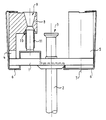
- Plug pins (2) are formed in a plug bridge (1) and protrude beyond them with their insertion openings (3) over the plug bridge (1). Molded onto the connector bridge (1) are two retaining brackets (4, 5) that hold and guide an earthing spring (6). One bracket (5) can also have an earthing contact sleeve, as indicated by dash-dotted lines (7).
- a crossbar (8) with a double-cone-shaped recess (9, 10) is formed on the support bracket (4).
- a crimp sleeve (11) of the earthing spring (6) reaches the area of the cone (10), as a result of which it is centered and held.
- the stranded ends can now be inserted into this pre-assembled connector.
- the strands to be inserted into the crimp sleeve (11) of the grounding contact (6) it should be noted that the strands can be securely inserted into the crimp sleeve (11) and crimped there through the cone (9), which serves here as an insertion funnel.
- the position of this crimp sleeve (11) is now fixed, so that there is no longer any fear of displacement of the crimp sleeve due to the high pressure of the plastic compound to be molded around this connector.
Landscapes
- Details Of Connecting Devices For Male And Female Coupling (AREA)
- Coupling Device And Connection With Printed Circuit (AREA)
Applications Claiming Priority (2)
| Application Number | Priority Date | Filing Date | Title |
|---|---|---|---|
| DE8802047U DE8802047U1 (de) | 1988-02-17 | 1988-02-17 | Elektrischer Steckkontakt |
| DE8802047U | 1988-02-17 |
Publications (2)
| Publication Number | Publication Date |
|---|---|
| EP0328992A2 true EP0328992A2 (fr) | 1989-08-23 |
| EP0328992A3 EP0328992A3 (fr) | 1991-08-21 |
Family
ID=6820769
Family Applications (1)
| Application Number | Title | Priority Date | Filing Date |
|---|---|---|---|
| EP19890102073 Withdrawn EP0328992A3 (fr) | 1988-02-17 | 1989-02-07 | Fiche de connexion électrique |
Country Status (2)
| Country | Link |
|---|---|
| EP (1) | EP0328992A3 (fr) |
| DE (1) | DE8802047U1 (fr) |
Cited By (4)
| Publication number | Priority date | Publication date | Assignee | Title |
|---|---|---|---|---|
| EP0391298B1 (fr) * | 1989-04-07 | 1994-08-24 | Taller GmbH | Connecteur à contact de protection et à une aide d'entrée coordonnée à une douille de raccordement pour le contact de protection |
| EP0773606A3 (fr) * | 1995-11-10 | 1998-05-27 | Taller GmbH | Fiche a contact de protection avec une aide d'entree sur la douille de raccordement du conducteur de protection |
| CN101515687B (zh) * | 2008-02-19 | 2010-12-29 | 建通精密工业股份有限公司 | 具有接地弹片的三极电源插头内架 |
| GB2526933A (en) * | 2014-05-15 | 2015-12-09 | Thomas Waible | Plug insert for a power plug |
Families Citing this family (2)
| Publication number | Priority date | Publication date | Assignee | Title |
|---|---|---|---|---|
| DE3807717A1 (de) * | 1988-03-09 | 1989-09-28 | Taller Gmbh | Elektrischer geraetestecker mit einer halteplatte fuer die kontaktfedern |
| DE8817241U1 (de) * | 1988-03-09 | 1995-05-11 | Taller Gmbh, 76337 Waldbronn | Schutzkontaktstecker mit Steckerbrücke und hohlzylindrischen Anschlußstiften für die Stromleiter und den Schutzleiter |
Family Cites Families (5)
| Publication number | Priority date | Publication date | Assignee | Title |
|---|---|---|---|---|
| DE1108767B (de) * | 1957-05-02 | 1961-06-15 | Busch Jaeger Duerener Metall | Elektrischer Stecker |
| DE2532872C3 (de) * | 1975-07-23 | 1979-11-15 | Kabelwerke Reinshagen Gmbh, 5600 Wuppertal | Elektrische Steckvorrichtung und Verfahren zu ihrer Herstellung |
| DE3202747C3 (de) * | 1982-01-28 | 1995-03-23 | Krups Fa Robert | Netzstecker |
| FR2538625A1 (fr) * | 1982-12-23 | 1984-06-29 | Cemrep | Fiche a broches pour prise de courant electrique |
| DE8716567U1 (de) * | 1987-12-16 | 1988-02-11 | Schaar, Ingrid, 7517 Waldbronn | Steckerstift |
-
1988
- 1988-02-17 DE DE8802047U patent/DE8802047U1/de not_active Expired
-
1989
- 1989-02-07 EP EP19890102073 patent/EP0328992A3/fr not_active Withdrawn
Cited By (6)
| Publication number | Priority date | Publication date | Assignee | Title |
|---|---|---|---|---|
| EP0391298B1 (fr) * | 1989-04-07 | 1994-08-24 | Taller GmbH | Connecteur à contact de protection et à une aide d'entrée coordonnée à une douille de raccordement pour le contact de protection |
| EP0773606A3 (fr) * | 1995-11-10 | 1998-05-27 | Taller GmbH | Fiche a contact de protection avec une aide d'entree sur la douille de raccordement du conducteur de protection |
| EP0918375A1 (fr) * | 1995-11-10 | 1999-05-26 | Taller GmbH | Insert pour un connecteur à contact de protection et à une aide d'entrée coordonneé à une douille de raccordement pour le contact de protection |
| CN101515687B (zh) * | 2008-02-19 | 2010-12-29 | 建通精密工业股份有限公司 | 具有接地弹片的三极电源插头内架 |
| GB2526933A (en) * | 2014-05-15 | 2015-12-09 | Thomas Waible | Plug insert for a power plug |
| GB2526933B (en) * | 2014-05-15 | 2017-12-27 | Waible Thomas | Plug insert for a power plug |
Also Published As
| Publication number | Publication date |
|---|---|
| EP0328992A3 (fr) | 1991-08-21 |
| DE8802047U1 (de) | 1988-03-31 |
Similar Documents
| Publication | Publication Date | Title |
|---|---|---|
| DE10140910C2 (de) | Elektrischer Steckverbinder | |
| DE102009021594A1 (de) | Elektrischer Steckverbinder und elektrische Steckverbindung | |
| DE3915852C2 (de) | Gespritzter Schutzkontaktstecker mit den Anschlußbuchsen für die Strom- und den Schutzleiter zugeordneten Einführhilfen | |
| EP0163116B1 (fr) | Fiche multiple | |
| DE202008004892U1 (de) | Schirmübergabeelement für Steckverbinder | |
| DE3202747C3 (de) | Netzstecker | |
| DE4108886C1 (en) | Sensor e.g. proximity switch, IR transceiver - has line connection terminals of plug contacts designed as limbs of bifurcation | |
| DE8716567U1 (de) | Steckerstift | |
| EP0328992A2 (fr) | Fiche de connexion électrique | |
| DE3807716C3 (de) | Steckerbrücke für einen Schutzkontaktstecker mit hohlzylindrischen Anschlußstiften für die Stromleiter und den Schutzleiter | |
| DE4239261C2 (de) | Steckerbrücke für einen elektrischen Gerätestecker mit einem Paar von Stromleiterstiften (Kontaktstiften) und gegebenenfalls einem Schutzleiterstift (Erdstiift) | |
| DE3940652C2 (de) | Elektrische Steckverbindung | |
| DE3809772C1 (en) | Electrical plug connector | |
| EP0332035B1 (fr) | Fiche pour appareil électrique, avec une plaque d'ancrage pour les lames de contact | |
| EP0945929A2 (fr) | Connecteur pour un câble blindé | |
| DE3427361C1 (de) | Verbindung zwischen einem koaxialen Steckverbinder und einem Koaxialkabel | |
| DE3839011C2 (de) | Steckerbrücke für einen elektrischen Gerätestecker mit mindestens einem Phasen- und einem Nulleiterstift | |
| DE4012581C2 (de) | Schutzkontaktstecker mit einem brückenartigen Formteil | |
| DE10055148A1 (de) | Kabelanschluß- oder -verbindungseinrichtung | |
| EP0551068B1 (fr) | Prise de courant modulaire pour appareil électrique | |
| EP0452761B1 (fr) | Fiche à contact de protection avec une plaquette de base et contact de terre à ressort | |
| EP0773606B1 (fr) | Fiche a contact de protection avec une aide d'entree sur la douille de raccordement du conducteur de protection | |
| EP0521190A1 (fr) | Pont à fiches pour une fiche à contact de protection d'un appareil électrique | |
| DE4012582C2 (de) | Schutzkontaktstecker mit einem integrierten T-förmigen Formteil | |
| DE102004059162A1 (de) | Elektrisches Gerät mit einer Stromversorgungskupplung |
Legal Events
| Date | Code | Title | Description |
|---|---|---|---|
| PUAI | Public reference made under article 153(3) epc to a published international application that has entered the european phase |
Free format text: ORIGINAL CODE: 0009012 |
|
| AK | Designated contracting states |
Kind code of ref document: A2 Designated state(s): AT BE DE ES FR IT NL |
|
| PUAL | Search report despatched |
Free format text: ORIGINAL CODE: 0009013 |
|
| AK | Designated contracting states |
Kind code of ref document: A3 Designated state(s): AT BE DE ES FR IT NL |
|
| RAP1 | Party data changed (applicant data changed or rights of an application transferred) |
Owner name: SCHAAR, GERHARD |
|
| 17P | Request for examination filed |
Effective date: 19920416 |
|
| STAA | Information on the status of an ep patent application or granted ep patent |
Free format text: STATUS: THE APPLICATION IS DEEMED TO BE WITHDRAWN |
|
| 18D | Application deemed to be withdrawn |
Effective date: 19930901 |