EP0329045A2 - Dispositif de propulsion et de freinage pour automobile - Google Patents
Dispositif de propulsion et de freinage pour automobile Download PDFInfo
- Publication number
- EP0329045A2 EP0329045A2 EP89102393A EP89102393A EP0329045A2 EP 0329045 A2 EP0329045 A2 EP 0329045A2 EP 89102393 A EP89102393 A EP 89102393A EP 89102393 A EP89102393 A EP 89102393A EP 0329045 A2 EP0329045 A2 EP 0329045A2
- Authority
- EP
- European Patent Office
- Prior art keywords
- switch
- clutch
- drive
- switching
- connection
- Prior art date
- Legal status (The legal status is an assumption and is not a legal conclusion. Google has not performed a legal analysis and makes no representation as to the accuracy of the status listed.)
- Granted
Links
- 230000005540 biological transmission Effects 0.000 claims description 3
- 230000000994 depressogenic effect Effects 0.000 description 3
- 238000000034 method Methods 0.000 description 3
- 238000010586 diagram Methods 0.000 description 2
- 230000006735 deficit Effects 0.000 description 1
- 230000000881 depressing effect Effects 0.000 description 1
- 238000011161 development Methods 0.000 description 1
- 230000018109 developmental process Effects 0.000 description 1
- 230000000694 effects Effects 0.000 description 1
- 230000005284 excitation Effects 0.000 description 1
- 239000012530 fluid Substances 0.000 description 1
- 239000000446 fuel Substances 0.000 description 1
- 238000012986 modification Methods 0.000 description 1
- 230000004048 modification Effects 0.000 description 1
- 230000001960 triggered effect Effects 0.000 description 1
Images

Classifications
-
- B—PERFORMING OPERATIONS; TRANSPORTING
- B60—VEHICLES IN GENERAL
- B60T—VEHICLE BRAKE CONTROL SYSTEMS OR PARTS THEREOF; BRAKE CONTROL SYSTEMS OR PARTS THEREOF, IN GENERAL; ARRANGEMENT OF BRAKING ELEMENTS ON VEHICLES IN GENERAL; PORTABLE DEVICES FOR PREVENTING UNWANTED MOVEMENT OF VEHICLES; VEHICLE MODIFICATIONS TO FACILITATE COOLING OF BRAKES
- B60T8/00—Arrangements for adjusting wheel-braking force to meet varying vehicular or ground-surface conditions, e.g. limiting or varying distribution of braking force
- B60T8/32—Arrangements for adjusting wheel-braking force to meet varying vehicular or ground-surface conditions, e.g. limiting or varying distribution of braking force responsive to a speed condition, e.g. acceleration or deceleration
- B60T8/34—Arrangements for adjusting wheel-braking force to meet varying vehicular or ground-surface conditions, e.g. limiting or varying distribution of braking force responsive to a speed condition, e.g. acceleration or deceleration having a fluid pressure regulator responsive to a speed condition
- B60T8/343—Systems characterised by their lay-out
- B60T8/344—Hydraulic systems
- B60T8/346—2 Channel systems
-
- B—PERFORMING OPERATIONS; TRANSPORTING
- B60—VEHICLES IN GENERAL
- B60K—ARRANGEMENT OR MOUNTING OF PROPULSION UNITS OR OF TRANSMISSIONS IN VEHICLES; ARRANGEMENT OR MOUNTING OF PLURAL DIVERSE PRIME-MOVERS IN VEHICLES; AUXILIARY DRIVES FOR VEHICLES; INSTRUMENTATION OR DASHBOARDS FOR VEHICLES; ARRANGEMENTS IN CONNECTION WITH COOLING, AIR INTAKE, GAS EXHAUST OR FUEL SUPPLY OF PROPULSION UNITS IN VEHICLES
- B60K23/00—Arrangement or mounting of control devices for vehicle transmissions, or parts thereof, not otherwise provided for
- B60K23/08—Arrangement or mounting of control devices for vehicle transmissions, or parts thereof, not otherwise provided for for changing number of driven wheels, for switching from driving one axle to driving two or more axles
- B60K23/0808—Arrangement or mounting of control devices for vehicle transmissions, or parts thereof, not otherwise provided for for changing number of driven wheels, for switching from driving one axle to driving two or more axles for varying torque distribution between driven axles, e.g. by transfer clutch
-
- B—PERFORMING OPERATIONS; TRANSPORTING
- B60—VEHICLES IN GENERAL
- B60T—VEHICLE BRAKE CONTROL SYSTEMS OR PARTS THEREOF; BRAKE CONTROL SYSTEMS OR PARTS THEREOF, IN GENERAL; ARRANGEMENT OF BRAKING ELEMENTS ON VEHICLES IN GENERAL; PORTABLE DEVICES FOR PREVENTING UNWANTED MOVEMENT OF VEHICLES; VEHICLE MODIFICATIONS TO FACILITATE COOLING OF BRAKES
- B60T11/00—Transmitting braking action from initiating means to ultimate brake actuator without power assistance or drive or where such assistance or drive is irrelevant
- B60T11/10—Transmitting braking action from initiating means to ultimate brake actuator without power assistance or drive or where such assistance or drive is irrelevant transmitting by fluid means, e.g. hydraulic
- B60T11/103—Transmitting braking action from initiating means to ultimate brake actuator without power assistance or drive or where such assistance or drive is irrelevant transmitting by fluid means, e.g. hydraulic in combination with other control devices
-
- B—PERFORMING OPERATIONS; TRANSPORTING
- B60—VEHICLES IN GENERAL
- B60T—VEHICLE BRAKE CONTROL SYSTEMS OR PARTS THEREOF; BRAKE CONTROL SYSTEMS OR PARTS THEREOF, IN GENERAL; ARRANGEMENT OF BRAKING ELEMENTS ON VEHICLES IN GENERAL; PORTABLE DEVICES FOR PREVENTING UNWANTED MOVEMENT OF VEHICLES; VEHICLE MODIFICATIONS TO FACILITATE COOLING OF BRAKES
- B60T8/00—Arrangements for adjusting wheel-braking force to meet varying vehicular or ground-surface conditions, e.g. limiting or varying distribution of braking force
- B60T8/32—Arrangements for adjusting wheel-braking force to meet varying vehicular or ground-surface conditions, e.g. limiting or varying distribution of braking force responsive to a speed condition, e.g. acceleration or deceleration
- B60T8/321—Arrangements for adjusting wheel-braking force to meet varying vehicular or ground-surface conditions, e.g. limiting or varying distribution of braking force responsive to a speed condition, e.g. acceleration or deceleration deceleration
- B60T8/322—Systems specially adapted for vehicles driven by more than one axle, e.g. Four Wheel-Drive vehicles
-
- B—PERFORMING OPERATIONS; TRANSPORTING
- B60—VEHICLES IN GENERAL
- B60T—VEHICLE BRAKE CONTROL SYSTEMS OR PARTS THEREOF; BRAKE CONTROL SYSTEMS OR PARTS THEREOF, IN GENERAL; ARRANGEMENT OF BRAKING ELEMENTS ON VEHICLES IN GENERAL; PORTABLE DEVICES FOR PREVENTING UNWANTED MOVEMENT OF VEHICLES; VEHICLE MODIFICATIONS TO FACILITATE COOLING OF BRAKES
- B60T8/00—Arrangements for adjusting wheel-braking force to meet varying vehicular or ground-surface conditions, e.g. limiting or varying distribution of braking force
- B60T8/32—Arrangements for adjusting wheel-braking force to meet varying vehicular or ground-surface conditions, e.g. limiting or varying distribution of braking force responsive to a speed condition, e.g. acceleration or deceleration
- B60T8/34—Arrangements for adjusting wheel-braking force to meet varying vehicular or ground-surface conditions, e.g. limiting or varying distribution of braking force responsive to a speed condition, e.g. acceleration or deceleration having a fluid pressure regulator responsive to a speed condition
- B60T8/48—Arrangements for adjusting wheel-braking force to meet varying vehicular or ground-surface conditions, e.g. limiting or varying distribution of braking force responsive to a speed condition, e.g. acceleration or deceleration having a fluid pressure regulator responsive to a speed condition connecting the brake actuator to an alternative or additional source of fluid pressure, e.g. traction control systems
- B60T8/4809—Traction control, stability control, using both the wheel brakes and other automatic braking systems
Definitions
- the invention relates to a drive and braking device for a motor vehicle with at least one axle which can be driven by a drive machine and a transmission and which carries at least a first and a second wheel, and with a first and a second service brake for braking the first and second wheel, further with a further axle which carries a further pair of wheels and can be connected to the drive train via a clutch, the clutch being able to be automatically influenced by a clutch control arrangement as a function of the brake actuation.
- the vehicle has, for example, a continuously driven rear axle and a front axle, which can be connected to the drive train on request, which is done by engaging or disengaging a clutch connecting the front axle to the drive train.
- a drive and brake device of the type mentioned is known, in which the front wheels are inevitably switched on by a clutch to the drive train, provided the rear wheel brakes are actuated.
- the braking force occurring at the wheel brakes of the rear wheels is transmitted to the front wheels, so that the front wheels are used for braking in any case.
- this can lead to impairment of the brake-supporting control if only the left or right wheel brake is actuated.
- a solenoid-operated valve controls a hydraulic clutch for the front wheel drive.
- a switch which responds to a braking request, is influenced by excitation of the magnetic coil.
- the braking device according to DE-PS 29 46 477 requires a distributor valve which is hydraulically connected to the left and right brake cylinders, and a piston which is hydraulically connected to the distributor valve and mechanically to the switch which responds when the brake is actuated.
- This system therefore contains expensive hydraulic components, which also bind hydraulic fluid, which may be necessary in the event of an emergency stop.
- the object of the present invention is seen in developing a drive and braking device of the type mentioned in such a way that, on the one hand, the front wheels are involved in the braking process when a braking request is made, and on the other hand, brake steering is possible by actuating the left or right rear wheel brake without the disadvantages described occur.
- the object is achieved according to the invention by such a design of the clutch control arrangement in which the further axle is disengaged from the drive train when only one of the two service brakes is actuated, but not when both service brakes are actuated or when the brakes are not applied.
- both rear wheel brakes are triggered by actuating the right and left brake pedals, the clutch automatically switches the front axle into the drive train, so that the front wheels are also involved in the braking process.
- an encoder is provided for detecting the vehicle speed. Furthermore, the clutch control arrangement has means for automatically disengaging the further axle from the drive train when a predeterminable speed value is exceeded. In this way, the front axle can be automatically separated from the drive train when the tractor is traveling fast, which is desirable, for example, during transport trips because of the fuel savings.
- the drive and braking device contains three actuable by the brakes switches which are connected to the left or right service brake pedal in such a way that when depressing only one brake pedal, one or two the switch changes its switching state.
- the selection and arrangement of the switches means that, depending on the brake actuation, a current path between a voltage source and the solenoid of the clutch valve is interrupted or closed. If, for example, the clutch is only held in the release position by a pressure medium when the solenoid coil is connected to the voltage source, the switches must cooperate in such a way that the current path generally remains interrupted and only then is closed when only the left or right service brake is applied.
- This configuration has the advantage over the inverse solution, in which the release position of the clutch is achieved with a voltage-free solenoid valve, that simple braking with all four wheels is possible even when the power supply is interrupted.
- the vehicle speed is preferably recorded and compared in a comparison circuit with a predeterminable value.
- the comparison circuit sends signals to a switch.
- This speed-sensitive switch can be used to interrupt or close a current path between the voltage source and the magnetic coil controlling the clutch, depending on the mode of operation of the magnetic valve controlling the clutch.
- the operating mode switch preferably has three switching positions for "clutch on", “clutch off” and "automatic". In the automatic position, the switches which have already been described and can be actuated by the brake pedals can take effect.
- the operating mode switch can be designed with two poles, the two poles being mechanically coupled to one another. The second pole can have the task that the driving speed signal only influences the state of the clutch when the mode switch is in its automatic position.
- Ads e.g. Indicator lamps are provided, which can be arranged on the console of the vehicle cabin.
- the display means can, for example, provide information about the operating mode, that is to say about the operating state of the operating mode switch, or about the switching state of the clutch.
- the indicator lamp can expediently be located in a circuit with the second pole of the operating mode switch.
- the switching state of the clutch can expediently be indicated by a lamp which is located between ground and a connection of the magnetic coil influencing the clutch.
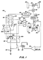
- Figures 1 to 4 show four different schematic diagrams which represent different drive and braking devices according to the invention.
- a vehicle for example an agricultural tractor, contains a drive machine 10 which drives a rear axle 14 via a transmission 12, a shaft 16 and a differential 17.
- the rear axle 14 carries a pair of rear drive wheels 16a, 16b, each having an associated service brake 18a, 18b.
- the drive machine 10 further drives a front axle 20 with the associated front wheels 21a, 21b via a pressure medium-actuated clutch 22 and a differential 24.
- the service brakes 18a, 18b are hydraulically operated by control cylinders in the usual way 26a, 26b actuated, the control cylinders being connected to corresponding brake pedals 28a, 28b via a conventional brake compensation valve 27.
- the clutch 22 is preferably a known spring-loaded clutch, which is held in the release position by pressure oil against the spring force, as described for example in DE-PS 29 46 477.
- the pressure in the clutch 22 is controlled by a valve 30, which in turn is actuated by a solenoid 32.
- the control circuit 40 shown in FIG. 1 controls the energized state of the magnetic coil 32.
- the control circuit 40 contains a two-pole, manually operable switch 42 which has three switching positions and is preferably arranged in the vehicle cabin (not shown).
- the switching pole 42a contains a first connection, which is connected to a voltage source 44, for example the battery of the vehicle.
- the first connection (input connection) can be connected to a second, a third or a fourth connection (output connections) by switching over.
- a second switching pole 42b of the switch 42 has a first connection (input connection) which is connected to the battery 44 via a contactor 46. This first connection of the switching pole 42b can also be connected by switching to a second, third and fourth connection (output connections).
- the control circuit 40 further includes a switch 48 which can be actuated by a brake pedal and has a first, a second and a third connection.
- the first terminal (input terminal) is connected to the second terminal of the switching pole 42a.
- the switching element of the switch 48 is operatively connected to the left brake pedal 28a in such a way that when the pedal 28a is not actuated, the the first port communicates with the second port, and when the pedal 28a is depressed, the first port is connected to the third port.
- a normally open brake operated switch 50 has a first and a second connection.
- the first terminal (input terminal) is connected to the second terminal of the switch 48.
- the second terminal (output terminal) is connected to one terminal of the solenoid 32.
- the switching element of the switch 50 is operatively connected to the right brake pedal 28b, so that the switch 50 is open when the brake is not applied and the switch contact is closed when the brake pedal 28b is depressed.
- a normally closed switch 52 operated by a brake pedal includes first and second terminals.
- the first connection (input connection) is connected to the third connection of the changeover switch 48 and to the second connection of the switching pole 42b.
- the second terminal (output terminal) is connected to one terminal of the solenoid 32.
- the switching element of the switch 52 is operatively connected to the right brake pedal 28b in such a way that the switch 52 is closed when the pedal 28b is not actuated and the switch is open when the pedal 28b is actuated.
- a speed sensor 54 detects the vehicle speed and delivers a signal corresponding to the speed to a comparison circuit 56.
- the comparison circuit 56 can contain a conventional comparator and amplifier which are connected to the coil 58 of the contactor 46 in such a way that the coil 58 only excites and the switch contact is only closed when the vehicle speed exceeds a predeterminable value.
- control circuit 40 causes clutch 22 to engage and engage the front wheels to the powertrain when both brakes are applied.
- the clutch 22 is released when only one of the two brake pedals 28a, 28b is depressed. If neither of the two brake pedals 28a, 28b is actuated, the clutch 22 is always engaged when the vehicle speed exceeds a certain speed value, for example approximately 14 km / h. In the latter case, the contactor 46 closes, whereby the solenoid 32 is energized and the clutch 22 is released.
- the solenoid 32 is connected to the battery 44 and is therefore excited.
- the clutch 22 is not in engagement.
- the solenoid 32 is not energized and the clutch 22 is engaged and connects the front wheels 21a, 21b to the drive train. Both in the" OFF “and in the "ON” position, the solenoid 32 is influenced neither by a brake application nor by the vehicle speed.
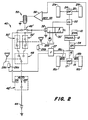
- FIG. 2 A second embodiment of the invention is shown in FIG. 2, in which the switch 50 (according to FIG. 1) has been replaced by a normally closed switch 50 'and the switch 52 (according to FIG. 1) by a normally open switch 52'.
- the switch contact 42b is omitted here and the switch 42 'contains an "ON" output, which is connected to a connection of the solenoid 32 and the second connection (output connection) of the switch 52'.
- the second terminal (output terminal) of the switch 50 ' is connected via a normally closed, actuated by a solenoid switch 46' to the solenoid 32 and the second terminal of the switch 52 '.
- the switch 46 ' is opened by a solenoid 58 and a comparator 56 when the vehicle speed exceeds a predeterminable speed value.
- the valve 30 ' shows a position in which the clutch 22 is connected to an oil return tank (clutch 22 in engagement). Here, the magnetic coil 32 is excited.
- FIG. 2 is similar to FIG. 1, with corresponding parts being assigned the same reference numbers.
- the clutch 22 is only brought into engagement by the control circuit 40 according to FIG. 2 when the coil 32 is energized.
- FIG. 3 A further embodiment of the present invention can be seen in FIG. 3.
- This alternative design is similar to that shown in Fig. 1, but differs in the following respects.
- the contactor 46 is directly connected to the first terminal (input terminal) of the switch 52.
- the battery 44 is connected directly to the first terminal (input terminal) of the changeover switch 48.
- a first manually operated switch 60 is included, which has a first terminal (input terminal) which is connected to the solenoid 32 and one side of an indicator lamp 42.
- a second terminal (output terminal) is connected to the second terminal of switches 50 and 52.
- a third connection is free.
- a fourth terminal (output terminal) is connected to the battery 44.
- the switch 60 can be actuated manually by means of a switching element by means of which the first connection of the switch 60 can be connected to its second, third or fourth connection.
- the circuit of FIG. 3 also includes a second hand operated switch 64 which has a first terminal connected to earth via an indicator lamp 62, a second terminal connected to the battery 44 and the other side of the indicator lamp 62, a third and a fourth free terminal and has a manually operable switching element through which the first terminal of the switch 64 connects to its second, third or fourth terminal is cash.
- the switching elements of the switches 60 and 64 are preferably mechanically coupled to one another, as is indicated in FIG. 3 by a dashed line.
- the lamps 62 and 64 are preferably located in the vehicle cabin, not shown, so that they provide the driver with an indication of the engaged state of the clutch 22 and whether the switches 60 and 64 are in the "AUTO" position.
- the circuit of FIG. 3 acts the same as the circuit of FIG. 1 except that the indicator lamp 62 illuminates whenever the clutch 22 is engaged and is always off when the clutch 22 is not engaged. Further, indicator lamp 66 only illuminates when switches 60 and 62 are in the "AUTO" position, i.e. when their first and second connections are connected to each other.
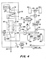
- FIG. 4 Another alternative embodiment of the invention is shown in FIG. 4. This design is similar to the design according to FIG. 3, except that the wiring of the first and second manually operated switches 70, 74 takes place differently from FIG. 3.
- the first manual switch 70 includes a first terminal (input terminal) which is connected to the solenoid 32 and one side of an indicator lamp 72, a second and fourth terminal (output terminals) which are connected together and connected to the second terminals of the switches 50 and 52 are a third, free connection and a switching element through which the first connection can be connected to any of the remaining connections.
- the second hand operated switch 74 includes a first terminal (input terminal) which is connected to the other side of the lamp 72 and the battery 44, a second terminal which is connected to earth via the indicator lamp 76, a third, free terminal, one fourth connection which is connected to the common connection between the switches 46, 48 and 52, and a switching element which is mechanically coupled to the switching element of the switch 70 and through which the first connection can be connected to any of the remaining connections.
- the circuit of FIG. 4 acts similarly to the circuit of FIG. 3, except that when switches 70 and 74 are in their "OFF" position, the clutch is only engaged when both are engaged Brake pedals 28a, 28b are actuated. For some areas, such as Europe, where higher transport speeds are permitted, it may be desirable to provide the four-wheel brake option even when switches 70 and 74 are in their "OFF" position.
Landscapes
- Engineering & Computer Science (AREA)
- Transportation (AREA)
- Mechanical Engineering (AREA)
- Physics & Mathematics (AREA)
- Fluid Mechanics (AREA)
- Chemical & Material Sciences (AREA)
- Combustion & Propulsion (AREA)
- Arrangement And Mounting Of Devices That Control Transmission Of Motive Force (AREA)
- Control Of Driving Devices And Active Controlling Of Vehicle (AREA)
- Arrangement And Driving Of Transmission Devices (AREA)
- Regulating Braking Force (AREA)
Priority Applications (1)
| Application Number | Priority Date | Filing Date | Title |
|---|---|---|---|
| AT89102393T ATE90628T1 (de) | 1988-02-16 | 1989-02-11 | Antriebs- und bremsvorrichtung fuer ein kraftfahrzeug. |
Applications Claiming Priority (4)
| Application Number | Priority Date | Filing Date | Title |
|---|---|---|---|
| US07/155,772 US4811811A (en) | 1988-02-16 | 1988-02-16 | Brake system for four-wheel drive vehicles |
| US07/257,574 US4878559A (en) | 1988-02-16 | 1988-10-14 | Brake system for four-wheel drive vehicles |
| US257574 | 1988-10-14 | ||
| US155772 | 1988-10-14 |
Publications (3)
| Publication Number | Publication Date |
|---|---|
| EP0329045A2 true EP0329045A2 (fr) | 1989-08-23 |
| EP0329045A3 EP0329045A3 (en) | 1990-08-22 |
| EP0329045B1 EP0329045B1 (fr) | 1993-06-16 |
Family
ID=26852599
Family Applications (1)
| Application Number | Title | Priority Date | Filing Date |
|---|---|---|---|
| EP89102393A Expired - Lifetime EP0329045B1 (fr) | 1988-02-16 | 1989-02-11 | Dispositif de propulsion et de freinage pour automobile |
Country Status (7)
| Country | Link |
|---|---|
| US (1) | US4878559A (fr) |
| EP (1) | EP0329045B1 (fr) |
| JP (1) | JP2882635B2 (fr) |
| DE (1) | DE58904671D1 (fr) |
| DK (1) | DK70889A (fr) |
| ES (1) | ES2041351T3 (fr) |
| NO (1) | NO890633L (fr) |
Cited By (4)
| Publication number | Priority date | Publication date | Assignee | Title |
|---|---|---|---|---|
| EP0411307A1 (fr) * | 1989-07-03 | 1991-02-06 | Deere & Company | Commande d'embrayage pour véhicules à moteur |
| EP0457742A1 (fr) * | 1990-05-14 | 1991-11-21 | Valmet Traktori Oy | Méthode et arrangement pour la mise en/hors marche d'une transmission de force motrice à un essieu de traction avant d'un tracteur ou d'une machine de travail |
| EP1958838A3 (fr) * | 2007-02-09 | 2011-03-02 | Deere & Company | Système de commande de véhicule |
| US20210289700A1 (en) * | 2016-08-04 | 2021-09-23 | The Toro Company | Auxiliary brake system for outdoor grounds maintenance vehicles having hydrostatic traction drive systems |
Families Citing this family (8)
| Publication number | Priority date | Publication date | Assignee | Title |
|---|---|---|---|---|
| US5248020A (en) * | 1992-03-23 | 1993-09-28 | Case Corporation | Drive system for a tractor |
| GB9226513D0 (en) * | 1992-12-19 | 1993-02-10 | Massey Ferguson Gmbh | Four wheel drive vehicles |
| US5551526A (en) * | 1994-09-23 | 1996-09-03 | New Holland North America, Inc. | Modulated FWD clutch for tractor braking |
| US5802489A (en) * | 1994-11-14 | 1998-09-01 | Case Corporation | Front wheel drive engagement control system for agricultural vehicles |
| US5531515A (en) * | 1995-05-08 | 1996-07-02 | Circosta; Vincent | Auxiliary brake system for four-wheel-drive vehicle |
| US8504249B2 (en) * | 2007-06-01 | 2013-08-06 | Deere & Company | Automatic control of mechanical front wheel drive using speed ratio |
| WO2008147364A1 (fr) * | 2007-06-01 | 2008-12-04 | Deere & Company | Activation temporaire de l'entraînement mécanique de roues avant |
| GB2466066A (en) | 2008-12-12 | 2010-06-16 | Agco Gmbh | Braking system having left and right brake pedals that are lockable together, and warning means to indicate the pedals are unlocked |
Family Cites Families (13)
| Publication number | Priority date | Publication date | Assignee | Title |
|---|---|---|---|---|
| US3081836A (en) * | 1959-05-30 | 1963-03-19 | Ferguson Res Ltd Harry | Vehicle braking control |
| FI51808C (fi) * | 1968-07-15 | 1977-04-12 | Rhone Poulenc Sa | Menetelmä uusien kasvainten naftaseenijohdannaisten valmistamiseksi. |
| US3963085A (en) * | 1974-10-17 | 1976-06-15 | Caterpillar Tractor Co. | Planetary four wheel drive system having plural modes of operation |
| JPS5275327U (fr) * | 1975-12-02 | 1977-06-06 | ||
| US4088208A (en) * | 1976-10-26 | 1978-05-09 | International Harvester Company | Transmission disconnect system |
| JPS53111937A (en) * | 1977-03-08 | 1978-09-29 | Iseki & Co Ltd | Front wheel drive clutch device for four-wheel drive power agricultural vehicle |
| DE3016788C2 (de) * | 1980-04-30 | 1986-12-18 | International Harvester Company Mbh, 4040 Neuss | Antriebs- und Bremsanordnung für Kraftfahrzeuge, insbesondere Ackerschlepper, mit zum Allradantrieb zuschaltbarer Radachse |
| JPS5766022A (en) * | 1980-10-09 | 1982-04-22 | Fuji Heavy Ind Ltd | Four-wheel drive vehicle |
| EP0128583B1 (fr) * | 1983-06-14 | 1988-12-14 | Robert Bosch Gmbh | Véhicule à traction sur les quatre roues |
| US4635743A (en) * | 1984-04-12 | 1987-01-13 | Dresser Industries, Inc. | Vehicle front wheel assist drive overspeed control system |
| US4711318A (en) * | 1985-04-30 | 1987-12-08 | Fuji Jukogyo Kabushiki Kaisha | System for controlling a transfer clutch of a four-wheel drive vehicle |
| JPS61249831A (ja) * | 1985-04-30 | 1986-11-07 | Fuji Heavy Ind Ltd | 4輪駆動装置の油圧制御装置 |
| DE3535090C2 (de) * | 1985-10-02 | 1994-05-05 | Teves Gmbh Alfred | Schlupfgeregelte Bremsanlage für Allrad-angetriebene Kraftfahrzeuge |
-
1988
- 1988-10-14 US US07/257,574 patent/US4878559A/en not_active Expired - Lifetime
-
1989
- 1989-02-11 ES ES198989102393T patent/ES2041351T3/es not_active Expired - Lifetime
- 1989-02-11 EP EP89102393A patent/EP0329045B1/fr not_active Expired - Lifetime
- 1989-02-11 DE DE8989102393T patent/DE58904671D1/de not_active Expired - Lifetime
- 1989-02-15 NO NO89890633A patent/NO890633L/no unknown
- 1989-02-15 DK DK070889A patent/DK70889A/da not_active Application Discontinuation
- 1989-02-16 JP JP1037318A patent/JP2882635B2/ja not_active Expired - Lifetime
Cited By (5)
| Publication number | Priority date | Publication date | Assignee | Title |
|---|---|---|---|---|
| EP0411307A1 (fr) * | 1989-07-03 | 1991-02-06 | Deere & Company | Commande d'embrayage pour véhicules à moteur |
| EP0457742A1 (fr) * | 1990-05-14 | 1991-11-21 | Valmet Traktori Oy | Méthode et arrangement pour la mise en/hors marche d'une transmission de force motrice à un essieu de traction avant d'un tracteur ou d'une machine de travail |
| EP1958838A3 (fr) * | 2007-02-09 | 2011-03-02 | Deere & Company | Système de commande de véhicule |
| US20210289700A1 (en) * | 2016-08-04 | 2021-09-23 | The Toro Company | Auxiliary brake system for outdoor grounds maintenance vehicles having hydrostatic traction drive systems |
| US12157443B2 (en) * | 2016-08-04 | 2024-12-03 | The Toro Company | Auxiliary brake system for outdoor grounds maintenance vehicles having hydrostatic traction drive systems |
Also Published As
| Publication number | Publication date |
|---|---|
| EP0329045B1 (fr) | 1993-06-16 |
| ES2041351T3 (es) | 1993-11-16 |
| NO890633L (no) | 1989-08-17 |
| DK70889D0 (da) | 1989-02-15 |
| US4878559A (en) | 1989-11-07 |
| JPH01254475A (ja) | 1989-10-11 |
| EP0329045A3 (en) | 1990-08-22 |
| DK70889A (da) | 1989-08-17 |
| JP2882635B2 (ja) | 1999-04-12 |
| DE58904671D1 (de) | 1993-07-22 |
| NO890633D0 (no) | 1989-02-15 |
Similar Documents
| Publication | Publication Date | Title |
|---|---|---|
| EP0259634B1 (fr) | Dispositif d'actionnement d'un embrayage | |
| DE3839710C2 (de) | Antiblockiersystem für ein allradgetriebenes Kraftfahrzeug | |
| EP0581124B1 (fr) | Système de commande pour transmission avec mode d'opération de secours | |
| DE4229041A1 (de) | Fahrzeug-bremssteuersystem | |
| DE19859806A1 (de) | Lenksystem für Kraftfahrzeuge | |
| EP0295396B1 (fr) | Système de freinage pour un véhicule dirigeable, à 2 ou plusieurs essieux, avec entraînement au moins sur les roues arrière | |
| EP0329045B1 (fr) | Dispositif de propulsion et de freinage pour automobile | |
| DE2014052A1 (de) | Vorrichtung zum selbsttätigen Steuern eines mechanischen Schaltgetriebes für Kraftfahrzeuge | |
| EP0128478A1 (fr) | Système de contrôle pour bloquer le différentiel | |
| DE3016788A1 (de) | Antriebs- und bremsanordnung fuer allradgetriebene kraftfahrzeuge, insbesondere ackerschlepper | |
| EP0688712B1 (fr) | Système de freinage pour un véhicule à moteur | |
| DE3208393A1 (de) | Lenkbremseinrichtung fuer eine druckmittelbetaetigte fahrzeugbremsanlage | |
| DE3636260A1 (de) | Kraftfahrzeug mit zumindest einer permanent angetriebenen achse sowie einer antriebsmaessig zuschaltbaren achse | |
| EP0388634A1 (fr) | Dispositif d'antiblocage et de limitation du glissement de traction | |
| EP0254113B1 (fr) | Installation hydraulique de frein de direction pour véhicule | |
| DE69311282T2 (de) | Bremsvorrichtung für ein Fahrzeug mit Vierradantrieb | |
| DE10145789A1 (de) | System zur Lenkbremsung mit elektrisch gesteuerten Ventilen | |
| DE3149110A1 (de) | Elektro-druckmittel-bremsanlage | |
| DE3421387C2 (fr) | ||
| EP0411307B1 (fr) | Commande d'embrayage pour véhicules à moteur | |
| EP0079543A1 (fr) | Installation de freinage à fluide sous pression | |
| DE3527959A1 (de) | Verfahren und vorrichtung zur vortriebsregelung | |
| EP0464375A1 (fr) | Système de freinage hydraulique | |
| DE68902121T2 (de) | Uebertragungsvorrichtung fuer fahrzeug mit vierradantrieb. | |
| DE4014295A1 (de) | Hydraulische zweikreisbremsanlage |
Legal Events
| Date | Code | Title | Description |
|---|---|---|---|
| PUAI | Public reference made under article 153(3) epc to a published international application that has entered the european phase |
Free format text: ORIGINAL CODE: 0009012 |
|
| AK | Designated contracting states |
Kind code of ref document: A2 Designated state(s): AT BE CH DE ES FR GB IT LI NL SE |
|
| 17P | Request for examination filed |
Effective date: 19900208 |
|
| PUAL | Search report despatched |
Free format text: ORIGINAL CODE: 0009013 |
|
| AK | Designated contracting states |
Kind code of ref document: A3 Designated state(s): AT BE CH DE ES FR GB IT LI NL SE |
|
| 17Q | First examination report despatched |
Effective date: 19920708 |
|
| ITF | It: translation for a ep patent filed | ||
| GRAA | (expected) grant |
Free format text: ORIGINAL CODE: 0009210 |
|
| AK | Designated contracting states |
Kind code of ref document: B1 Designated state(s): AT BE CH DE ES FR GB IT LI NL SE |
|
| REF | Corresponds to: |
Ref document number: 90628 Country of ref document: AT Date of ref document: 19930715 Kind code of ref document: T |
|
| REF | Corresponds to: |
Ref document number: 58904671 Country of ref document: DE Date of ref document: 19930722 |
|
| GBT | Gb: translation of ep patent filed (gb section 77(6)(a)/1977) |
Effective date: 19930625 |
|
| ET | Fr: translation filed | ||
| REG | Reference to a national code |
Ref country code: ES Ref legal event code: FG2A Ref document number: 2041351 Country of ref document: ES Kind code of ref document: T3 |
|
| PLBE | No opposition filed within time limit |
Free format text: ORIGINAL CODE: 0009261 |
|
| STAA | Information on the status of an ep patent application or granted ep patent |
Free format text: STATUS: NO OPPOSITION FILED WITHIN TIME LIMIT |
|
| 26N | No opposition filed | ||
| EAL | Se: european patent in force in sweden |
Ref document number: 89102393.9 |
|
| PGFP | Annual fee paid to national office [announced via postgrant information from national office to epo] |
Ref country code: CH Payment date: 20010125 Year of fee payment: 13 |
|
| PGFP | Annual fee paid to national office [announced via postgrant information from national office to epo] |
Ref country code: AT Payment date: 20010213 Year of fee payment: 13 |
|
| PGFP | Annual fee paid to national office [announced via postgrant information from national office to epo] |
Ref country code: BE Payment date: 20010221 Year of fee payment: 13 |
|
| PGFP | Annual fee paid to national office [announced via postgrant information from national office to epo] |
Ref country code: FR Payment date: 20010222 Year of fee payment: 13 |
|
| PGFP | Annual fee paid to national office [announced via postgrant information from national office to epo] |
Ref country code: ES Payment date: 20010223 Year of fee payment: 13 |
|
| PGFP | Annual fee paid to national office [announced via postgrant information from national office to epo] |
Ref country code: NL Payment date: 20010227 Year of fee payment: 13 |
|
| REG | Reference to a national code |
Ref country code: GB Ref legal event code: IF02 |
|
| PGFP | Annual fee paid to national office [announced via postgrant information from national office to epo] |
Ref country code: SE Payment date: 20020107 Year of fee payment: 14 |
|
| PG25 | Lapsed in a contracting state [announced via postgrant information from national office to epo] |
Ref country code: AT Free format text: LAPSE BECAUSE OF NON-PAYMENT OF DUE FEES Effective date: 20020211 |
|
| PG25 | Lapsed in a contracting state [announced via postgrant information from national office to epo] |
Ref country code: SE Free format text: LAPSE BECAUSE OF NON-PAYMENT OF DUE FEES Effective date: 20020212 Ref country code: ES Free format text: LAPSE BECAUSE OF NON-PAYMENT OF DUE FEES Effective date: 20020212 |
|
| PG25 | Lapsed in a contracting state [announced via postgrant information from national office to epo] |
Ref country code: CH Free format text: LAPSE BECAUSE OF NON-PAYMENT OF DUE FEES Effective date: 20020228 Ref country code: LI Free format text: LAPSE BECAUSE OF NON-PAYMENT OF DUE FEES Effective date: 20020228 Ref country code: BE Free format text: LAPSE BECAUSE OF NON-PAYMENT OF DUE FEES Effective date: 20020228 |
|
| BERE | Be: lapsed |
Owner name: DEERE & CY Effective date: 20020228 |
|
| PG25 | Lapsed in a contracting state [announced via postgrant information from national office to epo] |
Ref country code: NL Free format text: LAPSE BECAUSE OF NON-PAYMENT OF DUE FEES Effective date: 20020901 |
|
| EUG | Se: european patent has lapsed |
Ref document number: 89102393.9 |
|
| REG | Reference to a national code |
Ref country code: CH Ref legal event code: PL |
|
| PG25 | Lapsed in a contracting state [announced via postgrant information from national office to epo] |
Ref country code: FR Free format text: LAPSE BECAUSE OF NON-PAYMENT OF DUE FEES Effective date: 20021031 |
|
| NLV4 | Nl: lapsed or anulled due to non-payment of the annual fee |
Effective date: 20020901 |
|
| REG | Reference to a national code |
Ref country code: FR Ref legal event code: ST |
|
| REG | Reference to a national code |
Ref country code: ES Ref legal event code: FD2A Effective date: 20030922 |
|
| PGFP | Annual fee paid to national office [announced via postgrant information from national office to epo] |
Ref country code: GB Payment date: 20080227 Year of fee payment: 20 Ref country code: DE Payment date: 20080121 Year of fee payment: 20 Ref country code: IT Payment date: 20080228 Year of fee payment: 20 |
|
| REG | Reference to a national code |
Ref country code: GB Ref legal event code: PE20 Expiry date: 20090210 |
|
| PG25 | Lapsed in a contracting state [announced via postgrant information from national office to epo] |
Ref country code: GB Free format text: LAPSE BECAUSE OF EXPIRATION OF PROTECTION Effective date: 20090210 |