EP0329084A2 - Vorrichtung zum Festhalten eines beweglichen Schranks - Google Patents
Vorrichtung zum Festhalten eines beweglichen Schranks Download PDFInfo
- Publication number
- EP0329084A2 EP0329084A2 EP89102524A EP89102524A EP0329084A2 EP 0329084 A2 EP0329084 A2 EP 0329084A2 EP 89102524 A EP89102524 A EP 89102524A EP 89102524 A EP89102524 A EP 89102524A EP 0329084 A2 EP0329084 A2 EP 0329084A2
- Authority
- EP
- European Patent Office
- Prior art keywords
- cabinet
- caster
- leg member
- apparatus body
- disposed
- Prior art date
- Legal status (The legal status is an assumption and is not a legal conclusion. Google has not performed a legal analysis and makes no representation as to the accuracy of the status listed.)
- Granted
Links
- 230000003100 immobilizing effect Effects 0.000 title claims abstract description 5
- 230000000717 retained effect Effects 0.000 abstract 1
- 238000000151 deposition Methods 0.000 description 3
- 230000002459 sustained effect Effects 0.000 description 2
- 238000010586 diagram Methods 0.000 description 1
- 238000007689 inspection Methods 0.000 description 1
- 238000012423 maintenance Methods 0.000 description 1
Images


Classifications
-
- A—HUMAN NECESSITIES
- A47—FURNITURE; DOMESTIC ARTICLES OR APPLIANCES; COFFEE MILLS; SPICE MILLS; SUCTION CLEANERS IN GENERAL
- A47B—TABLES; DESKS; OFFICE FURNITURE; CABINETS; DRAWERS; GENERAL DETAILS OF FURNITURE
- A47B53/00—Cabinets or racks having several sections one behind the other
-
- A—HUMAN NECESSITIES
- A47—FURNITURE; DOMESTIC ARTICLES OR APPLIANCES; COFFEE MILLS; SPICE MILLS; SUCTION CLEANERS IN GENERAL
- A47B—TABLES; DESKS; OFFICE FURNITURE; CABINETS; DRAWERS; GENERAL DETAILS OF FURNITURE
- A47B96/00—Details of cabinets, racks or shelf units not covered by a single one of groups A47B43/00 - A47B95/00; General details of furniture
-
- A—HUMAN NECESSITIES
- A47—FURNITURE; DOMESTIC ARTICLES OR APPLIANCES; COFFEE MILLS; SPICE MILLS; SUCTION CLEANERS IN GENERAL
- A47B—TABLES; DESKS; OFFICE FURNITURE; CABINETS; DRAWERS; GENERAL DETAILS OF FURNITURE
- A47B88/00—Drawers for tables, cabinets or like furniture; Guides for drawers
- A47B88/40—Sliding drawers; Slides or guides therefor
- A47B88/41—Drawers with castors, rollers or wheels, supported directly on a surface below, e.g. on a floor, shelf or desktop
-
- A—HUMAN NECESSITIES
- A47—FURNITURE; DOMESTIC ARTICLES OR APPLIANCES; COFFEE MILLS; SPICE MILLS; SUCTION CLEANERS IN GENERAL
- A47B—TABLES; DESKS; OFFICE FURNITURE; CABINETS; DRAWERS; GENERAL DETAILS OF FURNITURE
- A47B91/00—Feet for furniture in general
Definitions
- the present invention relates to an apparatus for immobilizing a movable cabinet, a body of said apparatus being housed in the cabinet so as to be drawn therefrom, and for example, to an apparatus for immobilizing a cabinet of a bill deposit and dispense machine of a type to be installed in a bank so as to be used by clerks.
- FIG. 6 shows a cabinet and a body of the apparatus drawn therefrom.
- a support rail 53 On an inner surface of a side plate of a cabinet 51, there is fixedly secured a support rail 53.
- a slide member 54 On a side surface of the apparatus body 52, there is fixed a slide member 54, which slidably engages with the rail 53 in a longitudinal direction thereof.
- casters 57 In the four corner positions of the bottom surface of the apparatus body 52, there are attached four casters 57, respectively.
- the apparatus body 52 is inserted from an opening of an end of the cabinet 51 so as to be housed therein; furthermore, the apparatus body 52 can be drawn therefrom when the slide member 54 slides along the rail 53 so that the casters 57 move through rotating motion thereof on a floor surface.
- the cabinet 51 is provided with casters 55 each having a stopper in the four corner positions in the bottom surface
- a stopper lever 56 is operated to cause the stopper to act upon each caster 55, thereby preventing unnecessary movement of the cabinet 51.
- the cabinet 51 is provided with four casters 55 and the apparatus body 52 is also provided with four casters 57, namely, a large number of casters are employed; in consequence, it requires a complicated operation to adjust the height of the casters when the apparatus body 52 is drawn.
- a first caster disposed on a rear bottom surface of the cabinet
- a second caster disposed on a front bottom surface of the cabinet
- leg members disposed on a front bottom surface of the cabinet.
- the total number of the first and second casters is at least three.
- the cabinet is movable.
- the leg member is provided at lower end therof with a flat plate to be brought into contact with a floor surface.
- the leg member can be projected down to a position below the lower end of the second caster of the apparatus body housed in the cabinet and can be extracted up to a position above the lower end of the second caster.
- the cabinet by housing the apparatus body in the cabinet and by moving the leg members up to a position above the lower end of the second caster, the cabinet can be moved through a rotating movement of the first and second casters.
- the leg membesr need only be projected to a position such that the second caster of the apparatus body is slightly separated from the floor surface.
- the weight of the apparatus body is applied onto the leg members, and since each leg member has a flat plate to be brought into contact with the floor surface, there appears a large statical friction between the flat plate and the floor surface, which enables the cabinet to be securedly immobilized.
- the cabinet can be moved or immobilized.
- the bill deposit and dispense machine is installed in a bank or the like for usages therein such that a clerk inserts therein bills for a depositing transaction or bills are discharged therefrom for a payment transaction.
- the bills inserted into the machine are checked for the number of bills as well as for the kinds of bills so as to count the total amount thereof; and finally, the bills are stored in cartridges according to bill kinds in the machine.
- Bills to be paid are fed from the cartridges so as to be ejected from a discharge outlet.
- the bill deposit and dispense machine is connected to other terminals (including a terminal to input an amount and an account number and a terminal to read data from a passbook and to print transaction data on the passbook) and a main controller such that the machine operates under control of the main controller based on data inputted from these terminals.
- the bill deposit and dispense machine is configured to be shared between two tellers.
- two desks are respectively located on the right and left sides of the machine, and the terminals are installed on each desk. These clerks operate the bill deposit and dispense machine from the right and left positions, respectively.
- the bill deposit and dispense machine includes a cabinet 1 and a machine body 2.
- the cabinet 1 is a box or a frame having a shape of a parallelepiped and is open in the front and bottom sides.
- the machine body 2 is housed in the cabinet 1 so as to be drawn from the opening of the front side into the outside, which will be described later.
- the machine body 2 are provided with an upper panel 11 in an upper portion of the front section and a lower panel 12 in a lower portion of the front section.
- the upper panel 11 is provided with a bill insert inlet 13, a bill discharge outlet 14 having a shutter, a left start key 15 to be employed by the clerk on the left side to start the depositing and withdrawal operations, a right start key 16 to be employed by the clerk on the right side to start the depositing and withdrawal operations, a display 17 to dispay various messages, a ten-key pad 18 to set various modes, and an error display 19 to display positions of a paper jam and the like.
- the lower panel 12 can be freely opened and closed and is provided with a reset key 21 and a key 22 for the open and close the panel 12. It is possible to open the lower panel 12 to draw a bill storing cartridge 23 disposed in the body toward the forward direction.
- brackets 3a In the left and right positions of a bottom surface member disposed only in the rear section of the cabinet 1, there is fixed brackets 3a to which rear casters 3 are rotably attached.
- leg members 5 In the left and right sides of the lower portion of the front section of the cabinet 1, there is disposed leg members 5 to project downward and to retract upward, which will be described later.
- front casters 4 In addition, in a lower portion of the front section of the machine body 1, there is rotably disposed front casters 4 on the right and left sides thereof.
- the side surfaces of the cabinet 1 include a frame and a side plate 38 fixed thereon.
- the frame includes a plurality of vertical members 35 and a horizontal member 36 linking bottom ends of these vertical members 35.
- a first rail 31 which has substantially a U shape in a cross-sectional plane thereof and which horizontally extends in the forward and backward directions is fixedly secured on the vertical members 35 at inner bottom portions of the side surface of the cabinet 1.
- a second rail 32 similarly having a substantially in shape in a cross-sectional plane thereof is engaged via balls 33 with the first rail 31 so as to be slidable in the longitudinal direction of the first rail 31.
- a bottom plate 24 constituting the frame of the machine body 2 rises at both sides thereof so as to form support sections 24a.
- a slid member 26 which horizontally extends in the forward and backward directions.
- the slide member 26 is received via balls 34 onto the second rail 32 so as to be slidable in the longitudinal direction of the second rail 32.
- the leg member 5 comprises a screw rod 5a and a flat plate 5b attached to a bottom end of the screw rod 5a.
- the flat plate 5b is capable of being brought into contact with a floor surface to establish an areal contact. It is preferable to attach a friction plate on the bottom surface of the flat plate 5b.
- a front end portion of a horizontal member 36 constituting the cabinet 1 there is bored a hole in which a nut 37 is fixedly secured.
- the screw rod 5a of the leg member 5 is passed through the hole so as to be engaged with the nut 37.
- the leg member 5a By rotating the screw rod 5a, the leg member 5 is vertically moved (extended or retracted.)
- brackets 25 on the bottom plate 24 such that front casters 4 each are rotably mounted on a shaft 4a between the bracket 25 and the support sections 24a.
- the leg member 5 when the bill deposit and dispense machine is to be moved, as shown in FIG. 5, the leg member 5 is retracted such that the lower end thereof is located at a position above the lower end of the front caster 4. As a corresponding, the machine is supported by the front and rear casters 3 and 4 and is set to the movable state.
- the screw rod 5a of the leg member 5 at the retracted (raised) position projects toward the front side of the second rail 32, which prevents the second rail 32 from sliding toward the forward direction.
- the lock mechanism is configured as follows. That is, when the machine body 2 is drawn out therefrom, the second rail 32 first slides in the forward direction, so that at a point where the second rail 32 reaches the draw limit position, the locked state established between the secnd rail 32 and the slide member 26 is released.
- a stopper 27 is disposed in the slide member 26 so as to engage with the projected screw rod 5a. With the provision of the stopper 27, it can be prevented in an operation to move the the machine that the machine body 2 is mistakenly drawn out from the cabinet 1.
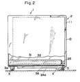
- the leg member 5 In order to install the bill deposit and dispense machine at a predetermined position, the leg member 5 is adjusted as shown in FIG. 2 such that the lower end thereof is projected to a position below the lower end of the second caster 4.
- the second caster 4 is slightly separated from the floor surface, which causes the machine to be supported by the first caster 3 and the leg member 5. Since a flat plate 5b is fixed on the lower end of the leg member 5 and the flat plate 5b is brought into contact with a broad area of the floor surface; furthermore, the leg member 5 receives the weight of the machine body 2, there appears a large statical frictional force to securedly retain the machine in a stationary state.
- the second caster 4 is brought into contact with the floor surface as shown in FIG. 3, namely, the machine body 2 is then supported by the leg member 5 and the second caster 4. Since the cabinet 1 is smaller in the weight than the machine body 2, there may appear a case where the first caster 3 of the cabinet 1 leaves from the floor surface or a case where the rails 31 and 32 and the slid member 26 slightly bend such that the first and second casters 3 and 4 are brought into contact with the floor surface. In either case, since the leg member 5 is brought into contact with the floor surface, the machine body 2 is sustained in the stationary state. In this state, the machine body 2 undergoes the maintenance, inspection, and the like.
Landscapes
- Casings For Electric Apparatus (AREA)
- Legs For Furniture In General (AREA)
- Washing And Drying Of Tableware (AREA)
- Vending Machines For Individual Products (AREA)
- Handcart (AREA)
- Drawers Of Furniture (AREA)
- Control Of Vending Devices And Auxiliary Devices For Vending Devices (AREA)
- Fittings On The Vehicle Exterior For Carrying Loads, And Devices For Holding Or Mounting Articles (AREA)
- Financial Or Insurance-Related Operations Such As Payment And Settlement (AREA)
Applications Claiming Priority (2)
| Application Number | Priority Date | Filing Date | Title |
|---|---|---|---|
| JP63032581A JPH01211095A (ja) | 1988-02-15 | 1988-02-15 | キャビネットの静止装置 |
| JP32581/88 | 1988-02-15 |
Publications (3)
| Publication Number | Publication Date |
|---|---|
| EP0329084A2 true EP0329084A2 (de) | 1989-08-23 |
| EP0329084A3 EP0329084A3 (de) | 1991-07-24 |
| EP0329084B1 EP0329084B1 (de) | 1994-10-19 |
Family
ID=12362841
Family Applications (1)
| Application Number | Title | Priority Date | Filing Date |
|---|---|---|---|
| EP89102524A Expired - Lifetime EP0329084B1 (de) | 1988-02-15 | 1989-02-14 | Vorrichtung zum Festhalten eines beweglichen Schranks |
Country Status (7)
| Country | Link |
|---|---|
| US (1) | US5046790A (de) |
| EP (1) | EP0329084B1 (de) |
| JP (1) | JPH01211095A (de) |
| KR (1) | KR930008626B1 (de) |
| AT (1) | ATE112944T1 (de) |
| DE (1) | DE68918881T2 (de) |
| ES (1) | ES2063772T3 (de) |
Cited By (1)
| Publication number | Priority date | Publication date | Assignee | Title |
|---|---|---|---|---|
| EP1530924A1 (de) * | 2003-11-13 | 2005-05-18 | Kokuyo Co., Ltd. | Objekthaltevorrichtungseinheit |
Families Citing this family (15)
| Publication number | Priority date | Publication date | Assignee | Title |
|---|---|---|---|---|
| JPH0724341B2 (ja) * | 1989-12-28 | 1995-03-15 | 株式会社日立製作所 | 転倒防止脚を備える電子機器筺体 |
| US5215367A (en) * | 1992-05-22 | 1993-06-01 | Amana Refrigeration, Inc. | Refrigerator door hinge |
| US6408482B1 (en) | 1997-09-09 | 2002-06-25 | Kimball International, Inc. | Standardized furniture unit and bracket therefor |
| JP3697936B2 (ja) * | 1998-04-20 | 2005-09-21 | 株式会社日立製作所 | 検体ラック取扱装置 |
| AU2002257269A1 (en) * | 2001-05-15 | 2002-11-25 | Prima Corporation | A cabinet for mounting electronic equipment |
| US6817687B1 (en) * | 2002-11-15 | 2004-11-16 | Unisys Corporation | Frame to floor anchoring system and method for using the same |
| US7077369B2 (en) * | 2003-07-23 | 2006-07-18 | Hardin Optical Co. | Stable tripod for telescope |
| KR100611317B1 (ko) * | 2004-08-28 | 2006-08-10 | 삼성전자주식회사 | 냉장고 |
| JP5559630B2 (ja) * | 2010-07-29 | 2014-07-23 | ヤマハ発動機株式会社 | 電子部品搬送装置および実装機 |
| JP2012232370A (ja) * | 2011-04-28 | 2012-11-29 | Seiko Epson Corp | ロボットコントローラー、簡易設置型ロボット、及び簡易設置型ロボットの制御方法 |
| KR101880085B1 (ko) * | 2011-12-07 | 2018-07-23 | 삼성전자주식회사 | 냉장고 |
| US9717338B2 (en) * | 2013-09-06 | 2017-08-01 | Ralph Lipsey Barnett | Anti-tip roller |
| KR20200008816A (ko) * | 2018-07-17 | 2020-01-29 | 주식회사 위니아대우 | 냉장고 |
| CN111093340B (zh) * | 2019-12-26 | 2022-02-08 | 安徽省墨凡嘉羽绒制品有限公司 | 一种羽绒服生产工序控制柜用安装结构 |
| US20220361667A1 (en) | 2021-05-14 | 2022-11-17 | Richard D. Cornell | Under Sink Cabinet With Movable Bottom Panel |
Family Cites Families (9)
| Publication number | Priority date | Publication date | Assignee | Title |
|---|---|---|---|---|
| US849999A (en) * | 1905-12-27 | 1907-04-09 | Augustin Hendricks | Combined packing-box and stand. |
| US2299688A (en) * | 1939-06-29 | 1942-10-20 | Gen Motors Corp | Domestic appliance |
| US2503020A (en) * | 1946-08-06 | 1950-04-04 | Bailey Theodore | Cabinet having open-sided drawers |
| US2803510A (en) * | 1954-04-02 | 1957-08-20 | Gen Electric | Cabinet, including retractable caster device |
| US2897910A (en) * | 1955-03-18 | 1959-08-04 | Orus C Steely | Reference service cart |
| US3413663A (en) * | 1967-02-23 | 1968-12-03 | David T. Swann | Combination stretcher, table, chair combination |
| US3482894A (en) * | 1967-12-19 | 1969-12-09 | Umc Ind | Cabinet with casters and leveling means |
| CA1008124A (en) * | 1975-08-21 | 1977-04-05 | Kalman I. Krakow | Darkroom module |
| US4784446A (en) * | 1987-06-08 | 1988-11-15 | Herman Miller, Inc. | Tool cabinet |
-
1988
- 1988-02-15 JP JP63032581A patent/JPH01211095A/ja active Pending
-
1989
- 1989-02-10 US US07/308,772 patent/US5046790A/en not_active Expired - Fee Related
- 1989-02-14 ES ES89102524T patent/ES2063772T3/es not_active Expired - Lifetime
- 1989-02-14 DE DE68918881T patent/DE68918881T2/de not_active Expired - Lifetime
- 1989-02-14 EP EP89102524A patent/EP0329084B1/de not_active Expired - Lifetime
- 1989-02-14 AT AT89102524T patent/ATE112944T1/de not_active IP Right Cessation
- 1989-02-15 KR KR1019890001705A patent/KR930008626B1/ko not_active Expired - Lifetime
Cited By (2)
| Publication number | Priority date | Publication date | Assignee | Title |
|---|---|---|---|---|
| EP1530924A1 (de) * | 2003-11-13 | 2005-05-18 | Kokuyo Co., Ltd. | Objekthaltevorrichtungseinheit |
| US7281774B2 (en) | 2003-11-13 | 2007-10-16 | Kokuyo Co., Ltd. | Object supporting unit |
Also Published As
| Publication number | Publication date |
|---|---|
| EP0329084A3 (de) | 1991-07-24 |
| JPH01211095A (ja) | 1989-08-24 |
| DE68918881D1 (de) | 1994-11-24 |
| KR930008626B1 (ko) | 1993-09-11 |
| ES2063772T3 (es) | 1995-01-16 |
| US5046790A (en) | 1991-09-10 |
| ATE112944T1 (de) | 1994-11-15 |
| EP0329084B1 (de) | 1994-10-19 |
| DE68918881T2 (de) | 1995-06-08 |
| KR890012596A (ko) | 1989-09-18 |
Similar Documents
| Publication | Publication Date | Title |
|---|---|---|
| US5046790A (en) | Apparatus for immobilizing movable cabinet | |
| US3211504A (en) | Dispenser for rolls of paper | |
| DE69619567T2 (de) | Verkaufsautomat für zeitungen und zeitschriften | |
| EP1230138B1 (de) | Verkaufsautomat zum pro stückverkauf von zeitungen | |
| US4869006A (en) | Device for the cyclic rearrangement of a pile of sheets | |
| US4473172A (en) | Vertical article dispenser | |
| CA1132107A (en) | Shelf locking apparatus | |
| US4718532A (en) | Coin operated vending machines for newspapers or the like | |
| US4140242A (en) | Newspaper and periodical single-copy vending machine | |
| US4258861A (en) | Single-paper vending apparatus | |
| US5178299A (en) | Newspaper vending machine | |
| US4583658A (en) | Single newspaper vending machine | |
| US4319695A (en) | Vendor for flat articles | |
| US7819282B2 (en) | Newspaper vending machine | |
| US4753387A (en) | Bag depository for drive-up banking and the like | |
| US6467649B1 (en) | Single vend newspaper dispensing machine | |
| GB2096229A (en) | Anti-tilt arrangement for multi- drawer cabinet | |
| US3318478A (en) | Vending machine | |
| US2703664A (en) | Magazine-type dispenser | |
| US3831809A (en) | Single-vend dispensing machine | |
| US5492213A (en) | Single copy newspaper magazine dispenser | |
| US6112941A (en) | Single vend newspaper vending machine | |
| US4239127A (en) | Gravity assisted newspaper vending machine with customer-operated newspaper lift device | |
| JPH07336056A (ja) | 電子機器の転倒防止装置 | |
| JP4653295B2 (ja) | 紙幣回収払出し装置 |
Legal Events
| Date | Code | Title | Description |
|---|---|---|---|
| PUAI | Public reference made under article 153(3) epc to a published international application that has entered the european phase |
Free format text: ORIGINAL CODE: 0009012 |
|
| 17P | Request for examination filed |
Effective date: 19890214 |
|
| AK | Designated contracting states |
Kind code of ref document: A2 Designated state(s): AT BE CH DE ES FR GB GR IT LI LU NL SE |
|
| PUAL | Search report despatched |
Free format text: ORIGINAL CODE: 0009013 |
|
| AK | Designated contracting states |
Kind code of ref document: A3 Designated state(s): AT BE CH DE ES FR GB GR IT LI LU NL SE |
|
| RHK1 | Main classification (correction) |
Ipc: A47B 31/00 |
|
| 17Q | First examination report despatched |
Effective date: 19930309 |
|
| GRAA | (expected) grant |
Free format text: ORIGINAL CODE: 0009210 |
|
| AK | Designated contracting states |
Kind code of ref document: B1 Designated state(s): AT BE CH DE ES FR GB GR IT LI LU NL SE |
|
| PG25 | Lapsed in a contracting state [announced via postgrant information from national office to epo] |
Ref country code: IT Free format text: LAPSE BECAUSE OF FAILURE TO SUBMIT A TRANSLATION OF THE DESCRIPTION OR TO PAY THE FEE WITHIN THE PRESCRIBED TIME-LIMIT;WARNING: LAPSES OF ITALIAN PATENTS WITH EFFECTIVE DATE BEFORE 2007 MAY HAVE OCCURRED AT ANY TIME BEFORE 2007. THE CORRECT EFFECTIVE DATE MAY BE DIFFERENT FROM THE ONE RECORDED. Effective date: 19941019 Ref country code: NL Effective date: 19941019 Ref country code: CH Effective date: 19941019 Ref country code: BE Effective date: 19941019 Ref country code: AT Effective date: 19941019 Ref country code: GR Free format text: LAPSE BECAUSE OF FAILURE TO SUBMIT A TRANSLATION OF THE DESCRIPTION OR TO PAY THE FEE WITHIN THE PRESCRIBED TIME-LIMIT Effective date: 19941019 Ref country code: LI Effective date: 19941019 |
|
| REF | Corresponds to: |
Ref document number: 112944 Country of ref document: AT Date of ref document: 19941115 Kind code of ref document: T |
|
| REF | Corresponds to: |
Ref document number: 68918881 Country of ref document: DE Date of ref document: 19941124 |
|
| REG | Reference to a national code |
Ref country code: ES Ref legal event code: FG2A Ref document number: 2063772 Country of ref document: ES Kind code of ref document: T3 |
|
| PG25 | Lapsed in a contracting state [announced via postgrant information from national office to epo] |
Ref country code: SE Effective date: 19950119 |
|
| ET | Fr: translation filed | ||
| REG | Reference to a national code |
Ref country code: CH Ref legal event code: PL |
|
| PG25 | Lapsed in a contracting state [announced via postgrant information from national office to epo] |
Ref country code: LU Free format text: LAPSE BECAUSE OF NON-PAYMENT OF DUE FEES Effective date: 19950228 |
|
| NLV1 | Nl: lapsed or annulled due to failure to fulfill the requirements of art. 29p and 29m of the patents act | ||
| PLBE | No opposition filed within time limit |
Free format text: ORIGINAL CODE: 0009261 |
|
| STAA | Information on the status of an ep patent application or granted ep patent |
Free format text: STATUS: NO OPPOSITION FILED WITHIN TIME LIMIT |
|
| 26N | No opposition filed | ||
| REG | Reference to a national code |
Ref country code: GB Ref legal event code: IF02 |
|
| REG | Reference to a national code |
Ref country code: GB Ref legal event code: 732E |
|
| PGFP | Annual fee paid to national office [announced via postgrant information from national office to epo] |
Ref country code: ES Payment date: 20080221 Year of fee payment: 20 |
|
| PGFP | Annual fee paid to national office [announced via postgrant information from national office to epo] |
Ref country code: GB Payment date: 20080218 Year of fee payment: 20 |
|
| PGFP | Annual fee paid to national office [announced via postgrant information from national office to epo] |
Ref country code: FR Payment date: 20080218 Year of fee payment: 20 Ref country code: DE Payment date: 20080229 Year of fee payment: 20 |
|
| REG | Reference to a national code |
Ref country code: GB Ref legal event code: PE20 Expiry date: 20090213 |
|
| REG | Reference to a national code |
Ref country code: ES Ref legal event code: FD2A Effective date: 20090216 |
|
| PG25 | Lapsed in a contracting state [announced via postgrant information from national office to epo] |
Ref country code: GB Free format text: LAPSE BECAUSE OF EXPIRATION OF PROTECTION Effective date: 20090213 |
|
| PG25 | Lapsed in a contracting state [announced via postgrant information from national office to epo] |
Ref country code: ES Free format text: LAPSE BECAUSE OF EXPIRATION OF PROTECTION Effective date: 20090216 |