EP0329143A1 - Entladungslampe - Google Patents
Entladungslampe Download PDFInfo
- Publication number
- EP0329143A1 EP0329143A1 EP89102691A EP89102691A EP0329143A1 EP 0329143 A1 EP0329143 A1 EP 0329143A1 EP 89102691 A EP89102691 A EP 89102691A EP 89102691 A EP89102691 A EP 89102691A EP 0329143 A1 EP0329143 A1 EP 0329143A1
- Authority
- EP
- European Patent Office
- Prior art keywords
- bulb
- electrodes
- discharge lamp
- discharge
- glass bulb
- Prior art date
- Legal status (The legal status is an assumption and is not a legal conclusion. Google has not performed a legal analysis and makes no representation as to the accuracy of the status listed.)
- Granted
Links
Images



Classifications
-
- H—ELECTRICITY
- H01—ELECTRIC ELEMENTS
- H01J—ELECTRIC DISCHARGE TUBES OR DISCHARGE LAMPS
- H01J65/00—Lamps without any electrode inside the vessel; Lamps with at least one main electrode outside the vessel
- H01J65/04—Lamps in which a gas filling is excited to luminesce by an external electromagnetic field or by external corpuscular radiation, e.g. for indicating plasma display panels
- H01J65/042—Lamps in which a gas filling is excited to luminesce by an external electromagnetic field or by external corpuscular radiation, e.g. for indicating plasma display panels by an external electromagnetic field
- H01J65/046—Lamps in which a gas filling is excited to luminesce by an external electromagnetic field or by external corpuscular radiation, e.g. for indicating plasma display panels by an external electromagnetic field the field being produced by using capacitive means around the vessel
Definitions
- the present invention relates to a discharge lamp in which a pair of electrodes are provided on the outer surface of a substantially straight glass bulb, to the inner surface of which is applied fluophor, wherein discharge gas such as rare gas or rare gas plus metal vapor is charged therewithin.
- FIG.2 shows a fluorescent lamp of an aperture type with a cut away view in part, disclosed as a prior art in Japanese Patent KOKAI publication No.61-185857.
- an inert gas and metal vapor such as mercury.
- a reflection film 4 On the inner wall of the glass bulb 1 is provided a reflection film 4 except for an opening 2 and a fluophor 3 on the reflection film 4.
- a pair of metal electrodes 5,6 are provided on the outer circumferential surface of the bulb in the proximity of the both ends of the bulb.
- the metal vapor in the glass bulb 1 is excited to emit ultraviolet rays, which in turn causes a visible light to be emitted with the aid of fluophor applied on the inner wall of the bulb 1.
- a discharge lamp is of a simple construction and easy to manufacture. Also the discharge lamp is of a long life since it has no filaments therein and is free from a problem that portions near the electrodes become black in a long run.
- the discharge lamp provides more amount of light with increasing area of the electrodes 5,6 which contacts with the outer circumferential surface of the glass bulb.
- the electrodes enclose the glass bulb 1 in the vicinity of both ends thereof and thus decreases the amount of light emitted, thereby reducing effective length in the longitudinal direction of the glass bulb 1. Extending the electrodes in the longitudinal direction increases the area of the electrodes providing more light. On the other hand, extending the electrodes causes a shorter effective length of the bulb 1 that contributes to light emission.
- the discharge lamps in which a high frequency is applied across both end portions thereof to cause the discharge develop a positive column at a middle portion of the bulb. The positive column is highly efficient and uniform in light intensity but the long distance between the electrodes requires a high voltage for initiating discharge.
- FIG.9 is a longitudinal cross-sectional view of a fluorescent lamp disclosed in Japanese Patent KOKAI publication No.60-12660 and FIG.10 an enlarged transverse cross-sectional view thereof.
- the glass bulb 1 in the glass bulb 1 is charged the mercury vapor and the rare gas 2 and is applied the fluophor 3 on the entire inner wall thereof.
- On the outer circumferential surface of the glass bulb 1 are disposed a pair of electrodes 5,6.
- the high frequency voltage applied causes discharge 8 in the bulb 1. This discharge excites the mercury atoms to thereby develop ultraviolet rays which in turn cause the fluophor to emit a visible light.
- Such type of fluorescent lamp suffers from a problem that strong impact by electrons and ions causes deterioration of the fluophor at the portions 4a,4b on the inner surface of the bulb opposite to the electrodes 5,6, causing the amount of light to decrease with time. Therefore the life-time of the discharge lamp will be shorter in optical information apparatuses, particularly a facsimile apparatus where a change in light output with time can be a problem.
- An object of the present invention is to provide a discharge lamp in which the area of the electrodes contacting with the circumferential surface of the discharge bulb can be made larger without extending the electrode mounted on both end portions of a straight glass bulb in the longitudinal direction thereof, thereby obtaining a long effective length of the glass bulb. Uneven surface or ridges and furrows formed on the both end portions of the glass bulb cause an increased surface area of the bulb contacting with the electrodes at that portion.
- the electrodes are configured to the ridges and furrows 10a,11a.
- Another object of the invention is to provide a discharge lamp in which circumferential length of the straight glass bulb is made larger than that of light emitting portion thereof, thereby obtaining a long effective length of the glass bulb.
- Still another object of the invention is to provide a discharge lamp of a simple construction, having a low discharge-initiating voltage, but not being impaired emitted light therefrom.
- Yet another object of the invention is to provide a long-life fluorescent lamp but not having significant change in the amount of light emitted with time.
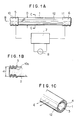
- FIG.1A illustrates a first embodiment of the invention.
- FIG.1B and FIG.1C show a cross-section taken along the line B-B in FIG.1A and a cross section taken along the line C-C, respectively.
- Conductors or electrodes 5,6 are disposed on the outer circumferential surface of a substantially straight glass bulb 1 in the proximity of both ends thereof.
- the glass bulb 1 is charged with mercury vapor and rare gas 2 therein.
- a reflection film 4 On the inner wall of the bulb 1 is provided a reflection film 4 except for a portion 12, forming an aperture through which visible light is emitted.
- a fluophor 3 is applied over the reflection film.
- the glass bulb 1 is provided with circumferential recesses at the end portions 10,11 thereof to form an uneven surface or a plurality of ridges and furrows 10a,11a on which the electrodes 5,6 are configured to these ridges and furrows 10a,11a.
- an inert gas such as argon gas or an inert gas plus a metal vapor.
- a reflection film not shown except for an aperture portion similar to that shown in FIG.2.
- the high frequency generating circuit 7 becomes operative upon the power is turned on as in the prior art and applies a high frequency voltage across the electrodes 5,6 for ionizing the metal vapor in the glass bulb 1 to initiate discharge between the electrodes.
- the metal vapor charged in the glass bulb 1 is excited to emit ultraviolet rays, which in turn causes the fluophor 3 applied on the reflection film to emit the visible light.
- the visible light is emitted to outside of the bulb 1 directly through the aperture 12 of the glass bulb 1 or after being reflected by the reflection film.
- the amount of light emitted depends on the area of the electrodes 5,6 contacting with the bulb.
- the ridges and furrows 10a,11a formed on the end portions of the bulb provide a larger area of the electrodes 5,6 which contacts with the bulb as compared to the prior art lamp where electrodes are provided on a cylindrical end portion of the same diameter as the rest of the bulb.
- this embodiment provides a longer effective length of the glass bulb 1 with the dimension of the electrodes in the longitudinal direction of the bulb 1 being unchanged.
- FIG.3 shows a second embodiment of the invention.
- the diameter of the bulb 1 to which the electrodes 5,6 are disposed is made greater than that of light emitting portion.
- This arrangement can also provide a larger area of the electrodes contacting with the bulb 1 than the bulb having the same diameter over the entire length thereof, thereby providing a longer effective length of the discharge bulb with the dimension of the electrodes in longitudinal direction of the bulb being unchanged.
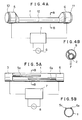
- FIG.4A shows a third embodiment of the invention.
- the end portions 10,11 on which electrodes 5,6 are provided are not coaxial with the portions where light is emitted, so that the surface of the electrodes will be substantially flush with the aperture 12 through which the light is transmitted outwardly.
- FIG.4B is a cross-sectional view taken along the line B-B of FIG.4A, wherein arrows F indicate light transmitted through the aperture 2. This arrangement is particularly useful when the light emitting portion must be positioned very close to an object that requires illumination.
- the end portions 10,11 may have a cross section of rectangular or other non-circular shape.
- the electrodes enclose only the circumferential surface of the end portions of the bulb but instead may enclose the end surface thereof.
- FIG.5A shows a fourth embodiment of the invention and FIG.5B is a cross-sectional view taken along the line B-B of FIG.5A.
- the electrodes 5,6 enclose entire circumferential surface at the end portion of the glass bulb 1 and narrow belt-shaped portions 5a,6a extend longitudinally toward the center of the bulb 1. Short distance between the electrodes 5,6 at a middle portion of the bulb 1 causes a high electric field in the bulb, thus allowing the discharge to take place easily at a low voltage.
- the width of the electrodes 5a,6a at the middle portion of the bulb 1 is narrow and the area thereof is small; therefore a discharge current due to the portions 5a,6a is small which in turn causes only a small amount of light emitted.
- the discharge lamp can provide substantially uniform distribution of light emission across the entire length thereof, being equivalent to the one having the electrodes only at both end portions. This effect can be derived from the shape of the electrodes 5,6, that is simple when manufacturing.
- FIG.6A illustrates a fifth embodiment of the invention and FIG.6B shows a cross-sectional view taken along the line B-B of FIG.6A.
- the narrow belt-shaped portions 5a,6a of the electrodes 5,6 are disposed in parallel to each other in the vicinity of the middle portion of the glass bulb 1. In this manner, varying the lengths of the parallel portions also allows a decrease in discharge-initiating voltage.
- FIG.7A shows a sixth embodiment of the invention and FIG.7B illustrates a cross-section taken along the line B-B of FIG.7A.
- the discharge 8 takes place as shown.
- a high electrode drop is developed at the inner surface of a discharge glass bulb opposite to electrodes mounted on the outer circumferential surface thereof. The electrons and ions, accelerated by this voltage, impinge on the inner wall of the glass bulb, causing damage to the fluophor applied.
- the fluophor 3 applied on the inner surface of the bulb has apertures 9a,9b, diametrically opposite to each other as shown in FIG. 7B and extending longitudinally of the glass bulb.
- electrodes 5,6 On the outer surface of the bulb 1 are provided electrodes 5,6 at locations opposite to the apertures 9a,9b, where the fluophor does not exist.
- the electrodes 5,6 also extend longitudinally of the glass bulb.
- FIG.8A is a vertical cross-sectional view of an eighth embodiment of the invention.
- the fluophor 3 is applied to the inner surface of the glass bulb 1 except for both end portions of the bulb 1 where electrodes 5,6 are provided.
- FIG.8B shows a cross-sectional view taken along the line B-B of FIG.8A and
- FIG.8C illustrates a cross-sectional view taken along the line C-C.
- the high frequency generating circuit 7 applies the high frequency voltage across the electrodes 5,6, thereby initiating the discharge between the electrodes.
Landscapes
- Physics & Mathematics (AREA)
- Electromagnetism (AREA)
- Engineering & Computer Science (AREA)
- Plasma & Fusion (AREA)
- Vessels And Coating Films For Discharge Lamps (AREA)
Applications Claiming Priority (8)
| Application Number | Priority Date | Filing Date | Title |
|---|---|---|---|
| JP34322/88 | 1988-02-17 | ||
| JP3432288A JPH01209654A (ja) | 1988-02-17 | 1988-02-17 | 放電灯 |
| JP5666488A JPH01231260A (ja) | 1988-03-10 | 1988-03-10 | 蛍光ランプ |
| JP56664/88 | 1988-03-10 | ||
| JP13892388A JPH01309249A (ja) | 1988-06-06 | 1988-06-06 | 放電灯 |
| JP138924/88 | 1988-06-06 | ||
| JP138923/88 | 1988-06-06 | ||
| JP63138924A JP2518015B2 (ja) | 1988-06-06 | 1988-06-06 | 放電灯 |
Publications (2)
| Publication Number | Publication Date |
|---|---|
| EP0329143A1 true EP0329143A1 (de) | 1989-08-23 |
| EP0329143B1 EP0329143B1 (de) | 1994-05-04 |
Family
ID=27459912
Family Applications (1)
| Application Number | Title | Priority Date | Filing Date |
|---|---|---|---|
| EP89102691A Expired - Lifetime EP0329143B1 (de) | 1988-02-17 | 1989-02-16 | Entladungslampe |
Country Status (4)
| Country | Link |
|---|---|
| US (1) | US5013966A (de) |
| EP (1) | EP0329143B1 (de) |
| CA (1) | CA1305510C (de) |
| DE (1) | DE68915022T2 (de) |
Cited By (3)
| Publication number | Priority date | Publication date | Assignee | Title |
|---|---|---|---|---|
| EP0497360A3 (de) * | 1991-02-01 | 1994-03-16 | Hughes Aircraft Co | |
| WO1994010701A1 (en) * | 1992-11-02 | 1994-05-11 | Hughes Aircraft Company | Shrouded pin electrode structure for rf excited gas discharge light sources |
| EP2337059A1 (de) * | 2009-12-18 | 2011-06-22 | SICK MAIHAK GmbH | Gasentladungslampe mit Außenelektrode |
Families Citing this family (27)
| Publication number | Priority date | Publication date | Assignee | Title |
|---|---|---|---|---|
| JP3532578B2 (ja) | 1991-05-31 | 2004-05-31 | 三菱電機株式会社 | 放電ランプおよびこれを用いる画像表示装置 |
| JP3075041B2 (ja) * | 1992-12-28 | 2000-08-07 | 三菱電機株式会社 | ガス放電表示装置 |
| US5541475A (en) * | 1993-04-16 | 1996-07-30 | Fusion Lighting, Inc. | Electrodeless lamp with profiled wall thickness |
| US5393979A (en) * | 1993-05-12 | 1995-02-28 | Rae Systems, Inc. | Photo-ionization detector for detecting volatile organic gases |
| US5619103A (en) * | 1993-11-02 | 1997-04-08 | Wisconsin Alumni Research Foundation | Inductively coupled plasma generating devices |
| US5702179A (en) * | 1995-10-02 | 1997-12-30 | Osram Sylvania, Inc. | Discharge lamp having light-transmissive conductive coating for RF containment and heating |
| US5760541A (en) * | 1996-02-26 | 1998-06-02 | Hewlett-Packard Company | Electrode for external electrode fluorescent lamp providing improved longitudinal stability of intensity striations |
| US6191539B1 (en) | 1999-03-26 | 2001-02-20 | Korry Electronics Co | Fluorescent lamp with integral conductive traces for extending low-end luminance and heating the lamp tube |
| DE19915617A1 (de) * | 1999-04-07 | 2000-10-12 | Philips Corp Intellectual Pty | Gasentladungslampe |
| JP2003017005A (ja) * | 2001-06-27 | 2003-01-17 | Harison Toshiba Lighting Corp | 低圧放電ランプ |
| JP2003045337A (ja) * | 2001-07-31 | 2003-02-14 | Fujitsu Ltd | 表示管および表示装置 |
| JP3929265B2 (ja) * | 2001-07-31 | 2007-06-13 | 富士通株式会社 | ガス放電管内への電子放出膜形成方法 |
| EP1415325A1 (de) * | 2001-08-02 | 2004-05-06 | Koninklijke Philips Electronics N.V. | Niederdruckgasentladungslampe |
| JP2003092085A (ja) * | 2001-09-17 | 2003-03-28 | Fujitsu Ltd | 表示装置 |
| KR20030044481A (ko) * | 2001-11-30 | 2003-06-09 | 삼성전자주식회사 | 냉음극선관 방식 램프 및 이를 이용한 액정표시장치 |
| KR100463610B1 (ko) * | 2002-12-31 | 2004-12-29 | 엘지.필립스 엘시디 주식회사 | 백 라이트용 외부전극 형광램프 및 이의 외부전극 형성방법 |
| DE10342337A1 (de) * | 2003-09-11 | 2005-05-04 | Heraeus Noblelight Gmbh | Entladungslampe zur Erzeugung von UV-Strahlung sowie deren Verwendung |
| JP4249689B2 (ja) * | 2003-11-25 | 2009-04-02 | Necライティング株式会社 | 外部電極型放電ランプおよびその製造方法 |
| US20050253523A1 (en) * | 2004-05-14 | 2005-11-17 | Yi-Shiuan Tsai | Fluorescent lamp for backlight device |
| KR100632681B1 (ko) * | 2004-06-30 | 2006-10-12 | 엘지.필립스 엘시디 주식회사 | 외부전극 형광램프 및 그 제조방법 |
| JP2006093083A (ja) * | 2004-08-27 | 2006-04-06 | Masafumi Jinno | 無水銀ランプおよびランプ装置 |
| KR101123454B1 (ko) * | 2004-12-24 | 2012-03-26 | 엘지디스플레이 주식회사 | 형광램프, 그 제조 방법 및 이를 구비한 백라이트 유닛 |
| KR101126485B1 (ko) * | 2005-03-22 | 2012-03-30 | 엘지디스플레이 주식회사 | 램프전극 및 램프전극형성방법 |
| WO2006112127A1 (ja) * | 2005-04-14 | 2006-10-26 | Sharp Kabushiki Kaisha | 放電蛍光管、放電蛍光管の駆動方法、表示装置用照明装置及びこれを備えた表示装置 |
| KR101311676B1 (ko) * | 2005-12-30 | 2013-09-25 | 엘지디스플레이 주식회사 | 램프, 백라이트 유닛 및 이를 이용한 액정표시장치 |
| KR100853808B1 (ko) * | 2007-04-20 | 2008-08-22 | 주식회사 아이노바 | 세라믹-유리질 복합체 전극을 구비한 형광램프 |
| WO2020237438A1 (zh) * | 2019-05-24 | 2020-12-03 | 林文飞 | 紫外线灯管封装的方法及结构 |
Citations (1)
| Publication number | Priority date | Publication date | Assignee | Title |
|---|---|---|---|---|
| DE3723435A1 (de) * | 1986-07-15 | 1988-01-21 | Toshiba Kawasaki Kk | Gasentladungslampe und diese verwendende vorrichtung |
Family Cites Families (9)
| Publication number | Priority date | Publication date | Assignee | Title |
|---|---|---|---|---|
| US702319A (en) * | 1902-01-02 | 1902-06-10 | Daniel Mcfarlan Moore | Electric-tube lamp. |
| US1676790A (en) * | 1922-04-18 | 1928-07-10 | Cooper Hewitt Electric Co | Electric lamp |
| US1612387A (en) * | 1924-11-25 | 1926-12-28 | Raymond R Machlett | Ionic-discharge lamp and process of manufacturing same |
| US1758516A (en) * | 1926-12-11 | 1930-05-13 | Manhattan Electrical Supply Co | Gas-filled tube |
| US2425697A (en) * | 1944-03-02 | 1947-08-12 | Gen Luminescent Corp | Low-temperature luminescent lamp |
| US2624858A (en) * | 1948-11-15 | 1953-01-06 | William B Greenlee | Gaseous discharge lamp |
| US3442582A (en) * | 1966-12-07 | 1969-05-06 | Ibm | Lamp arrangement for document scanning and modified lamp |
| JPS6012660A (ja) * | 1983-07-01 | 1985-01-23 | Mitsubishi Electric Corp | 無声放電式螢光放電管 |
| JPS61185857A (ja) * | 1985-02-13 | 1986-08-19 | Matsushita Electric Works Ltd | 無電極放電灯 |
-
1989
- 1989-02-15 US US07/311,350 patent/US5013966A/en not_active Expired - Lifetime
- 1989-02-16 DE DE68915022T patent/DE68915022T2/de not_active Expired - Fee Related
- 1989-02-16 CA CA000591290A patent/CA1305510C/en not_active Expired - Lifetime
- 1989-02-16 EP EP89102691A patent/EP0329143B1/de not_active Expired - Lifetime
Patent Citations (1)
| Publication number | Priority date | Publication date | Assignee | Title |
|---|---|---|---|---|
| DE3723435A1 (de) * | 1986-07-15 | 1988-01-21 | Toshiba Kawasaki Kk | Gasentladungslampe und diese verwendende vorrichtung |
Non-Patent Citations (3)
| Title |
|---|
| PATENT ABSTRACTS OF JAPAN, Unexamined Applications, E Field, Vol. 11, No. 83, March 13, 1987 The Patent Office Japanese Government page 22 E 489 *Kokai-No. 61-237 361 (Canon)* * |
| PATENT ABSTRACTS OF JAPAN, Unexamined Applications, E Field, Vol. 8, No. 88, April 21, 1984 The Patent Office Japanese Government page 145 E 240 *Kokai-No. 89-9 849 (Okaya Denki Sangyo)* * |
| PATENT ABSTRACTS OF JAPAN, Unexamined Applications, E Field, Vol. 9, No. 126, March 31, 1985 The Patent Office Japanese Government page 1 E 318 *Kokai-No. 60-12 660 (Mitsubishi Denki)* * |
Cited By (3)
| Publication number | Priority date | Publication date | Assignee | Title |
|---|---|---|---|---|
| EP0497360A3 (de) * | 1991-02-01 | 1994-03-16 | Hughes Aircraft Co | |
| WO1994010701A1 (en) * | 1992-11-02 | 1994-05-11 | Hughes Aircraft Company | Shrouded pin electrode structure for rf excited gas discharge light sources |
| EP2337059A1 (de) * | 2009-12-18 | 2011-06-22 | SICK MAIHAK GmbH | Gasentladungslampe mit Außenelektrode |
Also Published As
| Publication number | Publication date |
|---|---|
| CA1305510C (en) | 1992-07-21 |
| DE68915022T2 (de) | 1994-08-18 |
| DE68915022D1 (de) | 1994-06-09 |
| US5013966A (en) | 1991-05-07 |
| EP0329143B1 (de) | 1994-05-04 |
Similar Documents
| Publication | Publication Date | Title |
|---|---|---|
| US5013966A (en) | Discharge lamp with external electrodes | |
| KR900002446B1 (ko) | 불활성 가스 방전등 장치 | |
| EP0460641B1 (de) | Vorrichtung für Edelgas-Fluoreszenzentladungslampen | |
| EP0270004A2 (de) | Gasentladungslampe und diese Lampe benutzendes Gerät | |
| EP0376149B1 (de) | Leuchtstoffentladungslampe mit Edelgas | |
| US5072155A (en) | Rare gas discharge fluorescent lamp device | |
| CA1264063A (en) | Dual cathode beam mode fluorescent lamp with capacitive ballast | |
| JP3346190B2 (ja) | 希ガス放電ランプ | |
| JPH0541202A (ja) | 高周波蛍光システム | |
| JP3576661B2 (ja) | 希ガス放電灯 | |
| JPH06181050A (ja) | 希ガス放電灯装置 | |
| JP2518015B2 (ja) | 放電灯 | |
| EP0378338A2 (de) | Entladungsröhre | |
| JPH06314561A (ja) | 放電ランプ | |
| JPH05190151A (ja) | 原稿照明用放電灯 | |
| EP0577275A1 (de) | Fluoreszenzlampe | |
| JPH05242870A (ja) | 放電ランプ | |
| JPH10116595A (ja) | 無電極放電ランプ | |
| KR100475166B1 (ko) | 램프 | |
| JP3409373B2 (ja) | ソレノイド磁界式放電灯 | |
| JP3139077B2 (ja) | 低圧放電灯 | |
| JPS6244950A (ja) | 無電極放電灯 | |
| JP2004152605A (ja) | 放電ランプ及び液晶バックライト装置 | |
| JPH11297278A (ja) | 希ガス放電灯とその点灯装置 | |
| JPH06163005A (ja) | 希ガス放電灯 |
Legal Events
| Date | Code | Title | Description |
|---|---|---|---|
| PUAI | Public reference made under article 153(3) epc to a published international application that has entered the european phase |
Free format text: ORIGINAL CODE: 0009012 |
|
| AK | Designated contracting states |
Kind code of ref document: A1 Designated state(s): DE FR GB NL |
|
| 17P | Request for examination filed |
Effective date: 19900220 |
|
| 17Q | First examination report despatched |
Effective date: 19920630 |
|
| GRAA | (expected) grant |
Free format text: ORIGINAL CODE: 0009210 |
|
| AK | Designated contracting states |
Kind code of ref document: B1 Designated state(s): DE FR GB NL |
|
| REF | Corresponds to: |
Ref document number: 68915022 Country of ref document: DE Date of ref document: 19940609 |
|
| ET | Fr: translation filed | ||
| PLBE | No opposition filed within time limit |
Free format text: ORIGINAL CODE: 0009261 |
|
| STAA | Information on the status of an ep patent application or granted ep patent |
Free format text: STATUS: NO OPPOSITION FILED WITHIN TIME LIMIT |
|
| 26N | No opposition filed | ||
| REG | Reference to a national code |
Ref country code: GB Ref legal event code: 746 Effective date: 19960611 |
|
| REG | Reference to a national code |
Ref country code: FR Ref legal event code: D6 |
|
| REG | Reference to a national code |
Ref country code: GB Ref legal event code: IF02 |
|
| PGFP | Annual fee paid to national office [announced via postgrant information from national office to epo] |
Ref country code: FR Payment date: 20030210 Year of fee payment: 15 |
|
| PGFP | Annual fee paid to national office [announced via postgrant information from national office to epo] |
Ref country code: GB Payment date: 20030212 Year of fee payment: 15 |
|
| PGFP | Annual fee paid to national office [announced via postgrant information from national office to epo] |
Ref country code: NL Payment date: 20030226 Year of fee payment: 15 |
|
| PGFP | Annual fee paid to national office [announced via postgrant information from national office to epo] |
Ref country code: DE Payment date: 20030227 Year of fee payment: 15 |
|
| PG25 | Lapsed in a contracting state [announced via postgrant information from national office to epo] |
Ref country code: GB Free format text: LAPSE BECAUSE OF NON-PAYMENT OF DUE FEES Effective date: 20040216 |
|
| PG25 | Lapsed in a contracting state [announced via postgrant information from national office to epo] |
Ref country code: NL Free format text: LAPSE BECAUSE OF NON-PAYMENT OF DUE FEES Effective date: 20040901 Ref country code: DE Free format text: LAPSE BECAUSE OF NON-PAYMENT OF DUE FEES Effective date: 20040901 |
|
| GBPC | Gb: european patent ceased through non-payment of renewal fee |
Effective date: 20040216 |
|
| PG25 | Lapsed in a contracting state [announced via postgrant information from national office to epo] |
Ref country code: FR Free format text: LAPSE BECAUSE OF NON-PAYMENT OF DUE FEES Effective date: 20041029 |
|
| NLV4 | Nl: lapsed or anulled due to non-payment of the annual fee |
Effective date: 20040901 |
|
| REG | Reference to a national code |
Ref country code: FR Ref legal event code: ST |