EP0329155B1 - Integrated gas turbine power generation system and process - Google Patents
Integrated gas turbine power generation system and process Download PDFInfo
- Publication number
- EP0329155B1 EP0329155B1 EP89102758A EP89102758A EP0329155B1 EP 0329155 B1 EP0329155 B1 EP 0329155B1 EP 89102758 A EP89102758 A EP 89102758A EP 89102758 A EP89102758 A EP 89102758A EP 0329155 B1 EP0329155 B1 EP 0329155B1
- Authority
- EP
- European Patent Office
- Prior art keywords
- gas turbine
- heat transfer
- gas
- combustion chamber
- air
- Prior art date
- Legal status (The legal status is an assumption and is not a legal conclusion. Google has not performed a legal analysis and makes no representation as to the accuracy of the status listed.)
- Expired - Lifetime
Links
- 238000010248 power generation Methods 0.000 title claims description 21
- 238000000034 method Methods 0.000 title claims description 17
- 230000008569 process Effects 0.000 title description 11
- 239000007789 gas Substances 0.000 claims description 74
- 239000002245 particle Substances 0.000 claims description 58
- 238000002485 combustion reaction Methods 0.000 claims description 50
- 239000007787 solid Substances 0.000 claims description 31
- 238000010438 heat treatment Methods 0.000 claims description 10
- 239000000567 combustion gas Substances 0.000 claims description 6
- 238000005243 fluidization Methods 0.000 claims description 5
- 239000000446 fuel Substances 0.000 claims description 5
- 230000005484 gravity Effects 0.000 claims 2
- 239000003245 coal Substances 0.000 description 8
- 230000001590 oxidative effect Effects 0.000 description 6
- 239000003546 flue gas Substances 0.000 description 5
- 238000011084 recovery Methods 0.000 description 5
- 238000010276 construction Methods 0.000 description 4
- 239000011343 solid material Substances 0.000 description 4
- 239000000725 suspension Substances 0.000 description 4
- UGFAIRIUMAVXCW-UHFFFAOYSA-N Carbon monoxide Chemical compound [O+]#[C-] UGFAIRIUMAVXCW-UHFFFAOYSA-N 0.000 description 2
- 238000005054 agglomeration Methods 0.000 description 2
- 230000002776 aggregation Effects 0.000 description 2
- 239000000919 ceramic Substances 0.000 description 2
- 230000001419 dependent effect Effects 0.000 description 2
- 230000001627 detrimental effect Effects 0.000 description 2
- 239000012530 fluid Substances 0.000 description 2
- 238000004519 manufacturing process Methods 0.000 description 2
- 235000008733 Citrus aurantifolia Nutrition 0.000 description 1
- 235000011941 Tilia x europaea Nutrition 0.000 description 1
- QVGXLLKOCUKJST-UHFFFAOYSA-N atomic oxygen Chemical compound [O] QVGXLLKOCUKJST-UHFFFAOYSA-N 0.000 description 1
- 238000004140 cleaning Methods 0.000 description 1
- 238000005260 corrosion Methods 0.000 description 1
- 230000007797 corrosion Effects 0.000 description 1
- 230000008878 coupling Effects 0.000 description 1
- 238000010168 coupling process Methods 0.000 description 1
- 238000005859 coupling reaction Methods 0.000 description 1
- 229910000514 dolomite Inorganic materials 0.000 description 1
- 239000010459 dolomite Substances 0.000 description 1
- 230000000694 effects Effects 0.000 description 1
- 230000003628 erosive effect Effects 0.000 description 1
- 239000004571 lime Substances 0.000 description 1
- 239000000463 material Substances 0.000 description 1
- 238000002844 melting Methods 0.000 description 1
- 230000008018 melting Effects 0.000 description 1
- 239000002184 metal Substances 0.000 description 1
- 229910001092 metal group alloy Inorganic materials 0.000 description 1
- 239000001301 oxygen Substances 0.000 description 1
- 229910052760 oxygen Inorganic materials 0.000 description 1
- 239000013618 particulate matter Substances 0.000 description 1
- 230000003134 recirculating effect Effects 0.000 description 1
- 238000004064 recycling Methods 0.000 description 1
- 230000009467 reduction Effects 0.000 description 1
- 239000004449 solid propellant Substances 0.000 description 1
- 238000009827 uniform distribution Methods 0.000 description 1
- 239000002918 waste heat Substances 0.000 description 1
Images

Classifications
-
- F—MECHANICAL ENGINEERING; LIGHTING; HEATING; WEAPONS; BLASTING
- F01—MACHINES OR ENGINES IN GENERAL; ENGINE PLANTS IN GENERAL; STEAM ENGINES
- F01D—NON-POSITIVE DISPLACEMENT MACHINES OR ENGINES, e.g. STEAM TURBINES
- F01D15/00—Adaptations of machines or engines for special use; Combinations of engines with devices driven thereby
-
- F—MECHANICAL ENGINEERING; LIGHTING; HEATING; WEAPONS; BLASTING
- F22—STEAM GENERATION
- F22B—METHODS OF STEAM GENERATION; STEAM BOILERS
- F22B31/00—Modifications of boiler construction, or of tube systems, dependent on installation of combustion apparatus; Arrangements or dispositions of combustion apparatus
- F22B31/0007—Modifications of boiler construction, or of tube systems, dependent on installation of combustion apparatus; Arrangements or dispositions of combustion apparatus with combustion in a fluidized bed
- F22B31/0084—Modifications of boiler construction, or of tube systems, dependent on installation of combustion apparatus; Arrangements or dispositions of combustion apparatus with combustion in a fluidized bed with recirculation of separated solids or with cooling of the bed particles outside the combustion bed
-
- F—MECHANICAL ENGINEERING; LIGHTING; HEATING; WEAPONS; BLASTING
- F01—MACHINES OR ENGINES IN GENERAL; ENGINE PLANTS IN GENERAL; STEAM ENGINES
- F01K—STEAM ENGINE PLANTS; STEAM ACCUMULATORS; ENGINE PLANTS NOT OTHERWISE PROVIDED FOR; ENGINES USING SPECIAL WORKING FLUIDS OR CYCLES
- F01K23/00—Plants characterised by more than one engine delivering power external to the plant, the engines being driven by different fluids
- F01K23/02—Plants characterised by more than one engine delivering power external to the plant, the engines being driven by different fluids the engine cycles being thermally coupled
- F01K23/06—Plants characterised by more than one engine delivering power external to the plant, the engines being driven by different fluids the engine cycles being thermally coupled combustion heat from one cycle heating the fluid in another cycle
- F01K23/061—Plants characterised by more than one engine delivering power external to the plant, the engines being driven by different fluids the engine cycles being thermally coupled combustion heat from one cycle heating the fluid in another cycle with combustion in a fluidised bed
-
- Y—GENERAL TAGGING OF NEW TECHNOLOGICAL DEVELOPMENTS; GENERAL TAGGING OF CROSS-SECTIONAL TECHNOLOGIES SPANNING OVER SEVERAL SECTIONS OF THE IPC; TECHNICAL SUBJECTS COVERED BY FORMER USPC CROSS-REFERENCE ART COLLECTIONS [XRACs] AND DIGESTS
- Y02—TECHNOLOGIES OR APPLICATIONS FOR MITIGATION OR ADAPTATION AGAINST CLIMATE CHANGE
- Y02E—REDUCTION OF GREENHOUSE GAS [GHG] EMISSIONS, RELATED TO ENERGY GENERATION, TRANSMISSION OR DISTRIBUTION
- Y02E20/00—Combustion technologies with mitigation potential
- Y02E20/14—Combined heat and power generation [CHP]
-
- Y—GENERAL TAGGING OF NEW TECHNOLOGICAL DEVELOPMENTS; GENERAL TAGGING OF CROSS-SECTIONAL TECHNOLOGIES SPANNING OVER SEVERAL SECTIONS OF THE IPC; TECHNICAL SUBJECTS COVERED BY FORMER USPC CROSS-REFERENCE ART COLLECTIONS [XRACs] AND DIGESTS
- Y02—TECHNOLOGIES OR APPLICATIONS FOR MITIGATION OR ADAPTATION AGAINST CLIMATE CHANGE
- Y02E—REDUCTION OF GREENHOUSE GAS [GHG] EMISSIONS, RELATED TO ENERGY GENERATION, TRANSMISSION OR DISTRIBUTION
- Y02E20/00—Combustion technologies with mitigation potential
- Y02E20/16—Combined cycle power plant [CCPP], or combined cycle gas turbine [CCGT]
Definitions
- This invention relates to an integrated gas turbine power generation system and process respectively according to the preamble of claims 1 and 7. It is more particularly concerned with an integrated power generation system wherein carbonaceous fuel is burned in a non-pressurized circulating fluidized bed combustor to provide heated gas for the gas turbine cycle and steam for the steam turbine cycle.
- An integrated gas turbine power generation system and process is known from GB-A-20 76 062.
- a gas turbine cycle system is provided including a gas compressor, a heat transfer means for heating the compressed gas, and a gas turbine for expanding the compressed gas, connected through the heat transfer means to the gas compressor, the heat transfer means including heat exchange passages disposed inside the channel in the circulating fluidized bed system.
- One embodiment shows a heating bed including a fluidized bed of particles, the bed being connected to the lower end of the particle separator in the vertical channel.
- the separated particles are collected in the fluidized bed and heat transfer tubes are disposed both above and in the bed for the heat exchange to take place.
- relatively large amounts of fluidizing air are required to maintain the particles in the fluidized state.
- the amount of additional fluidized air is dependent upon the amount of particles being recycled and cannot be adjusted according to the needs of the combustion process for the varying loads of the power plant.
- it is important in the power plant to be able to control all parameters effecting the combustion, and especially to control the air feeding systems.
- a typical integrated power plant system includes a pressurized coal combustion system.
- a compressor provides pressurized air, 6-30 bar, into the combustor.
- the gas produced in the combustor is cleaned and employed to drive an expansion turbine.
- a waste heat boiler can be arranged for heat recovery after the turbine.
- the combuster includes a conventional steam generator to produce steam for driving a steam turbine electrical generator assembly.
- the integrated power plants including pressurized coal combustion systems require an expensive and complicated construction.
- the coal feeding system is not easily arranged.
- the use of gas turbines is limited by the inability of the gas turbines to accept effluents from lower graded fuels.
- the high temperature effluents require complicated clean-up systems which increase costs.
- the turbine blades erode and foul as they are exposed to particulate matter not separated in the clean-up system.
- U.S. Patent No. 4,326,373 discloses an atmospheric coal combustion process in which the heat generated is recovered by air compressed in a hydraulic compressor and passed through air heaters (2) in the flue gas passage above the combustion chamber and through air heaters (4 in Figure 1, U.S. Patent No. 4,326,373) in the combustion chamber.
- the compressed and heated air is used for the production of work in a gas turbine.
- a heat exchanger (4) is exposed to extremely high corrosion/erosion.
- a heat exchanger (2) will be large and expensive due to inefficient heat transfer between flue gases and preheated air inside the tubes. Heat exchange rates between suspensions and tubes inserted in the suspension are dependent on the particle density of the suspension. In a fluidized bed, there are great variations in heat exchange at different heights in a fluidized bed combustion chamber. Maximum heat exchange can be achieved only in the lower part of the combustion chamber, in the dense zone of the bed.
- the air heat recovery arrangements in the combustor can also easily cause disturbances in the combustion process and the overall process will be difficult to control.
- the temperature profile in the combustor will be affected by these extra heat exchange tubes disposed in the reactor. And furthermore as there already are heat transfer tubes for steam generation arranged in the reactor, it can be difficult to fit in any other tubes.
- U.S. Patent No. 4,406,128 discloses a combined cycle power plant utilizing a gas turbine for generating electric power. Carbonaceous fuel is burned in a non-pressurized fluidized bed combustor to provide energy for driving the gas turbine and generating steam. An external heat transfer unit through which a portion of the hot solids of the fluidized bed is circulated is used to heat clean compressed air. The heated compressed air is expanded in a gas turbine for the generation of electric power in a generator coupled thereto.
- the external heat transfer unit consists of an air heater chamber with inserted parallel tubes. A portion of hot solid particles from the fluidized bed is conveyed through these tubes with the aid of some fluidizing air. The clean compressed air passes into the air heater and around the outside surfaces of the tubes, extracting heat from them.
- WO 82/00701 discloses a power generation plant with a recirculating fluidized bed furnace operating at a fluidization velocity of 10 m/s and delivering combustion products to a separating section.
- the solid particles from the separating section are led through a weir chamber to a second shallow fluidized bed.
- An air heater is disposed in the second fluidized bed space as well as tubes for steam generation, both tubes in different parts of the bed.
- the bed is operating at a lower fluidization velocity than the bed in the furnace, i.e. 0.5 m/s.
- the heated compressed air is supplied partly to a coal devolatilizer in the power generation system and partly to a burner which is connected to a gas turbine for generation of electrical power.
- This system has the same drawbacks as the previous one, the construction with a second fluidized bed is space-consuming and expensive.
- the additional air needed in the system to fluidize the second fluidized bed is a drawback and makes it more difficult to control the combustion process and hence the whole system.
- Compressed air needed to fluidize the bed is of course a cost in itself.
- an integrated gas turbine power generation system comprising a circulating fluidized bed combustor for the combustion of carbonaceous fuel at nearly an atmospheric pressure, and steam and gas turbine cycles.
- the combustor includes a combustion chamber section, a solid particle separator and a vertical return channel for conveying separated solid particles from the particle separator to the combustion chamber.
- the vertical return channel is connected with its upper end to the lower part of the particle separator and with its lower end to the inlet for solid recycled particles in the combustion chamber.
- the gas turbine cycle includes a gas compressor for compressing a flow of oxidizing gas, a heat transfer means connected through a duct to the compressor for heating the flow of compressed oxidizing gas, a gas expansion turbine connected through a second duct to the heat transfer means for power generation from the heated compressed oxidizing gas, and a third duct for leading expanded oxidizing gas from the gas turbine to the bottom of the combustion chamber.
- the heat transfer means for heating oxidizing gas includes heat exchange passages or tubes disposed inside the vertical return channel for leading compressed gas inside the passages or tubes in indirect contact with a relatively dense suspension of separated particles flowing evenly downwards outside the passages or tubes from the upper part of the channel to the lower part thereof. A process for generating power in such an integrated power system is also disclosed.
- the present invention offers a compact circulating fluidized bed combustor with an air heater integrated into the circulation of solid material.
- the heat exchange passages or tubes are disposed in the vertical return channel where the solids density and consequently heat exchange rate is high. Due to high heat transfer rates, the heat exchanger can be built compact. Heat exchange in the vertical channel is uniform. By leading the solid material through the channel by gravitation, no auxiliary fluidizing air is needed differently from prior art fluidized heat exchangers. Therefore, the present invention offers a more uniform heat transfer process throughout the whole heat exchanger, without temperature profiles as in fluidized heat exchangers. The overall efficiency is increased when no pressurized gas/air is needed for the fluidization of hot particles. Besides production costs, fluidized air can have detrimental effects on hot particles such as burning or agglomeration of particles.
- the invention makes it possible to control the temperature in the combustion chamber by controlling the temperature of recycled hot particles.
- the heat transfer from the hot particles in the vertical channel to the compressed air is affected by changes in the air flow or air pressure.
- the major advantages of the invention compared with the conventional cogeneration system are higher power efficiency and potential to controlling the combustion temperature by extracting energy from the recirculation loop as the air used as working fluid in the gas turbine process also acts as combustion air in the boiler.
- the air flow rate should be controlled to correspond to the boiler load, i.e., 30-100%.
- the utilization of air as working fluid in the gas turbine process is simple and reliable, no gas cleaning is needed.
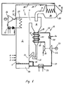
- FIG. 1 A preferred embodiment of the present invention is shown in Figure 1, where carbonaceous solid material is combusted in a circulating fluidized bed combustor 1.
- the combustor includes a combustion chamber 2 with inlets 3, 4 for solid fuel material and eventual other solid materials such as lime or dolomite for the reduction of SO2 in the flue gases.
- the fluidizing air and oxidizing air is led into the combustion chamber through a bottom plate 5 with openings for the air.
- the air is led into the reactor at nearly an atmospheric pressure at a flow rate high enough to fluidize the bed and entrain a portion of the solid particles. Secondary air can be led into the combustion chamber through an inlet 6 above the bottom plate.
- the combustion chamber has an outlet 7 for combustion gases containing entrained solid particles.
- the combustion gases are led to a cyclone separator 8 where the solid particles are separated from the gases.
- the cleaned gas is discharged through an outlet pipe 9 and the solid particles are led downwards through a vertical channel 10 back into the combustion chamber.
- the channel forms a bend 11 at its lower end in front of the inlet 13 to the combustion chamber.
- a steam turbine cycle 14 is integrated with the combustion chamber.
- heat transfer means 15 for steam generation are disposed inside the combustion chamber.
- a steam turbine 16 is connected to the heat transfer tubes for power generation.
- the steam is condensed in a heat recovery condensor 17 and circulated back into the heat transfer tubes in the combustion chamber with a high pressure pump.
- a gas turbine cycle 18 is integrated with the circulating fluidized bed system. Air is compressed in a compressor 19 to about 5-15 bar and led through a first duct 20 into a second heat transfer means 21 in the vertical channel 10, where the air is heated to 500-900°C, preferably to 650-850°C. The solids density in the vertical channel is about 50-1000 kg/m3 which gives a very good heat transfer rate. From the heat exchanger 21, the compressed and heated air is led to a gas turbine 23 through a duct 22. The air is expanded and produces electrical power through a generator 24. An additional heater 25 can be used to increase the temperature of the gas to 1000-1100°C. The heater can be a burner using oil or gas 26.
- the expanded clean air is led through a third duct 27 mainly into an air chamber 28 under the bottom plate 5 in the combustion chamber 2.
- the temperature of the air is about 300-450°C if no additional heater is used and about 500-650°C if the additional heater is used to heat air before the turbine. If the temperature of the expanded air is too high, a heat exchanger 29 can be connected to the third duct. It is also possible to lead the hot air from the gas turbine to a location 30 above the bottom plate.
- the heat exchanger 21 preferably consists of bent ceramic tubes 31 which have a good heat transfer rate and are resistant even in high temperature applications.
- tubes of resistant metal alloys can be used as well.
- the tubes have preferably a diameter of 50-200 mm.
- the tubes 31 are preferably disposed horizontally in the channel 10 and are connected to each other and to the first and second ducts 20, 22 through connecting means outside the channel 10.
- Straight tubes can be used if metal couplings outside the channel are used to connect the tubes to each other. In some applications, vertically disposed tubes could be used as well.
- the air passages in the heat exchanger 21 are preferably tubes but channels between e.g., ceramic plates could be used as well for heat exchange between air and solid particles.
- the cleaned gases discharged through outlet pipe 9 are passed to a heat recovery boiler 32.
- a heat exchanger 33 in the recovery boiler is connected to the steam turbine cycle 14 through ducts 34 and 35.
- the cleaned and cooled gas is discharged to stack through duct 36.
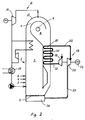
- a second embodiment is shown in Figure 2.
- the same reference numbers are used as in Figure 1.
- a horizontal cyclone 8 is used instead of a vertical cyclone to separate solid particles from the combustion gases. This enables a combustor design which is even more compact than what is shown in Figure 1.
- the first heat transfer means 15 consists of tubewalls in the combustion chamber connected to the steam cycle.
- Tests have been performed to calculate thermal efficiencies in power generation systems according to the invention.
- Polish coal with a low heating value of 28,800 kJ/kg/d.s. was burned in the combustor.
- the air inlet temperature was 15°C and the flue gas outlet temperature was 120°C. Air flow was 98.2 kg/s.
- the polytropic efficiency of the compressor used was 0.9 and of the gas turbine 0.8.
- Pressure drop over the heat exchanger was 0.02 bar and over the combustion chamber 0.1 bar. 44.06% of the heat transferred to steam was converted to steam turbine power.
- the thermal efficiency is clearly increasing when the temperature of air is increased due to indirect heating with hot recycling particles in the vertical return channel.
Landscapes
- Engineering & Computer Science (AREA)
- Chemical & Material Sciences (AREA)
- Combustion & Propulsion (AREA)
- Mechanical Engineering (AREA)
- General Engineering & Computer Science (AREA)
- Physics & Mathematics (AREA)
- Thermal Sciences (AREA)
- Fluidized-Bed Combustion And Resonant Combustion (AREA)
- Engine Equipment That Uses Special Cycles (AREA)
Applications Claiming Priority (2)
| Application Number | Priority Date | Filing Date | Title |
|---|---|---|---|
| US07/157,015 US4827723A (en) | 1988-02-18 | 1988-02-18 | Integrated gas turbine power generation system and process |
| US157015 | 1988-02-18 |
Publications (2)
| Publication Number | Publication Date |
|---|---|
| EP0329155A1 EP0329155A1 (en) | 1989-08-23 |
| EP0329155B1 true EP0329155B1 (en) | 1993-12-08 |
Family
ID=22562022
Family Applications (1)
| Application Number | Title | Priority Date | Filing Date |
|---|---|---|---|
| EP89102758A Expired - Lifetime EP0329155B1 (en) | 1988-02-18 | 1989-02-17 | Integrated gas turbine power generation system and process |
Country Status (6)
| Country | Link |
|---|---|
| US (1) | US4827723A (2) |
| EP (1) | EP0329155B1 (2) |
| JP (1) | JPH01310126A (2) |
| KR (1) | KR910009058B1 (2) |
| DE (2) | DE68911165T2 (2) |
| ES (1) | ES2048774T3 (2) |
Families Citing this family (27)
| Publication number | Priority date | Publication date | Assignee | Title |
|---|---|---|---|---|
| JP2637449B2 (ja) * | 1988-01-12 | 1997-08-06 | 三菱重工業株式会社 | 流動床燃焼方法 |
| US4864969A (en) * | 1988-08-05 | 1989-09-12 | The Babcock & Wilcox Company | Pressurized fluid bed hot gas depressurization system |
| SE466814B (sv) * | 1989-06-01 | 1992-04-06 | Kvaerner Generator Ab | Anordning foer nedbrytande av gaser alstrade vid foerbraenning vid ungefaer 850 grader c av fasta braenslen i en fluidbaedd |
| DE4040699A1 (de) * | 1990-04-27 | 1991-10-31 | Siemens Ag | Kombinierte gas- und dampf-turbinenanlage |
| US5324421A (en) * | 1990-10-04 | 1994-06-28 | Phillips Petroleum Company | Method of protecting heat exchange coils in a fluid catalytic cracking unit |
| US5218931A (en) * | 1991-11-15 | 1993-06-15 | Foster Wheeler Energy Corporation | Fluidized bed steam reactor including two horizontal cyclone separators and an integral recycle heat exchanger |
| US5255507A (en) * | 1992-05-04 | 1993-10-26 | Ahlstrom Pyropower Corporation | Combined cycle power plant incorporating atmospheric circulating fluidized bed boiler and gasifier |
| US5239946A (en) * | 1992-06-08 | 1993-08-31 | Foster Wheeler Energy Corporation | Fluidized bed reactor system and method having a heat exchanger |
| CA2102637A1 (en) * | 1992-11-13 | 1994-05-14 | David H. Dietz | Circulating fluidized bed reactor combined cycle power generation system |
| US5347954A (en) * | 1993-07-06 | 1994-09-20 | Foster Wheeler Energy Corporation | Fluidized bed combustion system having an improved pressure seal |
| US5544479A (en) * | 1994-02-10 | 1996-08-13 | Longmark Power International, Inc. | Dual brayton-cycle gas turbine power plant utilizing a circulating pressurized fluidized bed combustor |
| US5537941A (en) * | 1994-04-28 | 1996-07-23 | Foster Wheeler Energy Corporation | Pressurized fluidized bed combustion system and method with integral recycle heat exchanger |
| US5471955A (en) * | 1994-05-02 | 1995-12-05 | Foster Wheeler Energy Corporation | Fluidized bed combustion system having a heat exchanger in the upper furnace |
| US5735682A (en) * | 1994-08-11 | 1998-04-07 | Foster Wheeler Energy Corporation | Fluidized bed combustion system having an improved loop seal valve |
| SE9601393L (sv) * | 1996-04-12 | 1997-10-13 | Abb Carbon Ab | Förfarande för förbränning och förbränningsanläggning |
| US5809912A (en) * | 1996-06-11 | 1998-09-22 | Foster Wheeler Energy, Inc. | Heat exchanger and a combustion system and method utilizing same |
| ES2154572B1 (es) * | 1998-11-05 | 2001-10-01 | Dalering Desarrollos Energetic | Sistema con ciclo abierto de turbina de gas de combustion externa. |
| FR2914011A1 (fr) * | 2007-03-23 | 2008-09-26 | Joseph Haiun | Centrale electrique a pression atmospherique |
| SE535434C2 (sv) * | 2010-12-15 | 2012-08-07 | Redian Ab | Indirekt eldat gasturbinsystem |
| ES2547810T3 (es) * | 2012-11-23 | 2015-10-08 | Alstom Technology Ltd. | Caldera que comprende un intercambiador de calor de lecho fluidizado |
| KR20180029957A (ko) | 2015-04-17 | 2018-03-21 | 노스트럼 에너지 피티이. 리미티드 | 신규 다중루프 가스 터빈 및 그 작동 방법 |
| GB2547927B (en) * | 2016-03-03 | 2018-05-23 | Rolls Royce Plc | Supercritical fluid heat engine |
| US10443495B2 (en) | 2017-04-14 | 2019-10-15 | Enexor Energy | Combined heat and power system and method of operation |
| US11507073B2 (en) * | 2017-10-24 | 2022-11-22 | Mitsubishi Heavy Industries, Ltd. | State display device for plant and state display method for plant |
| FI129147B (en) * | 2017-12-19 | 2021-08-13 | Valmet Technologies Oy | Fluidized bed boiler with gas lock heat exchanger |
| EP4001613B1 (en) | 2020-11-23 | 2024-06-19 | The Boeing Company | Methods and systems for generating power and thermal management having dual loop architecture |
| EP4001599B8 (en) * | 2020-11-23 | 2023-04-12 | The Boeing Company | Methods and systems for generating power and thermal management having combined cycle architecture |
Family Cites Families (11)
| Publication number | Priority date | Publication date | Assignee | Title |
|---|---|---|---|---|
| US3677008A (en) * | 1971-02-12 | 1972-07-18 | Gulf Oil Corp | Energy storage system and method |
| US4312301A (en) * | 1980-01-18 | 1982-01-26 | Battelle Development Corporation | Controlling steam temperature to turbines |
| GB2076062B (en) * | 1980-05-16 | 1984-04-26 | English Electric Co Ltd | Turbine power plant |
| US4369624A (en) * | 1981-01-02 | 1983-01-25 | Westinghouse Electric Corp. | High temperature gas turbine systems |
| US4406128A (en) * | 1981-11-13 | 1983-09-27 | Struthers-Wells Corporation | Combined cycle power plant with circulating fluidized bed heat transfer |
| US4479355A (en) * | 1983-02-25 | 1984-10-30 | Exxon Research & Engineering Co. | Power plant integrating coal-fired steam boiler with air turbine |
| US4503681A (en) * | 1983-07-14 | 1985-03-12 | General Electric Company | State-of-the-art gas turbine and steam turbine power plant |
| SE8500750L (sv) * | 1985-02-18 | 1986-08-19 | Asea Stal Ab | Kraftanleggning for forbrenning av partikulert brensle i fluidiserad bedd |
| FI853464A0 (fi) * | 1985-09-11 | 1985-09-11 | Ahlstroem Oy | Reaktor med cirkulerande baedd. |
| DE3613300A1 (de) * | 1986-04-19 | 1987-10-22 | Bbc Brown Boveri & Cie | Verfahren zum erzeugen von elektrischer energie mit einer eine wirbelschichtfeuerung aufweisenden kombinierten gasturbinen-dampfkraftanlage sowie anlage zur durchfuehrung des verfahrens |
| US4709663A (en) * | 1986-12-09 | 1987-12-01 | Riley Stoker Corporation | Flow control device for solid particulate material |
-
1988
- 1988-02-18 US US07/157,015 patent/US4827723A/en not_active Expired - Fee Related
-
1989
- 1989-02-17 KR KR1019890001891A patent/KR910009058B1/ko not_active Expired
- 1989-02-17 DE DE89102758T patent/DE68911165T2/de not_active Expired - Fee Related
- 1989-02-17 EP EP89102758A patent/EP0329155B1/en not_active Expired - Lifetime
- 1989-02-17 JP JP1036450A patent/JPH01310126A/ja active Granted
- 1989-02-17 ES ES89102758T patent/ES2048774T3/es not_active Expired - Lifetime
- 1989-02-17 DE DE198989102758T patent/DE329155T1/de active Pending
Also Published As
| Publication number | Publication date |
|---|---|
| ES2048774T3 (es) | 1994-04-01 |
| US4827723A (en) | 1989-05-09 |
| KR890013312A (ko) | 1989-09-22 |
| KR910009058B1 (ko) | 1991-10-28 |
| DE68911165D1 (de) | 1994-01-20 |
| DE329155T1 (de) | 1990-02-08 |
| JPH01310126A (ja) | 1989-12-14 |
| DE68911165T2 (de) | 1994-05-11 |
| EP0329155A1 (en) | 1989-08-23 |
| JPH0584820B2 (2) | 1993-12-03 |
Similar Documents
| Publication | Publication Date | Title |
|---|---|---|
| EP0329155B1 (en) | Integrated gas turbine power generation system and process | |
| EP0680548B1 (en) | Combined cycle power plant incorporating atmospheric circulating fluidized bed boiler and gasifier | |
| US4116005A (en) | Combined cycle power plant with atmospheric fluidized bed combustor | |
| US4470255A (en) | Power generation plant | |
| CN1051362C (zh) | 燃烧煤热解气和焦炭的多级炉和产生动力的方法 | |
| US4253300A (en) | Supplementary fired combined cycle power plants | |
| CA2148920C (en) | Method and apparatus for operating a circulating fluidized bed system | |
| US4468923A (en) | Process and plant for generating electrical energy | |
| SU898960A3 (ru) | Способ сжигани твердого углеродосодержащего топлива в кип щем слое | |
| EP0278609B1 (en) | Gas turbine power plant fired by a water-bearing fuel | |
| US5236354A (en) | Power plant with efficient emission control for obtaining high turbine inlet temperature | |
| CN1014925B (zh) | 正压流化床燃烧(pfbc)发电设备 | |
| US4326373A (en) | Integrated gas turbine power generation system and process | |
| US5469698A (en) | Pressurized circulating fluidized bed reactor combined cycle power generation system | |
| CA2094205C (en) | Fluidized bed water pipe boiler divided type | |
| JP3093775B2 (ja) | ガスタービン・蒸気タービン複合サイクル方式と該方式の実施に使用する発電設備 | |
| JPS63220008A (ja) | 蒸気発生装置及びその運転方法 | |
| CA1180197A (en) | Combined cycle power plant with circulating fluidized bed heat transfer | |
| JPH10506983A (ja) | 循環式流動床反応器を有する組合わせサイクル発電設備 | |
| CN212618218U (zh) | 大容量循环流化床锅炉 | |
| CN214307064U (zh) | 一种660mw等级高效超超临界循环流化床锅炉 | |
| Balasubramanian et al. | An insight into advance technology in circulating fluidised bed combustion steam generators | |
| CN121498049A (zh) | 一种循环流化床锅炉变负荷调峰系统 | |
| CA1313088C (en) | Steam generator and method of operating same utilizing separate fluid and combined gas flow circuits | |
| CN117553294A (zh) | 一种基于动势能转化的空间自由流化燃烧锅炉结构 |
Legal Events
| Date | Code | Title | Description |
|---|---|---|---|
| PUAI | Public reference made under article 153(3) epc to a published international application that has entered the european phase |
Free format text: ORIGINAL CODE: 0009012 |
|
| 17P | Request for examination filed |
Effective date: 19890217 |
|
| AK | Designated contracting states |
Kind code of ref document: A1 Designated state(s): DE ES FR GB IT |
|
| EL | Fr: translation of claims filed | ||
| DET | De: translation of patent claims | ||
| 17Q | First examination report despatched |
Effective date: 19910305 |
|
| GRAA | (expected) grant |
Free format text: ORIGINAL CODE: 0009210 |
|
| AK | Designated contracting states |
Kind code of ref document: B1 Designated state(s): DE ES FR GB IT |
|
| PG25 | Lapsed in a contracting state [announced via postgrant information from national office to epo] |
Ref country code: IT Free format text: LAPSE BECAUSE OF FAILURE TO SUBMIT A TRANSLATION OF THE DESCRIPTION OR TO PAY THE FEE WITHIN THE PRESCRIBED TIME-LIMIT;WARNING: LAPSES OF ITALIAN PATENTS WITH EFFECTIVE DATE BEFORE 2007 MAY HAVE OCCURRED AT ANY TIME BEFORE 2007. THE CORRECT EFFECTIVE DATE MAY BE DIFFERENT FROM THE ONE RECORDED. Effective date: 19931208 |
|
| REF | Corresponds to: |
Ref document number: 68911165 Country of ref document: DE Date of ref document: 19940120 |
|
| ET | Fr: translation filed | ||
| REG | Reference to a national code |
Ref country code: ES Ref legal event code: FG2A Ref document number: 2048774 Country of ref document: ES Kind code of ref document: T3 |
|
| PLBE | No opposition filed within time limit |
Free format text: ORIGINAL CODE: 0009261 |
|
| STAA | Information on the status of an ep patent application or granted ep patent |
Free format text: STATUS: NO OPPOSITION FILED WITHIN TIME LIMIT |
|
| 26N | No opposition filed | ||
| REG | Reference to a national code |
Ref country code: FR Ref legal event code: TP |
|
| REG | Reference to a national code |
Ref country code: GB Ref legal event code: 732E |
|
| REG | Reference to a national code |
Ref country code: ES Ref legal event code: PC2A Owner name: FOSTER WHEELER ENERGIA OY |
|
| PGFP | Annual fee paid to national office [announced via postgrant information from national office to epo] |
Ref country code: FR Payment date: 20000112 Year of fee payment: 12 |
|
| PGFP | Annual fee paid to national office [announced via postgrant information from national office to epo] |
Ref country code: GB Payment date: 20000120 Year of fee payment: 12 |
|
| PGFP | Annual fee paid to national office [announced via postgrant information from national office to epo] |
Ref country code: DE Payment date: 20000127 Year of fee payment: 12 |
|
| PGFP | Annual fee paid to national office [announced via postgrant information from national office to epo] |
Ref country code: ES Payment date: 20000208 Year of fee payment: 12 |
|
| PG25 | Lapsed in a contracting state [announced via postgrant information from national office to epo] |
Ref country code: GB Free format text: LAPSE BECAUSE OF NON-PAYMENT OF DUE FEES Effective date: 20010217 |
|
| PG25 | Lapsed in a contracting state [announced via postgrant information from national office to epo] |
Ref country code: ES Free format text: LAPSE BECAUSE OF NON-PAYMENT OF DUE FEES Effective date: 20010219 |
|
| GBPC | Gb: european patent ceased through non-payment of renewal fee |
Effective date: 20010217 |
|
| PG25 | Lapsed in a contracting state [announced via postgrant information from national office to epo] |
Ref country code: FR Free format text: LAPSE BECAUSE OF NON-PAYMENT OF DUE FEES Effective date: 20011031 |
|
| REG | Reference to a national code |
Ref country code: FR Ref legal event code: ST |
|
| PG25 | Lapsed in a contracting state [announced via postgrant information from national office to epo] |
Ref country code: DE Free format text: LAPSE BECAUSE OF NON-PAYMENT OF DUE FEES Effective date: 20011201 |
|
| REG | Reference to a national code |
Ref country code: ES Ref legal event code: FD2A Effective date: 20020916 |