EP0329343A2 - Getriebesystem für ein vierradgetriebenes Fahrzeug - Google Patents
Getriebesystem für ein vierradgetriebenes Fahrzeug Download PDFInfo
- Publication number
- EP0329343A2 EP0329343A2 EP89301285A EP89301285A EP0329343A2 EP 0329343 A2 EP0329343 A2 EP 0329343A2 EP 89301285 A EP89301285 A EP 89301285A EP 89301285 A EP89301285 A EP 89301285A EP 0329343 A2 EP0329343 A2 EP 0329343A2
- Authority
- EP
- European Patent Office
- Prior art keywords
- transmission
- drive
- output shaft
- wheel drive
- oil
- Prior art date
- Legal status (The legal status is an assumption and is not a legal conclusion. Google has not performed a legal analysis and makes no representation as to the accuracy of the status listed.)
- Granted
Links
- 230000005540 biological transmission Effects 0.000 title claims abstract description 52
- 239000012530 fluid Substances 0.000 claims abstract description 11
- 239000003921 oil Substances 0.000 description 53
- 239000010687 lubricating oil Substances 0.000 description 3
- 230000001050 lubricating effect Effects 0.000 description 2
- 238000005192 partition Methods 0.000 description 2
- 230000004075 alteration Effects 0.000 description 1
- XAGFODPZIPBFFR-UHFFFAOYSA-N aluminium Chemical compound [Al] XAGFODPZIPBFFR-UHFFFAOYSA-N 0.000 description 1
- 229910052782 aluminium Inorganic materials 0.000 description 1
- 230000009194 climbing Effects 0.000 description 1
- 238000004512 die casting Methods 0.000 description 1
- 239000000446 fuel Substances 0.000 description 1
- 125000006850 spacer group Chemical group 0.000 description 1
- 238000003466 welding Methods 0.000 description 1
Images


Classifications
-
- B—PERFORMING OPERATIONS; TRANSPORTING
- B60—VEHICLES IN GENERAL
- B60K—ARRANGEMENT OR MOUNTING OF PROPULSION UNITS OR OF TRANSMISSIONS IN VEHICLES; ARRANGEMENT OR MOUNTING OF PLURAL DIVERSE PRIME-MOVERS IN VEHICLES; AUXILIARY DRIVES FOR VEHICLES; INSTRUMENTATION OR DASHBOARDS FOR VEHICLES; ARRANGEMENTS IN CONNECTION WITH COOLING, AIR INTAKE, GAS EXHAUST OR FUEL SUPPLY OF PROPULSION UNITS IN VEHICLES
- B60K17/00—Arrangement or mounting of transmissions in vehicles
- B60K17/34—Arrangement or mounting of transmissions in vehicles for driving both front and rear wheels, e.g. four wheel drive vehicles
- B60K17/348—Arrangement or mounting of transmissions in vehicles for driving both front and rear wheels, e.g. four wheel drive vehicles having differential means for driving one set of wheels, e.g. the front, at one speed and the other set, e.g. the rear, at a different speed
- B60K17/35—Arrangement or mounting of transmissions in vehicles for driving both front and rear wheels, e.g. four wheel drive vehicles having differential means for driving one set of wheels, e.g. the front, at one speed and the other set, e.g. the rear, at a different speed including arrangements for suppressing or influencing the power transfer, e.g. viscous clutches
Definitions
- the present invention relates to a power transmission system for a four-wheel drive motor vehicle, and more particularly to a system having a fluid operated multiple-disk friction clutch.
- This type of clutch is employed in a transfer device for distributing the output torque of a transmission to auxiliary drive wheels.
- the power transmission system can be converted from a two-wheel drive system to a four-wheel drive system by engaging the clutch.
- the front axle load is larger than the rear axle load.
- the rear axle load may be greatest.
- the engine power is directly transmitted to the front wheels or the rear wheels in accordance with the layout of the drive line and the distribution of the axle load of the four-wheel drive motor vehicle, thereby improving driveability, driving stability and fuel consumption.
- Japanese Patent Application Laid-Open 62-143720 discloses a four-wheel drive layout where a transmission output shaft is connected to rear drive wheels and a fluid operated friction clutch is provided on the out put shaft. The engine power from the clutch is transmitted to the front wheels through a pair of gears, a shaft provided outside the transmission and a front differential.
- Japanese Patent Application Laid-Open 62-23823 discloses a four-wheel drive motor vehicle in which the engine power is derived from a fluid operated friction clutch provided on a transmission output shaft through sprocket wheels and chains.
- the four-wheel drive motor vehicle having the front-mounted engine with rear-wheel drive layout is constructed on the basis of the two-wheel drive motor vehicle having the front-mounted engine with rear-wheels drive layout, it is difficult to alter the system to a front-wheel drive four-wheel system.
- the object of the present invention is to provide a power transmission system for a four-wheel drive motor vehicle in which a transfer system can be easily altered between the front-wheel drive based four-wheel drive system and the rear-wheel drive based four-wheel drive system.
- a power transmission system for a four-wheel drive motor vehicle comprising a transmission for transmitting power from an engine, a transfer device for distributing the output from an output shaft of the transmission to a front and/or rear power train, to the front power train for transmitting the output of the transfer device to the front wheels, and the rear power train for transmitting the output of the transfer device to the rear wheels, characterised in that the transfer device consists of: a drive gear rotatably mounted on the output shaft of the transmission and engaged with a gear in one of the power trains, a hydraulic clutch having a first drum engageable with a second drum, the first drum being secured to the drive gear and the second drum being secured to a member of a one of the power trains;and the output shaft of the transmission, and the drive gear being arranged to be replaced with an output shaft engaged with a drive gear for the front power train.
- the transmission is an automatic transmission
- the fluid operated clutch is a fluid operated multiple-disk friction clutch.
- FIGs. 1a and 1b are sectional views showing a power transmission system for a rear-wheel drive based four-wheel drive motor vehicle having a front-mounted engine according to the present invention
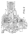
- Fig. 2 is an enlarged sectional view showing a part of the system of Fig. 1;
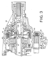
- Fig. 3 is a sectional view showing a part of system for having a front-wheel drive based four-wheel drive vehicie.
- Figs. 1a and 1b show a power transmission system in a transaxle type for a rear-wheel drive based four-wheel drive motor vehicle having an engine at a front portion thereof.
- the power transmission system has a differential case 1 made of die casting aluminum, a torque converter 4 with a lockup clutch 3 mounted in a converter box 2, and a differential 6 mounted in a differential box 5 behind the torque converter 4.
- the differential case 1 has a cylindrical portion 1a, and a lower partition 1b and an inclined partition 1c which define a front side compartment and a rear side compartment.
- a shaft supporting plate 8 having a pump housing 7 is attached to the rear end of the differential case 1.
- An oil pump 10 is housed in the pump housing 7 and a cover 9.
- a transmission case 11 housing an automatic transmission 12 is attached to the rear of the shaft supporting plate 8.
- a crankshaft 20 of the engine E has a boss 20a to which a drive plate 21 is fixed by bolts 22.
- a converter cover 23 is secured to the drive plate 21 by bolts 24 at a flange 23a.
- the torque converter 4 comprises an impeller 25 integral with the converter cover 23 by welding, a turbine 26 and a stator 27 connected to a hollow stator shaft 32 through a one-way clutch 31.
- the turbine 26 is fixed by rivets 30 to a disc having a turbine hub 29 which is splined to an input shaft 28 disposed in the stator shaft 32.
- the input shaft 28 extends into the transmission case 11.
- the stator shaft 32 is integral with the cover 9 of the oil pump 10.
- a pump drive shaft 33 surrounding the stator shaft 32 is connected to the impeller 25 and is operatively connected with a rotor of the oil pump 10.
- a seal pipe 34 for covering the pump drive shaft 33 is further provided.
- the front end portion of the seal pipe 34 is tightly embedded in the cylindrical portion 1a of the differential case 1 through a bush 35 and sealed by an oil seal 36 to prevent the oil from leaking.
- the rear end is tightly embedded in a boss 7a of the pump housing 7.
- the seal pipe 34 collects the oil leaked from the pump drive shaft 33 and from the oil pump 10 to separate the oil for the differential gears from the oil for the automatic transmission.
- the lockup clutch 3 of the torque converter 4 has a lockup piston 40 disposed adjacent the converter cover 23. Near the periphery of the lockup piston 40, a facing 41 is attached adjacent the cover 23 for making a contact with the cover 23. A torsion damper 42 is attached to the lockup piston 40 adjacent the turbine 26. A release side oil chamber 43 for applying release pressure to the lockup piston 40 is defined in a front portion of the lockup piston 40. Behind the lockup piston 40, and apply side oil chamber 44 connected to the torque converter 4 is formed for applying lockup pressure to the lockup piston 40.
- a hollow pilot boss 45 is engaged with the converter cover 23 and is secured thereto.
- the pilot boss 45 projects out of the converter cover 23 and is engaged with hole 20b formed in the center of the crankshaft 20.
- the turbine boss 29 has an annular inner boss 29a and an annular outer boss 29b.
- the pilot boss 45 is mounted in the inner boss 29a, interposing a bush 46 so that the turbine 26 is rotatably supported on the pilot boss 45.
- Slidably mounted on the inner boss 29a is the lockup piston 40.
- a hub of the torsion damper 42 engages with the outer boss 29b through splines.
- the oil in the turbine 26 of the torque converter 4 is further supplied to the apply side chamber 44 to urge the Iockup piston 40 toward the converter cover 23.
- the pressure of oil in the release side chamber 43 is set to a value slightly higher than that of the apply side chamber 44 to disengage the lockup piston 40 from converter cover 23.
- a hydraulic circuit for the torque converter 4 comprises an oil passage 47 formed in the input shaft 28 for the release of the lockup clutch 3.
- the passage 47 is communicated with the release side oil chamber 43 through the hollow of the pilot boss 45.
- An oil passage 48 formed between the input shaft 28 and the stator shaft 32 is communicated with the turbine 26 and the apply side oil chamber 44.
- a drain passage 49 for draining the oil in the impeller 25 is formed between the stator shaft 32 and the pump drive shaft 33.
- the automatic transmission 12 has a well known structure and operates to transmit the power of the engine to an output shaft I3 which is disposed at the rear end of the input shaft 28.
- a front portion of the output shaft 13 is rotatably mounted on a member 15 secured to the transmission case 11 by bolts 14 through a needle bearing 16.
- the output shaft 13 is further mounted on a bearing 51 provided in an extension case 50 connected to the rear end of the transmission case 11, and operatively connected to a propeller shaft (not shown) to transmit the power of the engine to the rear drive wheels.
- an oil pressure control unit 52 above an oil pan 53.
- a front drive shaft 54 is disposed between the transmission 12 and the oil pressure control unit 52 in parallel with the input shaft 28.
- a drive pinion 55 of the front drive shaft 54 engages with a crown gear 56 of the differential 6 to transmit the power of the engine to the front drive wheels.
- a front end of the front drive shaft 54 is supported on the shaft supporting plate 8 through a bearing 60.
- a flange 60a of the bearing 60 is clamped to the plate 8 by bolts (not shown) for positioning the shaft.
- a spacer 61 secured to the shaft 54 is disposed adjacent the bearing 60.
- a reduction driven gear 57 is splined to a rear end of the front drive shaft 54 and clamped by a lock nut 58.
- the driven gear 57 is rotatably supported in the transmission case 11 and the extension case 50 at the hub thereof through roller bearings 59.
- a transfer device 62 is provided on the output shaft 13.
- the transfer device 62 comprises a reduction drive gear 64 mounted on the output shaft 13 through a needle bearing 63 and engaged with driven gear 57, and a transfer clutch 70 disposed between the drive gear 64 and a boss 13a of the output shaft 13.
- the drive gear 64 is supported in the transmission case 11 through a bearing 65, for sustaining radial load generated by the engagement with driven gear 57 and thrust load generated at the deceleration.
- the drive gear 64 abuts against the boss 13a through a thrust bearing 66 for sustaining thrust load.
- the transfer clutch 70 in the form of a fluid operated multiple-disk friction clutch is provided in the extension case 50.
- the transfer clutch 70 comprises a drive drum 71 secured to the boss 13a of the output shaft 13 as a drive member, a driven drum 72 secured to the reduction drive gear 64 as a driven member, a plurality of disks 73 splined on the drum 71 through splines 71a, and a plurality of disks 74 splined on the drum 72 through splines 72a, alternately arranged.
- a piston 77 is provided in the drum 71 and slidably mounted on the boss 13a of shaft 13.
- the piston 77 is slidably engaged with an inner periphery of the drum 71 at an outer flange 77a having an oil seal 78. An end of the outer flange 77a is adapted to engage with the innermost disk 73.
- An oil chamber 79 is formed between the piston 77 and the drum 71. Oil is supplied to or drained from the chamber 79 through an oil passage 80 formed in the shaft 13.
- a cylindrical retainer 82 is disposed in a space between the drive drum 71 and the driven drum 72.
- the retainer 82 has seal rings 84 integrally formed at an inner periphery and at an outer periphery, respectively.
- the retainer 82 is mounted on the boss 13a of the output shaft 13 by a snap ring 83 and slidably engaged with an inner periphery of the flange 77a of the piston 77.
- the retainer 82 is watertightly mounted between the output shaft 13 and the piston 77, thereby defining a centrifugal oil pressure chamber 85 having a large volume, opposite to the oil chamber 79.
- a return coil spring 81 is provided in the chamber 85 between the piston 77 and the retainer 82.
- a check valve 86 is provided in the boss 13a, for communicating the chamber 85 with an oil passage 92 formed in the shaft 13.
- the lubricating oil cooled in an oil cooler (not shown) is fed to the oil passage 92 through a passage 90 formed in the transmission case 11 and a port 91 formed in the shaft 13.
- the oil in the passage 92 is fed to a front portion of the transmission, for lubricating each of the parts in the transmission 12 and to the rear portion through an orifice 93 and ports 94 and 95, for lubricating the transfer device, and drained from a port 96.
- the pressure of oil is reduced while flowing, the oil in the passage 92 has a pressure higher than the spring of the check valve 86 so that the oil can be supplied to the chamber 85.
- the engine power is transmitted to the transmission 12 through the input shaft 28 either through the torque converter 4 or through the lockup clutch 3 by controlling the supply of oil to the torque converter.
- the engine power is transmitted to the output shaft 13 through the transmission and to the rear drive wheels through the propeller shaft.
- the oil pressure in the piston chamber 79 of the transfer clutch 70 is increased when the vehicie starts at full depression of an accelerator pedal, uphill climbing or drives on a rough road.
- the oil pressure is controlled to be low corresponding to a steering angle when the vehicle makes a turn.
- this structure is appropriate for the motor vehicle having a large rear axle load distribution.
- the lubricating oil from the oil passage 92 is supplied to the transmission 12, various bearings and the transfer clutch 70, and further to the centrifugal oil pressure chamber 85 through the check valve 86.
- the output shaft 13 is rotatably supported in the transmission case 11 through the bearing 65.
- a rear drive shaft 100 is rotatably supported through the bearing 51.
- An end of the rear drive shaft 100 is rotatably mounted on the output shaft 13 through a needle bearing 101 and abuts against the reduction drive gear 64 through the thrust bearing 66.
- the drive gear 64 is secured to the output shaft I3 with splines.
- the drum 72 of the transfer clutch 70 is secured to the drive gear 64 at the hub thereof, and the drum 71 is secured to the rear drive shaft 100.
- an oil passage 102 communicated with the oil chamber 79 is formed in the shaft 100. Further, the shaft 100 has an oil passage 103 communicated with the oil passage 92 through an orifice 105.
- the lubricating oil is fed to the bearings such as the needle bearing 101 through a junction between passages 92 and 103.
- the oil is supplied to the chamber 85 through a port 104 formed in the shaft 100 and to the ciutch 70 through a gap between needle bearing 101 and a retainer of bearing 66.
- the engine power of the output shaft 13 is transmitted to the front wheels through the reduction drive gear 64, driven gear 57, and the front drive shaft 54.
- the engine power corresponding to the clutch torque of the clutch 70 is transmitted to the rear wheels, so that the four-wheel driving system is established.
- this structure is appropriate for the motor vehicle having a large front axle load distribution.
- the engine and power trains layout is easily altered by changing only a part of components of the drive line, that is output shaft 13, the drive gear 64 and rear drive shaft 100. Since the transfer device can be altered either of the front-wheel drive based system and the rear-wheel drive based system in accordance with the distribution of front axle load and rear axle load, characteristics of the four-wheel drive motor vehicle is effectively improved.
Landscapes
- Engineering & Computer Science (AREA)
- Chemical & Material Sciences (AREA)
- Combustion & Propulsion (AREA)
- Transportation (AREA)
- Mechanical Engineering (AREA)
- Arrangement And Driving Of Transmission Devices (AREA)
Applications Claiming Priority (2)
| Application Number | Priority Date | Filing Date | Title |
|---|---|---|---|
| JP33198/88 | 1988-02-16 | ||
| JP63033198A JP2883902B2 (ja) | 1988-02-16 | 1988-02-16 | 4輪駆動車 |
Publications (3)
| Publication Number | Publication Date |
|---|---|
| EP0329343A2 true EP0329343A2 (de) | 1989-08-23 |
| EP0329343A3 EP0329343A3 (en) | 1989-11-23 |
| EP0329343B1 EP0329343B1 (de) | 1992-05-06 |
Family
ID=12379783
Family Applications (1)
| Application Number | Title | Priority Date | Filing Date |
|---|---|---|---|
| EP19890301285 Expired EP0329343B1 (de) | 1988-02-16 | 1989-02-10 | Getriebesystem für ein vierradgetriebenes Fahrzeug |
Country Status (4)
| Country | Link |
|---|---|
| EP (1) | EP0329343B1 (de) |
| JP (1) | JP2883902B2 (de) |
| AU (1) | AU3123889A (de) |
| DE (1) | DE68901394D1 (de) |
Families Citing this family (4)
| Publication number | Priority date | Publication date | Assignee | Title |
|---|---|---|---|---|
| DE19950047A1 (de) * | 1999-10-16 | 2001-04-19 | Zahnradfabrik Friedrichshafen | Getriebeeinheit |
| JP4515875B2 (ja) * | 2004-09-30 | 2010-08-04 | 富士重工業株式会社 | 縦置トランスアクスルのドライブピニオン軸の組付構造 |
| JP7424828B2 (ja) * | 2019-12-26 | 2024-01-30 | ダイハツ工業株式会社 | 動力伝達装置 |
| CN111016630B (zh) * | 2019-12-31 | 2022-04-22 | 西南大学 | 采用中央驱动形式的同轴式自适应电驱动总成 |
Family Cites Families (6)
| Publication number | Priority date | Publication date | Assignee | Title |
|---|---|---|---|---|
| US4481877A (en) * | 1979-09-13 | 1984-11-13 | Fuji Jukogyo Kabushiki Kaisha | Automatic transmission for four wheel drive automotive vehicles |
| JPS5643034A (en) * | 1979-09-13 | 1981-04-21 | Fuji Heavy Ind Ltd | Four wheel drive with automatic transmission |
| JPS5675220A (en) * | 1979-11-26 | 1981-06-22 | Aisin Warner Ltd | Transfer gear for four-wheel drive |
| JPS5829519U (ja) * | 1981-08-20 | 1983-02-25 | トヨタ自動車株式会社 | 四輪駆動用自動変速機 |
| JPS5873442A (ja) * | 1981-10-27 | 1983-05-02 | Fuji Heavy Ind Ltd | 自動変速機付車両 |
| DE3621620A1 (de) * | 1986-06-27 | 1988-01-21 | Opel Adam Ag | Kraftfahrzeug mit einem vorn eingebauten, querliegenden triebwerk |
-
1988
- 1988-02-16 JP JP63033198A patent/JP2883902B2/ja not_active Expired - Fee Related
-
1989
- 1989-02-10 EP EP19890301285 patent/EP0329343B1/de not_active Expired
- 1989-02-10 DE DE8989301285T patent/DE68901394D1/de not_active Expired - Lifetime
- 1989-03-10 AU AU31238/89A patent/AU3123889A/en not_active Abandoned
Also Published As
| Publication number | Publication date |
|---|---|
| JP2883902B2 (ja) | 1999-04-19 |
| JPH01208232A (ja) | 1989-08-22 |
| EP0329343B1 (de) | 1992-05-06 |
| AU3123889A (en) | 1989-09-14 |
| EP0329343A3 (en) | 1989-11-23 |
| DE68901394D1 (de) | 1992-06-11 |
Similar Documents
| Publication | Publication Date | Title |
|---|---|---|
| EP0392391B1 (de) | Viergang-Achsgetriebe mit Differential für ein Kraftfahrzeug | |
| CA1141995A (en) | Automatic transmission for four wheel drive automotive vehicles | |
| EP0524706B1 (de) | Kraftübertragung für ein zwei- und vierradangetriebenes Fahrzeug | |
| US5215161A (en) | Power transmission system for a four-wheel drive motor vehicle | |
| US4442729A (en) | Lubricating system for four-wheel drive torque transfer mechanism | |
| US4978328A (en) | Automatic transaxle assembly for an automotive vehicle driveline | |
| CA1116887A (en) | Automatic transmission for transverse engine of front-drive automotive vehicle | |
| US5720372A (en) | Lubricating structure of hydraulic clutch | |
| US5080641A (en) | Torque split control system for a four-wheel drive motor vehicle | |
| EP0329408B1 (de) | Verteilereinrichtung für ein vierradgetriebenes Kraftfahrzeug | |
| EP0187750B1 (de) | Vorgelegewellen-getriebe | |
| EP0396911B1 (de) | Vierganggetriebe mit direkt nachgeordnetem Schnellgang | |
| US4271721A (en) | Housing for front-drive automatic transmission for transverse engine of automotive vehicle | |
| US4267910A (en) | Clutch drum assembly for automatic power transmission | |
| JPH0118922Y2 (de) | ||
| EP0329343B1 (de) | Getriebesystem für ein vierradgetriebenes Fahrzeug | |
| US6916265B2 (en) | Power transfer apparatus | |
| US6916268B2 (en) | Automatic speed change apparatus | |
| JP3366713B2 (ja) | 自動変速機の潤滑装置 | |
| JP2533571B2 (ja) | ディファレンシャル装置 | |
| JP2652671B2 (ja) | 4輪駆動車の動力分配装置 | |
| JPH067959Y2 (ja) | 4輪駆動車のトランスフアクラツチ潤滑装置 | |
| KR820002421Y1 (ko) | 전륜구동차용 자동변속기의 케이스 | |
| JPH11278079A (ja) | 車両用駆動装置 | |
| JPH01114527A (ja) | トルクスプリット4輪駆動車 |
Legal Events
| Date | Code | Title | Description |
|---|---|---|---|
| PUAI | Public reference made under article 153(3) epc to a published international application that has entered the european phase |
Free format text: ORIGINAL CODE: 0009012 |
|
| 17P | Request for examination filed |
Effective date: 19890214 |
|
| AK | Designated contracting states |
Kind code of ref document: A2 Designated state(s): CH DE GB IT LI SE |
|
| PUAL | Search report despatched |
Free format text: ORIGINAL CODE: 0009013 |
|
| AK | Designated contracting states |
Kind code of ref document: A3 Designated state(s): CH DE GB IT LI SE |
|
| 17Q | First examination report despatched |
Effective date: 19910507 |
|
| GRAA | (expected) grant |
Free format text: ORIGINAL CODE: 0009210 |
|
| AK | Designated contracting states |
Kind code of ref document: B1 Designated state(s): CH DE GB IT LI SE |
|
| PG25 | Lapsed in a contracting state [announced via postgrant information from national office to epo] |
Ref country code: IT Free format text: LAPSE BECAUSE OF FAILURE TO SUBMIT A TRANSLATION OF THE DESCRIPTION OR TO PAY THE FEE WITHIN THE PRE;WARNING: LAPSES OF ITALIAN PATENTS WITH EFFECTIVE DATE BEFORE 2007 MAY HAVE OCCURRED AT ANY TIME BEFORE 2007. THE CORRECT EFFECTIVE DATE MAY BE DIFFERENT FROM THE ONE RECORDED.SCRIBED TIME-LIMIT Effective date: 19920506 Ref country code: CH Effective date: 19920506 Ref country code: LI Effective date: 19920506 Ref country code: SE Effective date: 19920506 |
|
| REF | Corresponds to: |
Ref document number: 68901394 Country of ref document: DE Date of ref document: 19920611 |
|
| REG | Reference to a national code |
Ref country code: CH Ref legal event code: PL |
|
| PLBE | No opposition filed within time limit |
Free format text: ORIGINAL CODE: 0009261 |
|
| STAA | Information on the status of an ep patent application or granted ep patent |
Free format text: STATUS: NO OPPOSITION FILED WITHIN TIME LIMIT |
|
| 26N | No opposition filed | ||
| PGFP | Annual fee paid to national office [announced via postgrant information from national office to epo] |
Ref country code: GB Payment date: 19980202 Year of fee payment: 10 |
|
| PGFP | Annual fee paid to national office [announced via postgrant information from national office to epo] |
Ref country code: DE Payment date: 19980213 Year of fee payment: 10 |
|
| PG25 | Lapsed in a contracting state [announced via postgrant information from national office to epo] |
Ref country code: GB Free format text: LAPSE BECAUSE OF NON-PAYMENT OF DUE FEES Effective date: 19990210 |
|
| GBPC | Gb: european patent ceased through non-payment of renewal fee |
Effective date: 19990210 |
|
| PG25 | Lapsed in a contracting state [announced via postgrant information from national office to epo] |
Ref country code: DE Free format text: LAPSE BECAUSE OF NON-PAYMENT OF DUE FEES Effective date: 19991201 |