EP0329412A2 - Wiedergabe und Dekodierung aufgezeichneter Daten mit variabler Geschwindigkeit unter Verwendung eines magneto-resistiven Sensors - Google Patents
Wiedergabe und Dekodierung aufgezeichneter Daten mit variabler Geschwindigkeit unter Verwendung eines magneto-resistiven Sensors Download PDFInfo
- Publication number
- EP0329412A2 EP0329412A2 EP89301439A EP89301439A EP0329412A2 EP 0329412 A2 EP0329412 A2 EP 0329412A2 EP 89301439 A EP89301439 A EP 89301439A EP 89301439 A EP89301439 A EP 89301439A EP 0329412 A2 EP0329412 A2 EP 0329412A2
- Authority
- EP
- European Patent Office
- Prior art keywords
- pulse
- pulses
- decoded
- data
- value
- Prior art date
- Legal status (The legal status is an assumption and is not a legal conclusion. Google has not performed a legal analysis and makes no representation as to the accuracy of the status listed.)
- Granted
Links
- 238000000034 method Methods 0.000 claims abstract description 31
- 230000002457 bidirectional effect Effects 0.000 claims description 3
- 230000001427 coherent effect Effects 0.000 abstract description 5
- 230000001419 dependent effect Effects 0.000 abstract description 3
- 238000012544 monitoring process Methods 0.000 abstract 1
- 230000001133 acceleration Effects 0.000 description 3
- 238000010586 diagram Methods 0.000 description 3
- 230000006870 function Effects 0.000 description 3
- 238000005259 measurement Methods 0.000 description 3
- 238000007619 statistical method Methods 0.000 description 3
- 239000004020 conductor Substances 0.000 description 2
- 230000001939 inductive effect Effects 0.000 description 2
- 238000003780 insertion Methods 0.000 description 2
- 230000037431 insertion Effects 0.000 description 2
- 230000003321 amplification Effects 0.000 description 1
- 238000009795 derivation Methods 0.000 description 1
- 230000000694 effects Effects 0.000 description 1
- 238000011156 evaluation Methods 0.000 description 1
- 238000000605 extraction Methods 0.000 description 1
- 238000003199 nucleic acid amplification method Methods 0.000 description 1
- 238000012805 post-processing Methods 0.000 description 1
- 238000005070 sampling Methods 0.000 description 1
Images


Classifications
-
- G—PHYSICS
- G11—INFORMATION STORAGE
- G11B—INFORMATION STORAGE BASED ON RELATIVE MOVEMENT BETWEEN RECORD CARRIER AND TRANSDUCER
- G11B20/00—Signal processing not specific to the method of recording or reproducing; Circuits therefor
- G11B20/10—Digital recording or reproducing
- G11B20/14—Digital recording or reproducing using self-clocking codes
- G11B20/1403—Digital recording or reproducing using self-clocking codes characterised by the use of two levels
-
- G—PHYSICS
- G11—INFORMATION STORAGE
- G11B—INFORMATION STORAGE BASED ON RELATIVE MOVEMENT BETWEEN RECORD CARRIER AND TRANSDUCER
- G11B20/00—Signal processing not specific to the method of recording or reproducing; Circuits therefor
- G11B20/10—Digital recording or reproducing
- G11B20/14—Digital recording or reproducing using self-clocking codes
- G11B20/1403—Digital recording or reproducing using self-clocking codes characterised by the use of two levels
- G11B20/1407—Digital recording or reproducing using self-clocking codes characterised by the use of two levels code representation depending on a single bit, i.e. where a one is always represented by a first code symbol while a zero is always represented by a second code symbol
- G11B20/1419—Digital recording or reproducing using self-clocking codes characterised by the use of two levels code representation depending on a single bit, i.e. where a one is always represented by a first code symbol while a zero is always represented by a second code symbol to or from biphase level coding, i.e. to or from codes where a one is coded as a transition from a high to a low level during the middle of a bit cell and a zero is encoded as a transition from a low to a high level during the middle of a bit cell or vice versa, e.g. split phase code, Manchester code conversion to or from biphase space or mark coding, i.e. to or from codes where there is a transition at the beginning of every bit cell and a one has no second transition and a zero has a second transition one half of a bit period later or vice versa, e.g. double frequency code, FM code
Definitions
- This invention relates to the reading and decoding of data from a recording medium, and is particularly applicable to reading and decoding data from a recording medium which is moved past a sensor at a variable speed.
- a method of retrieving information from a recording medium includes the steps of reading the information from the medium as a stream of data pulses, and decoding the data pulses to produce corresponding decoded data values by comparing the widths of successive data pulses with the width or widths of at least one reference data pulse read from the medium for which the decoded data value is known.
- each pulse to be decoded may be compared with the width of the last occurring pulse of one or another known decoded value.
- a sensor operable to provide a time-varying electrical signal the amplitude of which is substantially constant as the speed of relative movement between the sensor and the medium, and thus the frequency of the stream of data pulses, varies.
- the sensor output may then be fed, after amplifcation if necessary, directly to a comparator with a fixed threshold.
- the constant amplitude of the received pulse stream for a series of magnetically stored pulses of equal width allows a squared waveform of substantially constant mark-to-space ratio to be obtained at the output of the comparator.
- the data is preferably encoded using two frequency phase coherent (F2F) recording with the data pulses representing either first or second decoded data values, those pulses representing the first value being narrower than those representing the second.
- the first value may be the data bit '1', and the second the data bit '0'.
- the actual pulse width associated with a data bit is afunction of the characteristics of the head and medium, the recorded bit density and bit pattern, head-to-medium spacing, medium speed, and the amplifier and comparator used to process the head output.
- the head characteristic, head-to-medium spacing, amplifier and comparator can be optimised to a particular recording situation to enable decoding of data from the pulse widths associated with '1' and '0' i.e. the difference in the pulse widths associated with '1's and '0's can be defined for a particular recording situation. In this way, circuitry for deriving a clock waveform from a self-clocking recorded signal can be dispensed with.
- an unbiased magnetoresistive sensor is used to read the pulse width associated with recorded data encoded on, for example, a magnetic strip on a swipe card using two frequency phase coherent recoding.
- a substantially unbiased magnetoresistive sensor has a symmetrical characteristic about a 'zero' magnetic field and, if the recorded signal is bi-directional i.e. non-return to zero encoded, an effective doubling of frequency results. Due to this doubling of frequency only discrete pulse widths need to be measured in the preferred embodiment rather than counting consecutive 'high' and 'low' pulses which can be difficult.
- the pulse widths can be measured using a gated fast clock with a counter or a set of counters, the counter or counters being of digital type, or, for low density recording, a software loop if a micro-processor is present.
- Other electronic techniques can also be employed to measure the pulse widths associated with the data.
- the frequency doubling produced with a bidirectional magnetic data signal on the medium gives rise to a data signal in which a recorded '1' is represented by two pulses, whereas a '0' is represented by only one. This enables error checking at bit level by ensuring that the first pulse associated with a '1' is followed by a pulse of similar width.
- the basic method of decoding may be achieved by comparing the received pulse width with a previously received pulse width for either a '1' or a '0'. If, when compared with a pulse width for a '1', the received pulse width is greater than the previously received pulse width, then the received pulse width is determined as being a '0', providing there have been two consecutive pulses associated with a '1', otherwise it is determined to be a '1'. If, when compared with the pulse width for a '0', the received pulse width is less than the previously received pulse width, the received pulse width is determined as representing the first associated with a '1', otherwise it is determined as representing '0'.
- Tolerances of the allowable difference between pulses associated with a '1' and '0' can be set for a particular magnetic recording system. Ideally the pulse widths associated with a '1' should be 50% of those associated with a '0'.
- the reference pulse width may be the pulse width of the preceding '0', or '1' as described above, providing it is within existing margins set for the '0' and '1'. As as alternative it may be the average of all the preceding '0's or '1's. Other statistical methods may be employed to derive the reference pulse width for a '0' or '1' from the preceding pulse widths. The actual method employed to derive the reference pulse width may be selected to suit the characteristics (particularly variations in the velocity of the medium) of the reading system including the mechanics of the system.
- the minimum and maximum allowed variation in speed of decoding is largely dependent on the basic accuracy of measuring pulse widths.
- An increase in the speed of decoding may be achieved by effectively controlling the frequency of the fast clock such that if the speed of the recorded medium past the sensor increases, then the clock frequency increases.
- the frequency of the fast clock can be controlled by feedback to result in constant resolution over the required speed range. If the clock frequency were not varied then a very large counter would be required to accommodate slow movement of the recorded medium past the sensor, i.e. to avoid counter overflow.
- the basic method uses an unbiased magnetoresistive sensor a biased magnetoresistive sensor may be accommodated.
- the output of the sensor does not exhibit frequency doubling, and the widths of both 'high' and 'low' excursions of the acquired signal must be measured, preferably using two counters, one for the 'high' excursions and one for the 'low' excursions.
- apparatus for retrieving and decoding information form a recording medium
- a transducer for reading the information from the medium as a stream of data pulses and a decoder operable to produce decoded data values corresponding to the data pulses
- a decoder operable to produce decoded data values corresponding to the data pulses
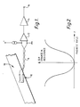
- a card reader in accordance with the invention has an input stage comprising a magnetoresistive sensor 10, coupled by a twisted pair 11 of conductors to preamplifier 12.
- the output of the amplifier 12 is coupled to a comparator 14 having an output 16.
- a comparator 14 having an output 16.
- an electrical signal representative of coded data in the magnetic layer 18 is produced on conductors 11.
- the sensor 10 is unbiased.
- the magnetoresistive sensor 10 has a symmetrical output vs. magnetic field characteristic. This holds true if the sensor is unbiased. If the magnetisation of the magnetic layer is bidirectional, a doubling of the pulse repetition rate of the electrical signal with respect to the repetition rate of the magnetic field variations will result as the magnetic layer 18 passes the sensor 10. The doubling effect is shown in Figures 3A to 3C.
- the waveform of Figure 3A is an example of two frequency phase coherent (F2F) recording, which is a method of recording data on a recording medium allowing the derivation of a clock waveform from the recorded data.
- the medium may be a magnetic layer on a swipe card or the like which, it will be appreciated, may be passed through a card reader at any speed over a wide range of speeds, and with some acceleration or deceleration.
- the waveform may appear as in Figure 3B, while passage through the comparator 14 results in the waveform of Figure 3C. It will be seen from Figure 3C that the pulse width associated with a zero is greater than the width of the pulse (two) associated with a '1'.
- the ratio of the pulse widths associated with '1's and '0's is a function of previously defined parameters.
- the digital pulsesignal from the comparator is fed to one input of an AND gate 20 having its other input coupled to a clock generator 22 arranged to feed to the AND gate 20 a fast clock waveform of a frequency considerably greater than the pulse repetition rate of the incoming data pulses.
- the resulting gated clock waveform is fed to a counter 24 having an output coupled to a microprocessor 26.
- the width of each positive-going pulse of the waveform of Figure 4 is measured by counting the corresponding gated clock pulses in the counter 24. The resulting count is stored by the microprocessor 26 in an associated memory 28.
- Evaluation of the pulses is performed by comparing in the microprocessor 26 the stored counts of different pulses. It will be understood that the decoding process may include storing the whole output obtained by passing a swipe card across the sensor before the comparison of pulse widths begins. Alternatively, storage and comparison may be performed on a real time basis.
- the micro-processor 28 stores in the memory and compares the count P n-a for the last pulse representing a '0; and the count P n for a pulse to be decoded. If P n is less than P n-a by a preset percentage, the pulse corresponding to P n is decoded as a '1' providing the next incoming pulse P n+1 also has the characteristic of a '1'. When this occurs, the two pulses are decoded as a single data bit '1'. This provides a form of error checking. If P n is equal to P n-a within a fixed tolerance band, then the pulse is decoded as a '0'.
- the counts representing '1's can be used as reference counts, the microprocessor comparing the count P n of the pulse to be decoded with the count of the last occurring '1'. This method is satisfactory provided that the incoming data does not include large numbers of '1's or '0's in succession, as appropriate, when an acceleration or deceleration of the magnetic strip could result in errors.
- a second method involves instead the comparison of P n with P n-1 is the width of the preceding pulse plus a fixed percentage in the case of a '0', or the total width of the two preceding pulses associated with a '1' plus a fixed percentage of the sum of the pulses.
- the comparisons are performed with certain tolerances added to or subtracted from the reference count depending, for example, on the expected noise level or recording density (the higher the density the smaller the variation from bit to bit), the expected range of speed of the card in the reader, the accuracy of measurement of pulse width (i.e. the fast clock frequency), and the hysteresis of the comparator 14.
- the fast clock frequency is 100kHz.
- the micro- processor 26 may be programmed to generate an output signal dependent on the values of counts received from the counter 24 to vary the clock frequency.
- the output signal from the micro-processor may be used to reduce the clock frequency.
- continuous feedback may be used, whereby the clock frequency is maintained substantially equal to a fixed multiple of the underlying pulse repetition rate of the incoming data, so as to maintain constant resolution in the pulse width measurement.
- the frequency of the clock could be introduced into the decoding algorithm in the microprocessor as a multiplying factor. This allows accurate measurement of pulse width over a wide range of pulse repetition rates.
- decoding is achieved in real time.
- More complex statistical methods may then be applied to decode the data thus improving the reliability of the reading system. For example, in an insertion card reader in which the data may be read when the card is inserted and when it is withdrawn, post-processing of the pulse widths measured during insertion and when the card is removed may be used statistically to improve the reading reliability.
- magnetoresistive sensor 10 it is advantageous to operate in a biased mode, i.e. exclusively on one side or other of the characteristic shown in Figure 2. In this case, however, no frequency doubling occurs, and it is necessary to count both 'high' and 'low' excursions of the resulting signal.
- random logic and an arithmetic logic unit may be used to perform the same functions as the microprocessor.
- Figure 5B shows the analogue output from a recording medium in which the amplified pulse heights associated for a '1' are significantly different from those of a '0'. The actual differences depend on the characteristics of the head and recording.
- Figure 5C shows the comparator output if the switching threshold is above the peak of the analogue signal from the pulses associated with a '1'.
- P n-2 and P n-1 are pulses associated with '0; as in the previous case, R n and R n+1 occur for example due to a single '1' and two consecutive '1's respectively.
- the number of '1's associated with these pulses can be deduced from P n-1 .
- the ratios between R n and R n-1 are a function of the previously discussed characteristics of the recording system. Similar techniques can be applied to the pulses arising from other bit patterns. In this instance both high and low periods of the comparator output must be timed using two sets of counts.
Landscapes
- Engineering & Computer Science (AREA)
- Signal Processing (AREA)
- Signal Processing For Digital Recording And Reproducing (AREA)
- Recording Or Reproducing By Magnetic Means (AREA)
Applications Claiming Priority (2)
| Application Number | Priority Date | Filing Date | Title |
|---|---|---|---|
| GB888803504A GB8803504D0 (en) | 1988-02-16 | 1988-02-16 | Method of decoding recorded data |
| GB8803504 | 1988-02-16 |
Publications (3)
| Publication Number | Publication Date |
|---|---|
| EP0329412A2 true EP0329412A2 (de) | 1989-08-23 |
| EP0329412A3 EP0329412A3 (en) | 1990-05-16 |
| EP0329412B1 EP0329412B1 (de) | 1994-06-08 |
Family
ID=10631766
Family Applications (1)
| Application Number | Title | Priority Date | Filing Date |
|---|---|---|---|
| EP89301439A Expired - Lifetime EP0329412B1 (de) | 1988-02-16 | 1989-02-15 | Wiedergabe und Dekodierung aufgezeichneter Daten mit variabler Geschwindigkeit unter Verwendung eines magneto-resistiven Sensors |
Country Status (4)
| Country | Link |
|---|---|
| EP (1) | EP0329412B1 (de) |
| AT (1) | ATE107071T1 (de) |
| DE (1) | DE68915807D1 (de) |
| GB (2) | GB8803504D0 (de) |
Families Citing this family (1)
| Publication number | Priority date | Publication date | Assignee | Title |
|---|---|---|---|---|
| CN114509709B (zh) * | 2021-11-26 | 2025-09-30 | 成都芯进电子股份有限公司 | 一种二维amr传感器开关芯片信号检测架构及检测方法 |
Family Cites Families (7)
| Publication number | Priority date | Publication date | Assignee | Title |
|---|---|---|---|---|
| US3838251A (en) * | 1971-06-29 | 1974-09-24 | Monarch Marking Systems Inc | Method of interpreting a coded record |
| CA955685A (en) * | 1971-07-01 | 1974-10-01 | Roland O. Barnes | Rate adaptive nonsynchronous demodulator apparatus for two level binary signals |
| DE2208309C3 (de) * | 1972-02-22 | 1975-09-18 | Nixdorf Computer Ag, 4790 Paderborn | Verfahren zur Auswertung von Informationen in Form gruppenweise zusammengefaßter Informationselemente aus einfarbig gedruckten Strichen, Anordnung zur Darstellung von Informationen zur Auswertung nach dem Verfahren und Schaltungsanordnung zur Durchführung des Verfahrens |
| US3859631A (en) * | 1973-07-16 | 1975-01-07 | Comsci Data Inc | Method and apparatus for decoding binary digital signals |
| JPS5085320A (de) * | 1973-11-27 | 1975-07-09 | ||
| GB1528381A (en) * | 1974-11-08 | 1978-10-11 | Ibm | Processing bar coded data |
| FR2428875A1 (fr) * | 1978-06-16 | 1980-01-11 | Cii Honeywell Bull | Procede et appareil de lecture d'informations codees magnetiquement |
-
1988
- 1988-02-16 GB GB888803504A patent/GB8803504D0/en active Pending
-
1989
- 1989-02-15 GB GB8903418A patent/GB2216316B/en not_active Expired - Lifetime
- 1989-02-15 EP EP89301439A patent/EP0329412B1/de not_active Expired - Lifetime
- 1989-02-15 DE DE68915807T patent/DE68915807D1/de not_active Expired - Lifetime
- 1989-02-15 AT AT89301439T patent/ATE107071T1/de not_active IP Right Cessation
Also Published As
| Publication number | Publication date |
|---|---|
| EP0329412B1 (de) | 1994-06-08 |
| GB2216316A (en) | 1989-10-04 |
| EP0329412A3 (en) | 1990-05-16 |
| GB8903418D0 (en) | 1989-04-05 |
| GB8803504D0 (en) | 1988-03-16 |
| ATE107071T1 (de) | 1994-06-15 |
| DE68915807D1 (de) | 1994-07-14 |
| GB2216316B (en) | 1992-05-13 |
Similar Documents
| Publication | Publication Date | Title |
|---|---|---|
| DE69222412T2 (de) | Verfahren und Gerät zur Dekodierung von von einem magnetischen Datenträger gelesene F2F-Signalen | |
| EP1185950B1 (de) | Magnetstreifen-lesegerät | |
| US5616904A (en) | Data verification method and magnetic media therefor | |
| US4254441A (en) | Digital code reader | |
| US5254843A (en) | Securing magnetically encoded data using timing variations in encoded data | |
| US5204513A (en) | Decoder for magnetic stripe recording | |
| US5229894A (en) | Method and apparatus for reading and decoding information using a magnetoresistive sensor | |
| US6431445B1 (en) | Magnetic stripe card verification system | |
| US5358088A (en) | Horizontal magnetoresistive head apparatus and method for detecting magnetic data | |
| KR960002148B1 (ko) | 마그네트기록카드의 이진정보 해독방법 | |
| JP3395210B2 (ja) | 同期信号検出器及び同期信号検出方法 | |
| DE69800831T2 (de) | Verfahren und gerät zur aufzeichnung einer taktspur auf einem aufzeichnungsmedium | |
| US4012786A (en) | Magnetic data decoder | |
| US4176259A (en) | Read apparatus | |
| EP0329412A2 (de) | Wiedergabe und Dekodierung aufgezeichneter Daten mit variabler Geschwindigkeit unter Verwendung eines magneto-resistiven Sensors | |
| CA1059238A (en) | Code converter | |
| KR870010459A (ko) | 빠르게 변하는 주사속도하에 바코드를 판독하는 방법 및 장치 | |
| CN112395895A (zh) | 磁条软件解码方法、装置及计算机可读存储介质 | |
| US6445519B1 (en) | Basline instability detector | |
| EP1033670A2 (de) | Digitaler magnetischer Lesekanal und Verfahren | |
| US4449154A (en) | Sampling time control circuit for use in an audio cassette tape data processor | |
| JP3516038B2 (ja) | 磁気媒体読取り装置 | |
| CN114299676B (zh) | 一种提高pos终端磁卡正确识别刷卡的方法 | |
| JPS62119770A (ja) | 磁気記録再生装置 | |
| JPH06203194A (ja) | 走行式カードリーダ装置 |
Legal Events
| Date | Code | Title | Description |
|---|---|---|---|
| PUAI | Public reference made under article 153(3) epc to a published international application that has entered the european phase |
Free format text: ORIGINAL CODE: 0009012 |
|
| AK | Designated contracting states |
Kind code of ref document: A2 Designated state(s): AT BE CH DE ES FR GR IT LI LU NL SE |
|
| PUAL | Search report despatched |
Free format text: ORIGINAL CODE: 0009013 |
|
| AK | Designated contracting states |
Kind code of ref document: A3 Designated state(s): AT BE CH DE ES FR GR IT LI LU NL SE |
|
| 17P | Request for examination filed |
Effective date: 19901116 |
|
| 17Q | First examination report despatched |
Effective date: 19921201 |
|
| GRAA | (expected) grant |
Free format text: ORIGINAL CODE: 0009210 |
|
| AK | Designated contracting states |
Kind code of ref document: B1 Designated state(s): AT BE CH DE ES FR GR IT LI LU NL SE |
|
| PG25 | Lapsed in a contracting state [announced via postgrant information from national office to epo] |
Ref country code: IT Free format text: LAPSE BECAUSE OF FAILURE TO SUBMIT A TRANSLATION OF THE DESCRIPTION OR TO PAY THE FEE WITHIN THE PRE;WARNING: LAPSES OF ITALIAN PATENTS WITH EFFECTIVE DATE BEFORE 2007 MAY HAVE OCCURRED AT ANY TIME BEFORE 2007. THE CORRECT EFFECTIVE DATE MAY BE DIFFERENT FROM THE ONE RECORDED.SCRIBED TIME-LIMIT Effective date: 19940608 Ref country code: FR Effective date: 19940608 Ref country code: ES Free format text: THE PATENT HAS BEEN ANNULLED BY A DECISION OF A NATIONAL AUTHORITY Effective date: 19940608 Ref country code: AT Effective date: 19940608 Ref country code: BE Effective date: 19940608 Ref country code: GR Free format text: LAPSE BECAUSE OF FAILURE TO SUBMIT A TRANSLATION OF THE DESCRIPTION OR TO PAY THE FEE WITHIN THE PRESCRIBED TIME-LIMIT Effective date: 19940608 Ref country code: NL Effective date: 19940608 |
|
| REF | Corresponds to: |
Ref document number: 107071 Country of ref document: AT Date of ref document: 19940615 Kind code of ref document: T |
|
| REF | Corresponds to: |
Ref document number: 68915807 Country of ref document: DE Date of ref document: 19940714 |
|
| PG25 | Lapsed in a contracting state [announced via postgrant information from national office to epo] |
Ref country code: SE Effective date: 19940908 |
|
| PG25 | Lapsed in a contracting state [announced via postgrant information from national office to epo] |
Ref country code: DE Effective date: 19940909 |
|
| EN | Fr: translation not filed | ||
| NLV1 | Nl: lapsed or annulled due to failure to fulfill the requirements of art. 29p and 29m of the patents act | ||
| PG25 | Lapsed in a contracting state [announced via postgrant information from national office to epo] |
Ref country code: LI Effective date: 19950228 Ref country code: CH Effective date: 19950228 Ref country code: LU Free format text: LAPSE BECAUSE OF NON-PAYMENT OF DUE FEES Effective date: 19950228 |
|
| PLBE | No opposition filed within time limit |
Free format text: ORIGINAL CODE: 0009261 |
|
| STAA | Information on the status of an ep patent application or granted ep patent |
Free format text: STATUS: NO OPPOSITION FILED WITHIN TIME LIMIT |
|
| 26N | No opposition filed |