EP0329472A2 - Schwimmbeckenreinigungsvorrichtung - Google Patents
Schwimmbeckenreinigungsvorrichtung Download PDFInfo
- Publication number
- EP0329472A2 EP0329472A2 EP89301577A EP89301577A EP0329472A2 EP 0329472 A2 EP0329472 A2 EP 0329472A2 EP 89301577 A EP89301577 A EP 89301577A EP 89301577 A EP89301577 A EP 89301577A EP 0329472 A2 EP0329472 A2 EP 0329472A2
- Authority
- EP
- European Patent Office
- Prior art keywords
- members
- wing
- draw element
- edges
- displacing
- Prior art date
- Legal status (The legal status is an assumption and is not a legal conclusion. Google has not performed a legal analysis and makes no representation as to the accuracy of the status listed.)
- Granted
Links
Images

Classifications
-
- E—FIXED CONSTRUCTIONS
- E04—BUILDING
- E04H—BUILDINGS OR LIKE STRUCTURES FOR PARTICULAR PURPOSES; SWIMMING OR SPLASH BATHS OR POOLS; MASTS; FENCING; TENTS OR CANOPIES, IN GENERAL
- E04H4/00—Swimming or splash baths or pools
- E04H4/14—Parts, details or accessories not otherwise provided for
- E04H4/16—Parts, details or accessories not otherwise provided for specially adapted for cleaning
-
- E—FIXED CONSTRUCTIONS
- E04—BUILDING
- E04H—BUILDINGS OR LIKE STRUCTURES FOR PARTICULAR PURPOSES; SWIMMING OR SPLASH BATHS OR POOLS; MASTS; FENCING; TENTS OR CANOPIES, IN GENERAL
- E04H4/00—Swimming or splash baths or pools
- E04H4/14—Parts, details or accessories not otherwise provided for
- E04H4/16—Parts, details or accessories not otherwise provided for specially adapted for cleaning
- E04H4/1681—Cleaning whips
-
- Y—GENERAL TAGGING OF NEW TECHNOLOGICAL DEVELOPMENTS; GENERAL TAGGING OF CROSS-SECTIONAL TECHNOLOGIES SPANNING OVER SEVERAL SECTIONS OF THE IPC; TECHNICAL SUBJECTS COVERED BY FORMER USPC CROSS-REFERENCE ART COLLECTIONS [XRACs] AND DIGESTS
- Y10—TECHNICAL SUBJECTS COVERED BY FORMER USPC
- Y10T—TECHNICAL SUBJECTS COVERED BY FORMER US CLASSIFICATION
- Y10T403/00—Joints and connections
- Y10T403/32—Articulated members
- Y10T403/32114—Articulated members including static joint
- Y10T403/32196—Articulate joint is ball and socket
Definitions
- THIS INVENTION relates to a device for cleaning a swimming pool.
- a device for cleaning a swimming pool which includes a pair of spaced wing-like members which have leading and trailing edges and which define a mouth-like opening at leading edges thereof; a foraminous bag secured to the wing-like members; and a draw element which is hingedly attached to the wing-like members for the wing-like members to be pivotal relative to the draw element, about a hinge axis, with the device having a specific gravity greater than unity and a centre of gravity and a centre of drag which are located so that a net couple is exerted on the wing-like members when the device falls freely in the water which tends to position the trailing edge of each member above the leading edge of that member.
- centre of drag is the point through which a resultant force passes equivalent to the drag force that the device experiences as it drops freely in water under the action of gravity, with the wing-like members extending and oriented generally horizontally.
- the wing-like members may be parallel. They may further be the same length and may be aligned so that the opening is substantially regtangular. Bridging webs may extend between the ends of the wing-like members, to support the wing-like members in their spaced configuration and to define the mouth-like opening. Further bridging webs may be provided intermediate the ends of the wing-like members.
- the draw element may be secured to the bridging webs at leading ends thereof.
- the draw element is centrally secured to the bridging webs so that the structure defined by the wing-like members and the bridging webs is symmetrical about a median plane located midway between and parallel to the wing-like members.
- the hinge axis is close to the leading edges of the wing-like members.
- the centre of gravity may be caused to be closer to the hinge axis by appropriate shaping of the wing-like and other members.
- mass members may be provided which are secured either to the wing-like members and/or the bridge members and/or the draw element, to ensure that the centre of gravity is in the desired position.
- Hinging may be provided by specific hinge members, or by means of hinge regions which have a reduced thickness.
- Fins may be provided which are carried by the wing-like members on their opposed outer surfaces. Fins may also be carried by the outer bridging webs on their outer sides.
- the draw element may be forked having prongs extending from a leading bar.
- the draw element may be attached to a displacing component.
- the displacing component may be hollow, may be connectable to a hose through which water under pressure is supplied and may have one or more jet nozzles which are directed towards the draw element such that water issuing therefrom causes the component and the draw element to be displaced.
- the draw element is pivotally attached to the displacing component, by means of a ball-and-socket joint.
- the wing-like members may be such that, when the device is drawn through the water, with the wing-like members tilted as a result of the net couple exerted by the drag force referred to above, they experience a downwardly directed hydro-dynamic force that tends to assist the weight of the device to cause the device to move downwardly in the water.
- the Applicant believes that, preferably, the centre of lift should be closer to the hinge axis than the centre of drag.
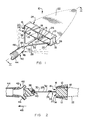
- the device is designated generally by reference numeral 10.
- the device 10 has two wings 12 which are parallel and spaced apart such that leading edges 14 thereof partly define an opening 16.
- the wings 12 have an aerofoil profile.
- the wings 12 are held apart by bridge members 18. There are three bridge members 18, one at either end of the wings 12 and the third midway between the ends of the wings 12.
- the opening 16 is further defined by leading edges 20 of the end bridge members 18.
- a foraminous bag 22 is secured to the trailing edges 24 of the wings 12 and end bridge members 18. It will be appreversted that, in use, as described below, debris in the water passes through the opening 16 as the device 10 moves through the water, to be collected in the bag 22.
- a number of fins 26 are secured to the outer surfaces of the wings 12 and the end bridge members 18. These fins 26 are substantially triangular with their trailing ends being wider.
- the device 10 further has a draw element 28.
- the draw element 28 is forked having a leading bar 30 and three prongs 32.
- the prongs 32 are centrally attached to the leading edges of the bridge members 18 so that the device 10 is substantially symmetrical about a median plane that passes through the middle of the bridge members 18.
- the prongs 32 Close to their free ends, the prongs 32 have hinge regions 34 which are of a reduced thickness to provide a hinge function. These hinge regions 34 are aligned to define a hinge axis that extends parallel to the leading edges 14 of the wings 12 and midway between them.
- Lead weights 36 are secured to the prongs 32 close to their hinge regions 34. The purpose of these weights 36 will be explained below.
- the bar 30 has, at its leading end a ball 38 which is received in a socket 40 in the trailing end of a displacing component 42.
- the ball 38 and socket 40 define a ball-and-socket joint so that the bar 30 may pivot in two degrees of freedom relative to the component 42 and also swivel.
- the component 42 is hollow and is engageable at its leading end with a flexible hose 44 through which, in use, water is supplied under pressure.
- the component 42 further has two jet nozzles 46 which are directed in a downstream direction so that in use a draw force in the direction of arrow 48 is exerted on the component 42 and which is transfered to the draw element 28.
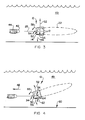
- Figure 3 shows schematically the forces experienced by the device 10 when it is at rest, ie. not being drawn through water 49 in the pool.
- the device 10 has a specific gravity that is greater than unity so that it sinks in the water 49.
- the device 10 has centre of gravity 50 which passes through the wings 12 close to the leading edges 14 thereof. If the wngs 12 extend horizontally from front-to-back and side-to-side, as shown schematically in Figure 3, and the device 10 is allowed to fall through the water 49 under the action of gravity, the various parts of the device 10 will experience drag forces which have a resultant 52 that passes through a centre of drag 54.
- the centre of drag 54 also passes through the wings 12, with the centre of gravity between it and the hinge axis 34.
- the device 10 is designed such that the weights 56, the distance of the centre of gravity 50 from the hinge region 34, the drag force 52 and the distance of the centre of drag 54 from the hinge region 34 exerts a net couple on the wings 12 about the hinge axis 34 that is anti-clockwise when seen in Figure 3, as shown by the arrow 58.
- the wings 12 would tilt so that their leading edges 14 are below their trailing edges 24.
- the weights 38 ensure that the centre of gravity 50 is in the desired position.
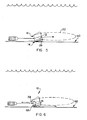
- the operation of the device 10 as it moves through the water 49 in the direction of arrow 48 is shown.
- the device 10 will experience a drag force 52 substantially as it does when at rest and a gravitational force 56 which tilt the wings 12 as described above.
- the wings 12 have a suitable profile so that a hydro-dynamic force 62 is exerted on the wings 12 which is downwardly directed when the wings 12 are tilted as described, ie. with their trailing edges above their leading edges.
- This negative-lift force 62 acts through a centre of lift 64 and assists the weights 56 in displacing the device 10 downwardly towards the floor 60.
- the hydro-dynamic negative-lift force 62 will depend on the angle of attack of the wings 12 and the speed with which the device moves through the water. Such devices are usually operated at speeds of between about 0,5 feet/sec and 5 feet/sec, i.e. between about 0,15 m/sec and 1.5 m/sec. This force will cause the angle of attack of the wings 12 to decrease in comparison with the angle when falling freely, and the faster the device moves, the closer the wings will pivot towards a zero angle of attack. However, as the angle of attack decreases the magnitude of the force 62 decreases, and the Applicant accordingly believes that the device will move down in the water, towards the floor 60 of the pool, with the leading edges 14 of the wings 12 below their trailing edges.
- the wings 12 will pivot about the hinge axis 34 to assist the device 10 in passing over the protrusion 68. The forces on the device 10 will thereafter ensure that the device 10 returns to the floor 60 with the desired orientation.
- FIG. 7 a further embodiment of a device in accordance with the invention is shown.
- This embodiment is similar to that shown in Figures 1 and 2 and is similarly referenced.
- the wings 12 are flat as is clearly seen in Figure 8
- the bag 22 is fast with a frame 72 that has lugs 74 which clip onto pins 76
- the component 42 has a pin 82 with a head 84 that is held in a socket arrangement formed by two parts 78 and 80 at the free end of the bar 30.
- the parts 78 and 80 clip together.
Landscapes
- Engineering & Computer Science (AREA)
- Architecture (AREA)
- Civil Engineering (AREA)
- Structural Engineering (AREA)
- Cleaning By Liquid Or Steam (AREA)
- Farming Of Fish And Shellfish (AREA)
- Massaging Devices (AREA)
- Vehicle Cleaning, Maintenance, Repair, Refitting, And Outriggers (AREA)
- Cleaning In General (AREA)
- Devices For Medical Bathing And Washing (AREA)
Priority Applications (1)
| Application Number | Priority Date | Filing Date | Title |
|---|---|---|---|
| AT89301577T ATE69289T1 (de) | 1988-02-18 | 1989-02-17 | Schwimmbeckenreinigungsvorrichtung. |
Applications Claiming Priority (2)
| Application Number | Priority Date | Filing Date | Title |
|---|---|---|---|
| ZA881142 | 1988-02-18 | ||
| ZA881142 | 1988-02-18 |
Publications (3)
| Publication Number | Publication Date |
|---|---|
| EP0329472A2 true EP0329472A2 (de) | 1989-08-23 |
| EP0329472A3 EP0329472A3 (en) | 1989-10-11 |
| EP0329472B1 EP0329472B1 (de) | 1991-11-06 |
Family
ID=25579173
Family Applications (1)
| Application Number | Title | Priority Date | Filing Date |
|---|---|---|---|
| EP89301577A Expired - Lifetime EP0329472B1 (de) | 1988-02-18 | 1989-02-17 | Schwimmbeckenreinigungsvorrichtung |
Country Status (6)
| Country | Link |
|---|---|
| US (1) | US4994178A (de) |
| EP (1) | EP0329472B1 (de) |
| AT (1) | ATE69289T1 (de) |
| AU (1) | AU614334B2 (de) |
| CA (1) | CA1307881C (de) |
| DE (1) | DE68900397D1 (de) |
Cited By (2)
| Publication number | Priority date | Publication date | Assignee | Title |
|---|---|---|---|---|
| FR2785000A1 (fr) * | 1998-10-21 | 2000-04-28 | Pascal Louis Albert Abadie | Systeme de ramassage automatique des dechets reposant sur les fonds marins |
| WO2011128860A3 (en) * | 2010-04-13 | 2012-03-22 | Johan Frederik Schutte | Cleaning of swimming pools |
Families Citing this family (35)
| Publication number | Priority date | Publication date | Assignee | Title |
|---|---|---|---|---|
| US5043060A (en) * | 1990-10-09 | 1991-08-27 | Joseph Brennan | Swimming pool skimmer |
| US5108593A (en) * | 1991-02-11 | 1992-04-28 | Passaic Valley Sewerage Commissioners | Apparatus for collecting substances floating in an effluent stream |
| US5068929A (en) * | 1991-02-25 | 1991-12-03 | Weiner Robert I | Edge retainer for a floating pool cover |
| US5264122A (en) * | 1992-03-11 | 1993-11-23 | 21St Century Pool Technology | Stationary surface pool cleaner |
| US5454940A (en) * | 1992-03-11 | 1995-10-03 | George A. Lakotish | Stationary swimming pool skimmer with water jet directing means |
| US5350508A (en) * | 1992-03-24 | 1994-09-27 | Watt Lourens V D | Pool skimming device |
| US5536397A (en) * | 1994-04-25 | 1996-07-16 | D'offay; Robert A. | Pool skimming device |
| US5422001A (en) * | 1994-05-04 | 1995-06-06 | Yagoda; Gordon B. | Enlarged pool skimmer with a buoyancy component |
| US6302277B1 (en) | 1994-08-25 | 2001-10-16 | Eric Resh | Swimming pool cleaning tool |
| US5473786A (en) | 1994-08-25 | 1995-12-12 | Resh; Eric | Swimming pool cleaning tool, and related method |
| EP0835357B1 (de) * | 1995-06-27 | 2003-09-17 | Melvyn L. Henkin | Automatisches schwimmbadreinigungssystem |
| US5614085A (en) * | 1995-07-11 | 1997-03-25 | Platt, Iii; James B. | Omnidirectional skimmer |
| EP1695770A1 (de) * | 1996-06-26 | 2006-08-30 | Melvyn L. Henkin | Automatisches Schwimmbeckenreinigungssystem mit positivem Druck |
| US6039886A (en) * | 1997-06-25 | 2000-03-21 | Henkin; Melvyn L. | Water suction powered automatic swimming pool cleaning system |
| US6090219A (en) * | 1997-05-06 | 2000-07-18 | Henkin; Melvyn L. | Positive pressure automatic swimming poor cleaning system |
| US5919359A (en) * | 1997-11-11 | 1999-07-06 | Bisseker; Robin | Portable pool skimmer |
| US6086759A (en) * | 1997-11-11 | 2000-07-11 | Bisseker; Robin | Portable pool skimmer |
| ZA9811831B (en) * | 1997-12-26 | 1999-06-23 | Henkin Melvyn Lane | Positive pressure automatic swimming pool cleaning system |
| CA2342489C (en) * | 2000-04-07 | 2004-03-23 | Marc Riverin | Device for sea urchins picking |
| WO2005001221A2 (en) * | 2003-06-02 | 2005-01-06 | Henkin-Laby, Llc. | Positive pressure pool cleaner propulsion subsystem |
| GB2459242A (en) * | 2007-12-14 | 2009-10-21 | Berkeley Charles Lewis | Weed rake with aqua foil to clear underwater plants |
| US8343339B2 (en) | 2008-09-16 | 2013-01-01 | Hayward Industries, Inc. | Apparatus for facilitating maintenance of a pool cleaning device |
| US8006474B2 (en) * | 2009-04-20 | 2011-08-30 | Radius Garden Llc | Pond cleaning implement |
| US8784652B2 (en) | 2010-09-24 | 2014-07-22 | Poolvergnuegen | Swimming pool cleaner with a rigid debris canister |
| US8869337B2 (en) | 2010-11-02 | 2014-10-28 | Hayward Industries, Inc. | Pool cleaning device with adjustable buoyant element |
| US9976316B2 (en) | 2011-07-28 | 2018-05-22 | Resh, Inc. | Pool cleaning apparatus and related methods |
| US11105108B2 (en) | 2011-07-28 | 2021-08-31 | Resh, Inc. | Pool cleaning apparatus and related methods |
| WO2013063645A1 (en) * | 2011-11-01 | 2013-05-10 | Pool Systems Pty Ltd | A device for collecting submerged debris from a body of water |
| US9677294B2 (en) | 2013-03-15 | 2017-06-13 | Hayward Industries, Inc. | Pool cleaning device with wheel drive assemblies |
| CA2905845A1 (en) * | 2013-03-15 | 2014-09-25 | Hayward Industries, Inc. | Swimming pool pressure cleaner including automatic timing mechanism |
| US9745767B2 (en) | 2013-03-15 | 2017-08-29 | Hayward Industries, Inc. | Swimming pool pressure cleaner including automatic timing mechanism |
| US9938742B2 (en) * | 2015-03-31 | 2018-04-10 | Benjamin Fertic | Pool cleaning device |
| AU2019382306B2 (en) * | 2018-11-22 | 2024-04-18 | Aero-Tech Pty Ltd | Downforce sweeper |
| US11554333B2 (en) * | 2020-06-24 | 2023-01-17 | Jason Farley | Method of filtering water being returned to a swimming pool |
| FR3165915A1 (fr) * | 2024-08-30 | 2026-03-06 | Nodinnov | Épuisette de fond pour équipement aquatique, notamment pour piscine |
Family Cites Families (13)
| Publication number | Priority date | Publication date | Assignee | Title |
|---|---|---|---|---|
| US2658625A (en) * | 1948-08-02 | 1953-11-10 | Arthur W Rafferty | Header strainer for liquid lines |
| US2902705A (en) * | 1956-10-08 | 1959-09-08 | Eistrup Joseph | Pool cleaner |
| US3063077A (en) * | 1959-04-20 | 1962-11-13 | Andrew L Pansini | Device for the cleaning of swimming pools and the like |
| US3921654A (en) * | 1971-06-07 | 1975-11-25 | Andrew L Pansini | Automatic swimming pool cleaner |
| US3825356A (en) * | 1972-07-14 | 1974-07-23 | American Hoist & Derrick Co | Two-piece swage fittings |
| DE2360029A1 (de) * | 1973-12-01 | 1975-06-05 | Andrew L Pansini | Automatisches reinigungsgeraet fuer schwimmbecken |
| US3863237A (en) * | 1973-12-10 | 1975-01-28 | Norman N Doerr | Lake raking apparatus |
| US4003100A (en) * | 1975-01-15 | 1977-01-18 | Whitaker James L | Pool cleaning device |
| US4040864A (en) * | 1976-03-12 | 1977-08-09 | Steeves Claire L | Device and method for cleaning leaves and debris from swimming pools |
| US4338697A (en) * | 1980-08-14 | 1982-07-13 | Caleb Broadwater | Simplified pool cleaning apparatus |
| US4518495A (en) * | 1982-09-17 | 1985-05-21 | Harding Henry W | Pool skimmer |
| US4778599A (en) * | 1984-03-12 | 1988-10-18 | Spooner Est | Cleaning of a body of liquid by surface agitation |
| US4749478A (en) * | 1986-11-07 | 1988-06-07 | Spooner Est | Cleaning unit for collecting debris in a swimming pool |
-
1989
- 1989-02-17 AT AT89301577T patent/ATE69289T1/de active
- 1989-02-17 DE DE8989301577T patent/DE68900397D1/de not_active Expired - Lifetime
- 1989-02-17 EP EP89301577A patent/EP0329472B1/de not_active Expired - Lifetime
- 1989-02-20 AU AU30118/89A patent/AU614334B2/en not_active Expired
- 1989-02-21 CA CA000591600A patent/CA1307881C/en not_active Expired - Lifetime
- 1989-02-22 US US07/314,410 patent/US4994178A/en not_active Expired - Lifetime
Cited By (3)
| Publication number | Priority date | Publication date | Assignee | Title |
|---|---|---|---|---|
| FR2785000A1 (fr) * | 1998-10-21 | 2000-04-28 | Pascal Louis Albert Abadie | Systeme de ramassage automatique des dechets reposant sur les fonds marins |
| WO2011128860A3 (en) * | 2010-04-13 | 2012-03-22 | Johan Frederik Schutte | Cleaning of swimming pools |
| AU2011241883B2 (en) * | 2010-04-13 | 2015-12-24 | Poolsnake Cc | Cleaning of swimming pools |
Also Published As
| Publication number | Publication date |
|---|---|
| ATE69289T1 (de) | 1991-11-15 |
| AU3011889A (en) | 1989-08-24 |
| DE68900397D1 (de) | 1991-12-12 |
| EP0329472B1 (de) | 1991-11-06 |
| US4994178A (en) | 1991-02-19 |
| AU614334B2 (en) | 1991-08-29 |
| CA1307881C (en) | 1992-09-29 |
| EP0329472A3 (en) | 1989-10-11 |
Similar Documents
| Publication | Publication Date | Title |
|---|---|---|
| EP0329472A2 (de) | Schwimmbeckenreinigungsvorrichtung | |
| US4281995A (en) | Automatic pool cleaners | |
| US4749478A (en) | Cleaning unit for collecting debris in a swimming pool | |
| US5179761A (en) | Aerodynamic windshield wiper superstructure | |
| US4839063A (en) | Cleaning of a body of liquid | |
| US12416173B1 (en) | Swimming pool cleaner with orientable liquid flux | |
| US4778599A (en) | Cleaning of a body of liquid by surface agitation | |
| US6601255B1 (en) | Pool cleaner | |
| US9249590B2 (en) | Fluid flow deflector assemblies principally for connection to sweep tail hoses of automatic swimming pool cleaners | |
| EP1163847B1 (de) | Landwirtschaftliche Feldspritze | |
| WO1997015737A1 (en) | Anti-clogging, variable throat suction nozzle and suctioncleaning device equipped therewith | |
| EP0783866A3 (de) | Wischgerät | |
| JP2000508915A (ja) | 拡網板 | |
| US6250565B1 (en) | Flamingo sprinkler | |
| US5391296A (en) | Pool skimmer deflecting device | |
| US10889972B2 (en) | Bracket for hand shower | |
| US5974703A (en) | Drag-along snow plow apparatus | |
| US6645375B2 (en) | Flexible power conduit for automatic pool cleaners | |
| US12359751B2 (en) | Hose support assembly | |
| CN107600978A (zh) | 可定向的零件输送装置和激光打标设备 | |
| CN218458052U (zh) | 基站及自移动系统 | |
| NL8601716A (nl) | Afmeerinrichting. | |
| KR100437424B1 (ko) | 글라이더의 꼬리 날개 가변 장치 | |
| CN2452446Y (zh) | 自卸式撮机 | |
| CN112942095A (zh) | 一种人行桥梁栏杆的自清洁装置 |
Legal Events
| Date | Code | Title | Description |
|---|---|---|---|
| PUAI | Public reference made under article 153(3) epc to a published international application that has entered the european phase |
Free format text: ORIGINAL CODE: 0009012 |
|
| AK | Designated contracting states |
Kind code of ref document: A2 Designated state(s): AT BE CH DE ES FR GB GR IT LI LU NL SE |
|
| PUAL | Search report despatched |
Free format text: ORIGINAL CODE: 0009013 |
|
| AK | Designated contracting states |
Kind code of ref document: A3 Designated state(s): AT BE CH DE ES FR GB GR IT LI LU NL SE |
|
| 17P | Request for examination filed |
Effective date: 19900411 |
|
| 17Q | First examination report despatched |
Effective date: 19900911 |
|
| GRAA | (expected) grant |
Free format text: ORIGINAL CODE: 0009210 |
|
| AK | Designated contracting states |
Kind code of ref document: B1 Designated state(s): AT BE CH DE ES FR GB GR IT LI LU NL SE |
|
| PG25 | Lapsed in a contracting state [announced via postgrant information from national office to epo] |
Ref country code: GR Free format text: LAPSE BECAUSE OF FAILURE TO SUBMIT A TRANSLATION OF THE DESCRIPTION OR TO PAY THE FEE WITHIN THE PRESCRIBED TIME-LIMIT Effective date: 19911106 Ref country code: IT Free format text: LAPSE BECAUSE OF FAILURE TO SUBMIT A TRANSLATION OF THE DESCRIPTION OR TO PAY THE FEE WITHIN THE PRE;WARNING: LAPSES OF ITALIAN PATENTS WITH EFFECTIVE DATE BEFORE 2007 MAY HAVE OCCURRED AT ANY TIME BEFORE 2007. THE CORRECT EFFECTIVE DATE MAY BE DIFFERENT FROM THE ONE RECORDED.SCRIBED TIME-LIMIT Effective date: 19911106 Ref country code: BE Effective date: 19911106 Ref country code: CH Effective date: 19911106 Ref country code: ES Free format text: THE PATENT HAS BEEN ANNULLED BY A DECISION OF A NATIONAL AUTHORITY Effective date: 19911106 Ref country code: NL Effective date: 19911106 Ref country code: AT Effective date: 19911106 Ref country code: LI Effective date: 19911106 Ref country code: SE Effective date: 19911106 |
|
| REF | Corresponds to: |
Ref document number: 69289 Country of ref document: AT Date of ref document: 19911115 Kind code of ref document: T |
|
| REF | Corresponds to: |
Ref document number: 68900397 Country of ref document: DE Date of ref document: 19911212 |
|
| REG | Reference to a national code |
Ref country code: CH Ref legal event code: PL |
|
| PG25 | Lapsed in a contracting state [announced via postgrant information from national office to epo] |
Ref country code: LU Free format text: LAPSE BECAUSE OF NON-PAYMENT OF DUE FEES Effective date: 19920229 |
|
| ET | Fr: translation filed | ||
| NLV1 | Nl: lapsed or annulled due to failure to fulfill the requirements of art. 29p and 29m of the patents act | ||
| PLBE | No opposition filed within time limit |
Free format text: ORIGINAL CODE: 0009261 |
|
| STAA | Information on the status of an ep patent application or granted ep patent |
Free format text: STATUS: NO OPPOSITION FILED WITHIN TIME LIMIT |
|
| 26N | No opposition filed | ||
| REG | Reference to a national code |
Ref country code: FR Ref legal event code: TP |
|
| REG | Reference to a national code |
Ref country code: GB Ref legal event code: 732E |
|
| REG | Reference to a national code |
Ref country code: GB Ref legal event code: IF02 |
|
| PGFP | Annual fee paid to national office [announced via postgrant information from national office to epo] |
Ref country code: DE Payment date: 20080214 Year of fee payment: 20 Ref country code: GB Payment date: 20080213 Year of fee payment: 20 |
|
| PGFP | Annual fee paid to national office [announced via postgrant information from national office to epo] |
Ref country code: FR Payment date: 20080208 Year of fee payment: 20 |
|
| REG | Reference to a national code |
Ref country code: GB Ref legal event code: PE20 Expiry date: 20090216 |
|
| PG25 | Lapsed in a contracting state [announced via postgrant information from national office to epo] |
Ref country code: GB Free format text: LAPSE BECAUSE OF EXPIRATION OF PROTECTION Effective date: 20090216 |